

Handbook of Magnetic Compass Adjustment - Maritime Safety ...
Handbook of Magnetic Compass Adjustment - Maritime Safety ...
Handbook of Magnetic Compass Adjustment - Maritime Safety ...

Create successful ePaper yourself
Turn your PDF publications into a flip-book with our unique Google optimized e-Paper software.
612. Should both c and f exist on a ship, the angular position for a Flinders bar to correct the resultant vertical induction<br />
effects may be found by:<br />
f<br />
f<br />
tan β = or β = tan -1<br />
c c<br />
β is the angle to slew the Flinders bar from the fore-and-aft axis. If c and f are negative, the bar will be slewed clockwise<br />
from the forward position; if c is negative and f is positive, the bar will be slewed counterclockwise from the aft position.<br />
After so determining the angle to slew the Flinders bar from the fore-and-aft line, the total amount <strong>of</strong> Flinders bar<br />
necessary to correct the resultant vertical induction effects in this position is found by:<br />
r = √ c 2 + f 2<br />
The constant r is then used on the c or f constant curve in figure 603b to determine the total amount <strong>of</strong> Flinders bar<br />
necessary in the slewed position.<br />
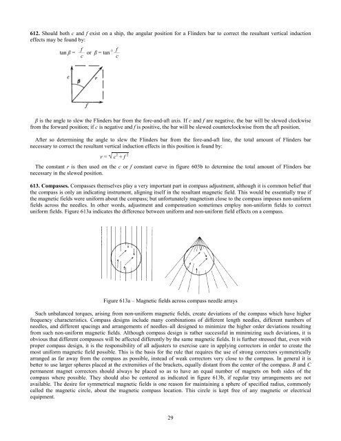
613. <strong>Compass</strong>es. <strong>Compass</strong>es themselves play a very important part in compass adjustment, although it is common belief that<br />
the compass is only an indicating instrument, aligning itself in the resultant magnetic field. This would be essentially true if<br />
the magnetic fields were uniform about the compass; but unfortunately magnetism close to the compass imposes non-uniform<br />
fields across the needles. In other words, adjustment and compensation sometimes employ non-uniform fields to correct<br />
uniform fields. Figure 613a indicates the difference between uniform and non-uniform field effects on a compass.<br />
Figure 613a – <strong>Magnetic</strong> fields across compass needle arrays<br />
Such unbalanced torques, arising from non-uniform magnetic fields, create deviations <strong>of</strong> the compass which have higher<br />
frequency characteristics. <strong>Compass</strong> designs include many combinations <strong>of</strong> different length needles, different numbers <strong>of</strong><br />
needles, and different spacings and arrangements <strong>of</strong> needles–all designed to minimize the higher order deviations resulting<br />
from such non-uniform magnetic fields. Although compass design is rather successful in minimizing such deviations, it is<br />
obvious that different compasses will be affected differently by the same magnetic fields. It is further stressed that, even with<br />
proper compass design, it is the responsibility <strong>of</strong> all adjusters to exercise care in applying correctors in order to create the<br />
most uniform magnetic field possible. This is the basis for the rule that requires the use <strong>of</strong> strong correctors symmetrically<br />
arranged as far away from the compass as possible, instead <strong>of</strong> weak correctors very close to the compass. In general it is<br />
better to use larger spheres placed at the extremities <strong>of</strong> the brackets, equally distant from the center <strong>of</strong> the compass. B and C<br />
permanent magnet correctors should always be placed so as to have an equal number <strong>of</strong> magnets on both sides <strong>of</strong> the<br />
compass where possible. They should also be centered as indicated in figure 613b, if regular tray arrangements are not<br />
available. The desire for symmetrical magnetic fields is one reason for maintaining a sphere <strong>of</strong> specified radius, commonly<br />
called the magnetic circle, about the magnetic compass location. This circle is kept free <strong>of</strong> any magnetic or electrical<br />
equipment.<br />
29


