(Microsoft PowerPoint - BIW10_\256\374\263\370)
(Microsoft PowerPoint - BIW10_\256\374\263\370)
(Microsoft PowerPoint - BIW10_\256\374\263\370)

You also want an ePaper? Increase the reach of your titles
YUMPU automatically turns print PDFs into web optimized ePapers that Google loves.
∆<br />
Amplitude<br />
detector<br />
3*RF<br />
Σ<br />
LP<br />
Rocker I/O Interface<br />
Heartbeat Register<br />
Ethernet Interface<br />
(Hardware UDP Stack)<br />
Heartbeat Register<br />
Control and Status<br />
Registers<br />
Horizontal Feedback<br />
Vertical Feedback<br />
Bunch Current Monitor<br />
RF<br />
Injection<br />
Trigger<br />
User<br />
trigger<br />
180<br />
0<br />
180<br />
0<br />
Slow Setting<br />
Buffer<br />
EPICS OPI<br />
&<br />
realtime and offline analysis<br />
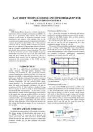
<strong>BIW10</strong>, TUPSM101, May 2-6, 2010<br />
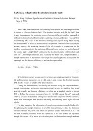
Design Status of the Diagnostic System for the TPS<br />
K. T. Hsu, K. H. Hu, , C. H. Kuo, P.C. Chiu, Jenny Chen, C. Y. Wu, S.Y. Hsu<br />
NSRRC, Hsinchu 30076, Taiwan<br />
Abstract<br />
Taiwan Photon Source (TPS) is a 3 GeV synchrotron light source which is being in construction at NSRRC. Designs of various<br />
diagnostics are undergoing and will deploy in the future to satisfy stringent requirements of TPS for commissioning, top-up injection,<br />
and operation. These designs which include beam intensity observation, trajectory and beam positions measurement, destructive<br />
profile measurement, synchrotron radiation monitors, beam loss monitors, orbit and bunch-by-bunch feedbacks, filling pattern and<br />
etc. are in final design phase. Details of current status and implementation of the planned beam instrumentation system for the TPS<br />
will be summarized in this report.<br />
Monitor<br />
YAG:Ce screen<br />
WCM<br />
FCT<br />
ICT<br />
Monitor<br />
FCT<br />
Monitor<br />
NPCT<br />
FCT<br />
Civil construction was started from February 2010.<br />
The building will be finished in 2012.<br />
Scheduled commissioning start in late 2013.<br />
View form this direction<br />
TLS<br />
(existed 1.5 GeV light source)<br />
YAG:Ce/OTR screen<br />
Linac diagnostics<br />
Quantity<br />
5<br />
1<br />
2<br />
1<br />
Beam parameters<br />
Position & Profile<br />
Intensity distribution<br />
Intensity distribution<br />
Charge at exit of the linac<br />
LTB diagnostics instruments<br />
Booster synchrotron diagnostics instruments<br />
BPM (4 button pick-ups)<br />
Set of striplines and amplifiers<br />
YAG:Ce screen (fluorescent<br />
screen)<br />
Synchrotron light monitor,<br />
profile and streak camera<br />
(visible light)<br />
Bunch cleaning system<br />
1<br />
1<br />
60<br />
2<br />
6<br />
2<br />
1<br />
6<br />
2<br />
Fill pattern<br />
-<br />
TPS<br />
TPS<br />
7 m straight center<br />
Dipole (1 o source point)<br />
Introduction<br />
The electron beam sizes and divergence<br />
σx’<br />
σy’<br />
Source point<br />
σx<br />
σy<br />
(μrad (μrad<br />
(μm) (μm)<br />
)<br />
)<br />
12 m straight center 165.10 12.49 9.85 1.63<br />
120.81<br />
39.73<br />
17.26<br />
76.11<br />
15.81<br />
Linac and Transport Line Diagnostics<br />
Quantity Beam parameters<br />
Quantity Beam parameters<br />
Position, profile(1 at diagnostic branch). OTR screen<br />
will be adopted for the site of high precision profile<br />
measurement to avoid saturation of YAG:Ce screen.<br />
Beam intensity<br />
5.11<br />
3.14<br />
1.11<br />
Circumference (m)<br />
Energy (GeV)<br />
Natural emittance (nm-rad)<br />
Revolution period (ns)<br />
Revolution frequency (kHz)<br />
Radiofrequency (MHz)<br />
Harmonic number<br />
SR loss/turn, dipole (MeV)<br />
Natural chromaticity ξx /ξy<br />
Dipole bending radius ρ(m)<br />
Repetition rate (Hz)<br />
Major parameters of the TPS booster<br />
synchrotron and the storage ring<br />
Booster Synchrotron<br />
150 MeV – 3 GeV<br />
10.32 @ 3 GeV<br />
603.865<br />
499.654<br />
0.586 @ 3 GeV<br />
Betatron tune νx /νy<br />
14.369/9.405 26.18 /13.28<br />
Synchrotron tune ns<br />
-<br />
0.00611<br />
Momentum compaction (α1 , α2 ) -<br />
2.4×10 -4 , 2.1×10 -3<br />
Natural energy spread<br />
9.553×10 -4<br />
8.86×10 -4<br />
Damping partition J x /J y /J s 1.82/1.00/1.18 0.9977/1.0/ 2.0023<br />
Damping time τx /τy/τs (ms) 9.34/ 16.96 / 14.32 12.20/ 12.17 / 6.08<br />
-16.86/-13.29<br />
17.1887<br />
TPS 150 MeV linac has been contract to RI Research Instruments GmbH.<br />
The schedule for delivery and commissioning is in early 2011 at test site.<br />
The linac will move to the TPS building in late 2012 after TPS building available.<br />
All diagnostics of the linac system is provided by the vendor.<br />
YAG:Ce screen monitors for beam position and profile observation.<br />
The fast current transformers (FCT) for monitor the distribution of charge.<br />
The integrating current transformer (ICT) for monitoring total bunch train charge.<br />
496.8<br />
1656<br />
828<br />
BTS diagnostics instruments<br />
3<br />
Storage Ring<br />
ICT<br />
1 Beam charge<br />
ICT<br />
2 Beam charge, installed at upstream<br />
BPM and single pass electronics 7 Beam position<br />
and downstream of the BTS<br />
Energy define slit<br />
1 1 pair of horizontal jar<br />
BPM and single pass electronics 6 Beam position, relative intensity<br />
The YAG:Ce fluorescence screens will provide information of beam position and profile.<br />
The OTR screens are also considered to be used for high precision of beam emittance and energy spread measurement<br />
The ICT will provide information of beam charge pass LTB and BTS and hence the beam losses during the injection cycle.<br />
The beam trajectory will be monitored with BPM equipped with Libera Brilliance Single-Pass, its functionality for single pass measurement.<br />
Averaged beam current<br />
Beam position<br />
Betatron tune, bunch<br />
cleaning system<br />
Beam profile and position<br />
at injection, extraction,<br />
and at every lattice cells<br />
Beam size (emittance),<br />
bunch length<br />
TLS<br />
Monitor<br />
YAG:Ce/OTR screen<br />
FCT<br />
Booster Ring Diagnostics<br />
Quanti<br />
ty<br />
3<br />
1<br />
Beam parameters<br />
Position, profile, booster<br />
extraction beam emittance<br />
Beam intensity<br />
518.4<br />
3.0<br />
1.6<br />
1729.2<br />
578.30<br />
499.654<br />
864<br />
0.85269<br />
-75 / -26<br />
8.40338<br />
Fluorescent screens will be installed at injection and extraction section and at the other<br />
lattice cells to facilitate booster commissioning, troubleshooting and psychology needing.<br />
Booster orbit will be monitored with 60 BPMs with turn-by-turn capability.<br />
The sum signal from the receivers can be used to monitor fast history of the beam current.<br />
Circulating current will be measured with NPCT, while bunch pattern will be monitored<br />
with FCT.<br />
For tune measurement, the electron beam will be excited with white noise using striplines.<br />
The beam response will be observed with a real-time spectrum analyzer connected to the<br />
dedicated BPM buttons with the front end.<br />
There will be an extra set of striplines for a bunch cleaning system and for users who need<br />
a specific filling pattern in the storage ring.<br />
Synchrotron radiation from a dipole will be used to observe the beam profile during<br />
energy ramping and emittance measurements.<br />
The capability to monitor bunch length with a streak-camera will be also provided.<br />
-<br />
Monitor<br />
NPCT<br />
Sum signal of BPM buttons<br />
BPM (4 button pick-ups)<br />
BPM (4 button pick-ups)<br />
Striplines<br />
Transverse kickers and<br />
amplifiers<br />
YAG:Ce screen<br />
(Fluorescent screen)<br />
PIN diode type beam loss<br />
monitors<br />
Scintillation loss monitor<br />
Scrapers<br />
Storage ring diagnostics instruments<br />
Synchrotron radiation diagnostics instruments<br />
Monitor<br />
X-ray pinhole camera<br />
Streak camera<br />
Time correlated single<br />
photon counting system<br />
(Visible light or X-ray)<br />
XBPM<br />
Visible light synchrotron<br />
light diagnostic station,<br />
Imaging and streak<br />
camera<br />
BPM<br />
TPS bunch-by-bunch feedback<br />
system<br />
Hybrid Network<br />
bunch<br />
Quantity<br />
2<br />
1<br />
1<br />
1 or 2 per<br />
beamline<br />
Possible cPCI DAC Configuration<br />
10 kHz Fast Setting Clock<br />
DO (LEMO connector, for timing measurement), Trigger out, Package received<br />
4<br />
Setting Buffer<br />
Fast SFP<br />
Setting #1 Port<br />
Fast<br />
Setting #4<br />
2 Rocket I/O ports<br />
2 GbE ports<br />
cPCI Bus<br />
Slow<br />
Setting<br />
Trigger<br />
10 kHz ~ 250 MHz<br />
FPGA<br />
Class A Power<br />
Amplifier x 4<br />
Σ ∆ x ∆ y<br />
Front-end<br />
FPGA<br />
x<br />
GbE<br />
Port<br />
One of an Implementation Option<br />
Distributed IFOB embedded in BPM modules<br />
BPM Electronics<br />
12bit ADC<br />
12bit ADC<br />
12bit ADC<br />
FPGA<br />
cPCI 32 ch, 20/18 bits<br />
DAC Module<br />
Slow Setting<br />
EPICS IOC<br />
Fast Setting<br />
16bit DAC<br />
16bit DAC<br />
16bit DAC<br />
Cell N Power Supply<br />
BPM Electronics<br />
Control Network<br />
1<br />
Beam parameters<br />
Emittance vertical and horizontal<br />
planes.<br />
Averaged profile, single turn profile,<br />
profile of the selected bunch.<br />
Bunch length.<br />
Cell N-1 Cell N+1<br />
XBPM satellite grouping<br />
BPM grouping and<br />
XBPM<br />
XBPM<br />
IFOB FPGA<br />
Electronics<br />
Electronics<br />
Timing Interface<br />
Control and Status Registers<br />
Cell N<br />
Readback<br />
Registers (6<br />
x 32)<br />
Quantity<br />
4~6 per<br />
cell<br />
2 sets per<br />
plane<br />
+<br />
1<br />
1<br />
168<br />
1<br />
1<br />
2<br />
1<br />
24<br />
XBPM<br />
Data Sniffer<br />
Filling pattern.<br />
Isolated bunch purity.<br />
Position and angle of ID radiations.<br />
Alternative beam size measurement<br />
(emittance), either imaging the<br />
vertical polarized synchrotron light<br />
or interferometer, bunch length.<br />
20/18 bit DACs<br />
Beam parameters<br />
Averaged beam current, beam lifetime<br />
Fill pattern, bunch current<br />
7 BPM/cell<br />
For bunch-by-bunch feedback pickups<br />
Betatron tune measurement<br />
Horizontal and vertical kicker for transverse<br />
feedback and bunch cleaning usage.<br />
Beam profile and position just after injection<br />
septum<br />
Beam loss pattern<br />
High counting rate type beam loss monitor<br />
1 set = 2 blades<br />
Storage Ring Diagnostics<br />
The storage ring diagnostics including averaged beam current, fill pattern,<br />
beam lifetime, closed orbit, working tunes, chromaticity, beam size, beam loss<br />
pattern, beam density distribution, emittance, bunch length, and etc.<br />
The NPCT provides a resolution of better than 1 µA/Hz 1/2 and has large<br />
dynamic range and bandwidth to make itself a versatile device for measuring<br />
lifetime and injection efficiency.<br />
The storage ring filling pattern observed from the sum signal of BPM buttons<br />
by wide bandwidth fast digitizer sampling at RF or a multiple of RF frequency<br />
will enable measurement of the bunch current to better than 0.5% accuracy.<br />
Libera Brilliance BPM was chosen as baseline design at the conceptual design<br />
phase.<br />
Updated BPM electronics platform equip with more advanced parts and<br />
enhanced functionality are in serious consideration and discussed with the<br />
possible vendor. The TPS will most likely adopt the new BPM platform.<br />
The photon diagnostics for the TPS storage ring will utilize visible and X-ray<br />
synchrotron radiation generated in a bending magnet.<br />
Visible light beamline will be built to measure various beam parameters by streak<br />
camera, CCD camera and interferometer.<br />
Synchroscan mode operate for the streak camera at 250 MHz is preferred. Integrating<br />
the streak camera system with EPICS is preferred.<br />
Two X-ray pinhole cameras imaging the electron beam from bending magnets is the<br />
baseline design for the emittance measurement and measure the electron beam size at all<br />
currents from < 1 mA to 400 mA.<br />
The X-ray photon BPMs (XBPM) will be installed at each beamline. The slow data for<br />
control system access and the fast data for feedback purpose.<br />
Prototype of Libera Photon has been testing intensively at the 1.5 GeV TLS.<br />
Measuring the filling pattern by using time correlated single photon counting (TCSPC)<br />
is also considered. And APD detector to detect scattered X-ray photon will provide signal<br />
input for the TCSPC system. More than six order of dynamic range are expected.<br />
Infrastructure for orbit measurement, control and feedback<br />
Slow orbit acquisition will perform by channel access to the BPM platform embedded EPICS IOC up to 10Hz<br />
rate.<br />
Fast orbit beam position will circulate around all BPM platform at 10 kHz rate by using FPGA grouping<br />
scheme (e.g. Diamond Communication Controller or Gigabit Ethernet Grouping) or a new design.<br />
The TPS will adopt special design high performance corrector power supply. The power supply will use analog<br />
regulator, adopt bias analogue PWM scheme to improve zero current crossover problem.<br />
Improves integrated noise level form DC to 1 kHz down to a few part per million of the output full scale<br />
corresponding to nano-radian level kick for slow corrector with maximum ±600 µrad kick.<br />
Control of each cell’s corrector will be through a special design 20 bits (or 18 bits) DAC module. This module<br />
will provide EPICS CA interface via cPCI backplane for configuration, and setting and status monitoring.<br />
The 10 KHz rate data stream fast setting ports might configure as Rocket I/O for orbit feedback application<br />
and Gigabit Ethernet for global feed-forward applications.<br />
Functionalities of this FPGA module will perform: one for BPM data grouping and the other for feedback<br />
engine. BPM data grouping provides a way to distribute all BPM and XBPM data around the TPS storage ring at<br />
all BPM platforms in 10 kHz rate.<br />
Orbit feedback computation will distribute to the FPGA modules installed at the BPM platform in each cell.<br />
Sniffer nodes will be setup to capture orbit information in 10 kHz rate for more than 10 sec and decimated data<br />
at lower rate for much longer record time for various applications and analysis.<br />
Bunch-by<br />
by-bunch bunch feedbacks and diagnostics<br />
Transverse coupled-bunch instability mainly caused by the resistive wall impedance and other sources will<br />
deteriorate beam quality. Two plane Bunch-by-bunch feedback system is planned to suppressed instabilities.<br />
Transverse feedback kickers are planned to adopt the SLS/ELETRA design and compatible with TPS vacuum<br />
vessel. Transverse signals pick-up will be used as an extra BPM and installed at location of high beta function.<br />
Beside feedback functionality, the feedback electronics and software also support bunch oscillation data capture<br />
for analysis to deduce rich beam information, tune measurement, bunch clearing, and beam excitation and etc.<br />
Features of the planned system include the latest high dynamic range ADC/DAC (12/16 bits), high performance<br />
FPGA, flexible signal processing chains, flexible filter design, bunch feedback, tune measurement, bunch cleaning,<br />
various beam excitation scheme, flexible connectivity, and seamless integrated with the control system.<br />
On-line control interface to operate feedback system and off-line analysis tools should be included.<br />
Testing of the Libera Bunch-by-Bunch and the iGp are on going at the 1.5 GeV Taiwan Light Source.<br />
Summary<br />
Beam diagnostics designs and implementation for the TPS are in proceed. Status is summarized in this report. The critical<br />
diagnostic systems, addressing beam stability and low emittance monitoring, are being investigated in the design phase. Major<br />
procurement are scheduled in 2011~2012. Optimizing the design, prototyping and working out on specifications are current efforts.<br />
System integration is planned in 2013. Delivering a best diagnostics system to satisfy stringent requirements of TPS is the goals.
Control<br />
30<br />
20<br />
10<br />
0<br />
-10<br />
-20<br />
20<br />
15<br />
10<br />
5<br />
0<br />
-5<br />
-10<br />
Time(sec)<br />
Time(sec)<br />
RCVCSPS21 current (mA)<br />
FOFB status<br />
BL10y<br />
r3bpm2y<br />
r3bpm3y<br />
20<br />
10<br />
0<br />
-10<br />
-100<br />
-150<br />
-200<br />
-250<br />
0<br />
-200<br />
-400<br />
EPU4.6 Phase change (mm) v.s. photon BPM Ib = 232.8672 mA;<br />
Time (sec)<br />
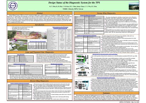
<strong>BIW10</strong>, TUPSM102, May 2-6, 2010<br />
Diagnostics Update of the Taiwan Light Source<br />
C. H. Kuo, P. C. Chiu, Y. S. Cheng, Y. K. Chen, K. H. Hu, C. Y. Wu, Demi Lee, S. Y. Hsu, Jenny Chen, Y. T. Chang, C. J. Wang, Y. R. Pan, K.T. Hsu<br />
NSRRC, Hsinchu 30076, Taiwan<br />
Diagnostics of the 1.5 GeV Taiwan Light Source (TLS) has been continuously upgraded since 1993. The BPM electronics of the TLS<br />
have been upgraded to the Libera Brilliance in August 2008 to improve performance and functionality. Orbit feedback system is also migrated<br />
into fast orbit feedback system to enhance orbit stability. Commercial photon BPM electronics was tested recently. New generation bunch-bybunch<br />
feedback processor was tested to improve beam stability. Post-mortem diagnostic tools were also set up to clarify reasons of beam trip.<br />
These upgrades are contributed to improve beam quality and machine availability a lots. These efforts will be addressed in this report.<br />
• The New BPM system has<br />
been commissioning in August<br />
2008. The long-term reliability<br />
is satisfied during observation<br />
for one and one-half years.<br />
• The resolution of 10 kHz data<br />
could be achieved 0.2 μm in<br />
rms.<br />
• Turn-by-turn data is provided<br />
by Libera Brilliance. Post<br />
mortem buffer with the length<br />
up to 256k could store beam<br />
turn by turn data before beam<br />
trip.<br />
• The commissioning of the new fast orbit feedback system<br />
has started from 2008.<br />
• The reflective memory is employed to shares fast orbit<br />
data without consuming extra CPU resource.<br />
• Libera Grouping is used to reduce Ethernet jitter.<br />
• Pseudo-random binary sequence (PRBS) excitation is<br />
employed to measure system response and latency and<br />
then choosing the proper correctors for FOFB.<br />
• The I/O latency time is around 500 msec. The computation<br />
latency is about 120 msec.<br />
• Singular value decomposition (SVD) is used to invert<br />
response matrix. Tikhonov regularization is also adopted.<br />
• The new FOFB is promoted to suppress noise of<br />
bandwidth to more than 50 Hz from old 6 Hz system after<br />
all components are upgraded. Increase loop bandwidth<br />
will be done after further study.<br />
Amplitude(µm/Hz 1/2 )<br />
RMS Integrated PSD(µm 2 /Hz)<br />
Hor. Position (µm)<br />
Ver. Position (µm)<br />
1.5<br />
1<br />
0.5<br />
0<br />
10 0<br />
10 -2<br />
10 -4<br />
5<br />
0<br />
Abstract<br />
New BPM System and Some Observation Delivery by the System<br />
-300<br />
-320<br />
-340<br />
-5<br />
0 10 20 30 40 50 60 70 80 90 100<br />
FOFB OFF<br />
FOFB ON<br />
5<br />
0<br />
-5<br />
0 10 20 30 40 50 60 70 80 90 100<br />
Time (sec)<br />
FOFB OFF<br />
FOFB ON<br />
Hor. pos ition (µ m )<br />
10 0 10 1<br />
10 0 10 1<br />
Frequency(Hz)<br />
The overall RMS orbit stability could be<br />
Hor. am plitude (µ m )<br />
submicron from DC to 50 Hz.<br />
• Some fast beam motion could be<br />
observed by the new BPM system.<br />
10<br />
5<br />
0 0.005 0.01 0.015 0.02 0.025 0.03<br />
Time (sec)<br />
0<br />
0 100 200 300 400 500<br />
Frequency (Hz)<br />
The beam orbit motions at 120 Hz<br />
caused by one problem corrector power<br />
supply.<br />
New Orbit Feedback System<br />
y Position σ (µm)<br />
y Position σ (µm)<br />
1<br />
0.8<br />
0.6<br />
0.4<br />
0.2<br />
WS/Unix<br />
200 Hz Rate<br />
Data<br />
Acquisition<br />
(200 sec 10 kHz<br />
Diagnostic) Rate Data<br />
Acquisition<br />
(8 sec Diagnostic)<br />
V<br />
MPMC<br />
E RM<br />
V<br />
H<br />
MPMC<br />
O<br />
E RM<br />
S<br />
DI<br />
T<br />
H /<br />
O DO<br />
S<br />
T<br />
GbE Interface External/Post-mortem<br />
Trigger<br />
Libera Group R1 GbE Grouping<br />
Libera Group R2<br />
Libera Group R3<br />
Libera Group R4<br />
10 kHz<br />
Rate<br />
Data<br />
Acquisition<br />
V<br />
MPMC<br />
E RM<br />
H<br />
O<br />
S<br />
T<br />
Libera Group R5<br />
Libera Group R6<br />
Super-period 1, 2, 3, 4, 5, 6 BPM<br />
0<br />
0 10 20 30 40 50 60<br />
1<br />
0.8<br />
0.6<br />
0.4<br />
0.2<br />
FOFB OFF<br />
FOFB ON<br />
0<br />
0 10 20 30 40 50 60<br />
BPM ID<br />
Standard deviation of all BPM<br />
SA reading (10 Hz rate) can be<br />
reduced to 0.2 μm during<br />
FOFB operation in the normal<br />
user mode for the vertical<br />
plane.<br />
R1 BP M 1 H O R. D isp . (µm )<br />
0<br />
-100<br />
-200<br />
-300<br />
-400<br />
-500<br />
0.02 0.04 0.06 0.08 0.1 0.12<br />
Time (sec)<br />
VME Host<br />
PowerPC 7448 @ 1 GHz<br />
PMC<br />
RM<br />
DI<br />
Horizontal<br />
Network<br />
16<br />
Bit<br />
D<br />
A<br />
C<br />
PC/Linux<br />
Reflective Memory<br />
Hub<br />
VME Host<br />
PowerPC 7448 @ 1 GHz<br />
PMC<br />
RM<br />
Vertical<br />
Control<br />
Consoles<br />
DI<br />
16<br />
Bit<br />
D<br />
A<br />
C<br />
Correction Magnet Power Supply<br />
V<br />
M<br />
E<br />
H<br />
O<br />
S<br />
T<br />
16<br />
Bit<br />
D<br />
A<br />
C<br />
PC/Linux<br />
16<br />
Bit<br />
D<br />
A<br />
C<br />
V<br />
MPMC<br />
E RM<br />
H<br />
O<br />
S<br />
T<br />
Plane<br />
Plane<br />
Inhibit Control Inhibit Control Corrector DC Control<br />
GbE Interface<br />
Fast Orbit Feedback setting (÷5 reduced VME<br />
GbE<br />
range)<br />
Grouping<br />
PS Control<br />
Libera Phton<br />
Analogue Sum<br />
Libera Phton<br />
250Injection<br />
every 60 sec<br />
Vertical Position (µm)<br />
200<br />
150<br />
100<br />
50<br />
0<br />
Before<br />
After<br />
Hor. injection amplitude (µm)<br />
Ver. injection amplitude(µm)<br />
1000<br />
500<br />
0<br />
-500<br />
-1000<br />
0 10 20 30 40 50 60<br />
200<br />
100<br />
0<br />
-100<br />
-200<br />
0 10 20 30 40 50 60<br />
BPM index<br />
The orbit distortion caused by septum<br />
leakage before and after chamber<br />
shielding. The excursion is improved to<br />
reduce around one half after chamber<br />
shielding.<br />
The infrastructure of the new orbit feedback system<br />
VME<br />
RM<br />
ILC12<br />
16<br />
Bit<br />
A<br />
D<br />
C<br />
16<br />
Bit<br />
A<br />
D<br />
C<br />
Vertical Position vs. Time; Ib = 302.03 mA; 07-Apr-2009 04:08:03<br />
Future Option<br />
Photon BPM<br />
Data<br />
Acquisition<br />
XBPMs<br />
EPU5.6 Phase Change (1 mm/sec)<br />
10 kHz Rate Data<br />
Acquisition<br />
r1bpm0y<br />
r1bpm1y<br />
r1bpm2y<br />
r1bpm3y<br />
r1bpm4y<br />
r1bpm5y<br />
r1bpm6y<br />
r1bpm7y<br />
r1bpm8y<br />
r1bpm9y<br />
r2bpm0y<br />
r2bpm1y<br />
r2bpm2y<br />
r2bpm3y<br />
r2bpm4y<br />
r2bpm5y<br />
r2bpm6y<br />
r2bpm7y<br />
r2bpm8y<br />
r2bpm9y<br />
r3bpm0y<br />
r3bpm1y<br />
r3bpm2y<br />
r3bpm3y<br />
r3bpm4y<br />
r3bpm4ay<br />
r3bpm5ay<br />
r3bpm5y<br />
r3bpm6y<br />
r3bpm7y<br />
r3bpm8y<br />
r4bpm0y<br />
r4bpm1y<br />
r4bpm2y<br />
r4bpm3y<br />
r4bpm4y<br />
r4bpm5y<br />
r4bpm6y<br />
r4bpm7y<br />
r4bpm8y<br />
r4bpm9y<br />
r5bpm0y<br />
r5bpm1y<br />
r5bpm2y<br />
r5bpm3y<br />
r5bpm4y<br />
r5bpm5y<br />
r5bpm6y<br />
r5bpm7y<br />
r5bpm8y<br />
r5bpm9y<br />
r6bpm0y<br />
r6bpm1y<br />
r6bpm2y<br />
r6bpm3y<br />
r6bpm4y<br />
r6bpm5y<br />
r6bpm6y<br />
r6bpm7y<br />
0 50 100 150 200 250 300 350<br />
Time (sec)<br />
Feedback ON Feedback OFF Feedback ON<br />
Effect of the FOFB to suppress orbit excursion<br />
due to phase change of EPU5.6<br />
Before<br />
After<br />
Before<br />
After<br />
• There are several kinds of<br />
photon BPMs with different<br />
electronics and data acquisition<br />
installed at beamline front-ends<br />
at the TLS. To provide a better<br />
integration and efficient usage<br />
of the photon BPMs, integrated<br />
solution is in study. Evaluate of<br />
the Libera Photon is on going.<br />
• Excellent results was achieved.<br />
Seamless integration with<br />
control system are foreseeable.<br />
Feedback Test<br />
Bunch Cleaning Test<br />
• iGp has integrated functionality<br />
for bunch cleaning.<br />
• Apply excitation at the vertical<br />
betatron tune.<br />
• The right figures show two<br />
cleaned out bunches patterns.<br />
• Killed all bunches except for one<br />
bunch, used for timing<br />
optimization.<br />
V e rt ic a l p o s itio n (µ m )<br />
30<br />
25<br />
20<br />
15<br />
10<br />
5<br />
0<br />
-5<br />
0.62 0.64 0.66 0.68 0.7 0.72 0.74 0.76 0.78 0.8 0.82<br />
Time (sec)<br />
Libera Photon Test<br />
BL10 Y<br />
Injection transient observed<br />
by the photon BPM (10 kHz<br />
rate data).<br />
Current (mA)<br />
Vertical position (µm)<br />
-30<br />
0 10 20 30 40 50 60<br />
FOFB OFF<br />
FOFB ON<br />
-15<br />
0 10 20 30 40 50 60<br />
iGp Bunch-by<br />
by-Bunch Signal Processor Commissioning<br />
• Based on existed bunch-by-bunch front-end, back-end, and<br />
power amplifiers.<br />
• Three planes was tested.<br />
• Longitudinal feedback test – Beam stabilized in 20 minutes.<br />
• Horizontal and vertical planes take a coupled of hours to make<br />
the system work.<br />
• 16-tap FIR filter.<br />
• One loop to stabilized instabilities in horizontal and vertical<br />
plane was also performed by using two peaks filter and got<br />
success results.<br />
• Matlab filter generator allows independent control of gain and<br />
phase for X and Y.<br />
• Lower X gain is intentional - to balance the two loops.<br />
• To identify the reasons of trips at TLS,<br />
various diagnostics tools are employed.<br />
• An earthquake detector has been<br />
installed to reveal the consequence of the<br />
trip caused by earthquake.<br />
• The right figure shows that an<br />
earthquake occurred at high sea of<br />
eastern Taiwan. The P wave arrive<br />
NSRRC site 42 seconds later. The S<br />
wave lag about 30 seconds after P wave.<br />
• The SRF system trip happened 20<br />
second after S wave arrived. The trip<br />
was caused by the vibration of Nb cavity<br />
which resulted in deformation of the<br />
cavity and consequently provoked<br />
resonance frequency shift.<br />
Cleaning is in proceed<br />
Post-mortem Diagnostics<br />
Beamline #10 photon BPM 10 Hz<br />
reading signal related to the<br />
electron BPM when driving<br />
corrector with/without FOFB.<br />
Grow/Damp Test<br />
-20<br />
0 50 100 150 200 250<br />
FOFB OFF FOFB ON<br />
• Grow/damp transient at 200 mA is measured.<br />
• Damping rate is twice as fast as the growth rate.<br />
• Damping rate is twice as fast as the growth rate at least for<br />
all three planes.<br />
Horizontal plane<br />
Most of the bunches killed<br />
Sequence of the earthquake and beam trip<br />
Phase change (mm)<br />
BL10 ver. pos. (µm)<br />
BL15 ver. pos. (µm)<br />
-300<br />
0 50 100 150 200 250<br />
-600<br />
0 50 100 150 200 250<br />
Photon beam displacement<br />
when the EPU5.6 phase<br />
changed with/without FOFB.<br />
Beam excursion could<br />
almost be suppressed.<br />
Vertical plane<br />
Only the selected bunch survive<br />
Summary<br />
Longitudinal plane<br />
• Diagnostics of the TLS has been<br />
continuously upgraded using<br />
available resources to improve<br />
performance and avoid obsolete.<br />
• New BPM system and fast orbit<br />
feedback system are commissioning.<br />
Performance tests are presented.<br />
• Photon BPM are testing.<br />
• Testing of the iGp and Libera<br />
Bunch- by-Bunch are ongoing.<br />
• Other diagnostic tools will be<br />
continuously added and built up to<br />
enhance system’s reliability and<br />
availability.