fast orbit feedback scheme and implementation for taiwan photon ...
fast orbit feedback scheme and implementation for taiwan photon ...
fast orbit feedback scheme and implementation for taiwan photon ...

Create successful ePaper yourself
Turn your PDF publications into a flip-book with our unique Google optimized e-Paper software.
FAST ORBIT FEEDBACK SCHEME AND IMPLEMENTATION FOR<br />
TAIWAN PHOTON SOURCE<br />
P. C. Chiu, C. H. Kuo, K. H. Hu, C. Y. Wu, K. T. Hsu<br />
NSRRC, Hsinchu 30076, Taiwan<br />
Abstract<br />
TPS (Taiwan Photon Source) is a 3 GeV synchrotron<br />
light source which is being in construction at NSRRC. As<br />
most of 3 rd generation light sources, the <strong>fast</strong> <strong>orbit</strong><br />
<strong>feedback</strong> system would be adopted to eliminate various<br />
disturbances <strong>and</strong> improve <strong>orbit</strong> stability. Due to the<br />
vacuum chamber material made of aluminium with higher<br />
conductivity <strong>and</strong> lower b<strong>and</strong>width, both of slow <strong>and</strong> <strong>fast</strong><br />
correctors will be used <strong>for</strong> FOFB correction. In general,<br />
there are two <strong>scheme</strong>s to operate these hybrid correctors.<br />
One is to transfer correction from <strong>fast</strong> to slow correctors<br />
periodically <strong>and</strong> avoid <strong>fast</strong> corrector saturation. The other<br />
is the <strong>fast</strong> correctors operated only at higher frequency<br />
domain <strong>and</strong> slow ones take care of DC part. TPS would<br />
adopt the first <strong>scheme</strong> but the second one still as a<br />
substitute. Both <strong>scheme</strong>s will be supported. This report<br />
summarizes the infrastructure of the FOFB <strong>and</strong> the<br />
simulation is also presented.<br />
INTRODUCTION<br />
The TPS is a state-of-the-art synchrotron radiation<br />
facility featuring ultra-high <strong>photon</strong> brightness with<br />
extremely low emittance [1]. This synchrotron machine<br />
requires beam position stability less than 1/10 beam size<br />
there<strong>for</strong>e the FOFB is also required to stabilize <strong>orbit</strong> <strong>and</strong><br />
achieve one hundred or even tens of nanometer resolution.<br />
The FOFB is mainly implemented by three parts: BPM,<br />
<strong>feedback</strong> computation unit <strong>and</strong> corrector power supply<br />
control interface. The TPS BPM electrical system will<br />
adopt the latest I-tech product: Brilliance+ [2] <strong>and</strong> its<br />
acceptance test <strong>for</strong> all units had been completed during<br />
June to August of 2012 to verify to meet fundamental<br />
specifications <strong>and</strong> functionalities. It also offers a large<br />
playground <strong>for</strong> custom- written applications with Virtex 6<br />
in the gigabit data exchange module (GDX) to be used as<br />
<strong>orbit</strong> <strong>feedback</strong> computation. The corrector power-supply<br />
controller (CPSC) is designed <strong>for</strong> FOFB corrector control<br />
interface. This module is embedded with Intel XScale<br />
IOP <strong>and</strong> Xilinx Spartan-6 FPGA which will interface the<br />
<strong>fast</strong> setting from <strong>feedback</strong> engines. It was contracted to<br />
D-TACQ [3].<br />
THE BPM AND GDX INTERFACE<br />
The BPM electronics consists of four kinds of modules:<br />
The timing module <strong>for</strong> clock locking <strong>and</strong> trigger; up to<br />
four BPM modules <strong>for</strong> receiving button pick-ups <strong>and</strong><br />
signal processing, the inter-connection board (ICB)<br />
module <strong>for</strong> SW <strong>and</strong> HW interface; the GDX (Gigabit data<br />
exchange) module <strong>for</strong> FA data grouping <strong>and</strong> FOFB<br />
computation.<br />
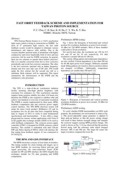
Preliminary BPM testing<br />
Fig. 1 shows the histogram of horizontal <strong>and</strong> vertical<br />
position SA resolution distibution at power level around -<br />
10 dBm <strong>for</strong> 228 BPM modules. Most of these modules<br />
could achieve 20 nm resolution.<br />
For turn-by-turn data, the resolutions are 150 <strong>for</strong> 0.5<br />
mA <strong>and</strong> 10 um <strong>for</strong> 10 mA respectively. FA data<br />
resolution is around 100 nm <strong>for</strong> 100 mA.<br />
The current, filling pattern <strong>and</strong> temperature dependency<br />
are also verified. Current dependency is less than 200 nm<br />
<strong>for</strong> 40 dB input power level changes. Different camshaft<br />
mode filling patterns are tested to observe position almost<br />
not changed (
control <strong>and</strong> 0.05 nrad <strong>for</strong> <strong>fast</strong> ones. Noise level is around -<br />
120 dB where it would contribute 200 nm RMS <strong>orbit</strong><br />
disturbances from total 168 slow correctors <strong>and</strong> 10 nm <strong>for</strong><br />
96 <strong>fast</strong> correctors. Compared to slow correctors, <strong>orbit</strong><br />
disturbance cause by <strong>fast</strong> correctors could be ignored.<br />
Furthermore, the <strong>fast</strong> corrector response is corresponded<br />
to the 1.3 kHz b<strong>and</strong>width. The test results are shown as<br />
Fig. 5.<br />
-999.05<br />
-999.06<br />
Figure 3: FOFB GDX closed loop test. The upper plot is<br />
position; the lower plot is relative power level change.<br />
CORRECTOR POWER SUPPLY<br />
CONTROL INTERFACE<br />
The corrector power supply module is a sophiscated<br />
switching power supply with analogue regulator [5]. It<br />
will be applied <strong>for</strong> slow correctors, <strong>fast</strong> correctors, skew<br />
quadrupoles <strong>and</strong> etc. Each power suply sub-rack<br />
accomodates up to eight power supply modules. The<br />
center slot is allocated to install a special designed<br />
EPICS IOC with <strong>feedback</strong> support.<br />
The corrector power-supply controller (CPSC)<br />
module is embedded with ARM processor <strong>and</strong> Xilinx<br />
Spartan-6 FPGA. It was contracted to D-TACQ. This<br />
module will be installed at center slot of the power<br />
supply sub-rack. The module embedded EPICS IOC <strong>and</strong><br />
FPGA supports slow access <strong>for</strong> the EPICS CA clients<br />
<strong>and</strong> <strong>fast</strong> settings from <strong>orbit</strong> <strong>feedback</strong> system or the<br />
feedfoward application such as skew compensation. The<br />
<strong>fast</strong> settings from <strong>feedback</strong> engines with rocket I/O or<br />
feed-<strong>for</strong>ward engines with Gigabit ethernet will be<br />
sumed together with slow settings in CPSC to regulator<br />
module of corrector. The functional block diagram of<br />
CPSC module is shown in Fig. 4.<br />
External<br />
Clock<br />
Input<br />
DO (LEMO connector, <strong>for</strong> timing measurement), Trigger out, Package received<br />
Fast<br />
Setting SFP Port<br />
Setting Buffers<br />
Ports (GbE, Rx<br />
Ethernet Interface<br />
UDP/IP),<br />
(Hardware UDP Stack)<br />
Tx<br />
Through<br />
Heartbeat Register<br />
Port<br />
Fast<br />
Rx<br />
Setting Port,<br />
AURORA<br />
Through Tx<br />
Port<br />
Heartbeat Register<br />
(AURORA)<br />
Trigger (3 Hz) Sequencer ~8 x 64 k x 32 bit<br />
Data Acquisition10 kHz clock Wave<strong>for</strong>m Memory<br />
Trigger input<br />
Slow Setting<br />
Slow Trigger<br />
Buffer<br />
(on dem<strong>and</strong>, may not necessary)<br />
Slow Access (~ 10 Hz)<br />
Gigabit<br />
Ethernet<br />
Internal 10 kHz Clock Generator<br />
Up to 10 kHz Fast Setting Clock)<br />
Control <strong>and</strong> Status Registers<br />
Single Board Computer<br />
(Linux, EPICS IOC)<br />
10 kHz rate<br />
wave<strong>for</strong>m<br />
10 Hz rate data<br />
Wave<strong>for</strong>m Memory<br />
Free running<br />
Or Pre/Post Trigger<br />
Slow Access<br />
(~ 10 Hz)<br />
Control <strong>and</strong><br />
Status Registers<br />
4 ways,<br />
8 ch adder<br />
+<br />
Individual<br />
Channel<br />
Enable/Disable<br />
24 ch, 16 bit ADC<br />
Status Registers<br />
8 bit DI<br />
Write Registers<br />
8 bit DO<br />
8 Ch, 20 bit DAC<br />
Precise<br />
digital<br />
temperature<br />
sensors<br />
96 pin<br />
DIN61412<br />
Connectors x 2<br />
8 ch, 24 bit ADC<br />
(10 kHz Sampling)<br />
+/- 15 V<br />
+ 5 V<br />
Figure 4: Functional block diagram of the corrector power<br />
supply controller module. Fast setting from <strong>orbit</strong> <strong>feedback</strong><br />
<strong>and</strong> slow setting from EPICS CA console.<br />
Preliminary corrector power supply testing<br />
The power supply achieves 20 bit per<strong>for</strong>mance where<br />
it is equivalent to 1 nrad resolution <strong>for</strong> slow corrector<br />
Current (mA)<br />
-999.07<br />
-999.08<br />
-999.09<br />
-999.1<br />
-999.11<br />
-999.12<br />
Volt<br />
Volt<br />
Amp<br />
75 80 85 90 95<br />
(a)<br />
10 -5 imonitor: shunt<br />
10 -6<br />
10 -7<br />
0 200 400 600 800 1000<br />
Volt<br />
10 -5 imonitor: dcct<br />
10 -6<br />
10 -7<br />
0 200 400 600 800 1000<br />
Frequency(Hz)<br />
1.2<br />
1<br />
0.8<br />
0.6<br />
0.4<br />
0.2<br />
0<br />
(b)<br />
Vertical Fast Step Response<br />
Model<br />
-0.2<br />
0 2 4 6 8 10 12 14 16<br />
Time (msec)<br />
(c)<br />
Figure 5: (a) 20 bit per<strong>for</strong>mance, each step is around 20<br />
uA. (b) Noise level is around 1uA (c) Step response of<br />
vertical corrector power supply.<br />
FAST ORBIT FEEDBACK WITH SLOW<br />
CORRECTOR COMPENSATION<br />
The lattice layout <strong>for</strong> one cell of TPS storage ring is as<br />
Fig. 6. There are 7 BPMs <strong>and</strong> 7 horizontal/vertical<br />
correctors are winding on the sextupoles in each cell to<br />
provide hundreds of micro-radian kick strength while<br />
their b<strong>and</strong>width could be limited much less than 100 Hz<br />
due to the TPS alumni vacuum chamber. There<strong>for</strong>e, extra<br />
four <strong>fast</strong> horizontal/vertical correctors are installed on the<br />
bellows which have <strong>fast</strong> response but smaller trim<br />
strength around 20~30 urad [6]. The <strong>fast</strong> corrector will be<br />
used <strong>for</strong> <strong>feedback</strong> correction to suppress various
disturbance <strong>for</strong>m DC to 300 Hz. Another process will<br />
have to check the <strong>fast</strong> corrector setting periodically <strong>and</strong><br />
transfer DC part setting to the nearby slow correctors<br />
when accumulating to avoid saturation. FOFB integration<br />
test will be possible in 2014.<br />
Figure 6: One cell of 24 double-bend cells <strong>for</strong> TPS lattice<br />
layout.<br />
Simulation result<br />
Static simulation <strong>for</strong> vertical FOFB is per<strong>for</strong>med as Fig.<br />
7. It is assumed the r<strong>and</strong>om noises including qaudrupole 1<br />
um displacement <strong>and</strong> slow corrector 100 nrad noise <strong>and</strong><br />
then acquires σ y from 200 simulation results. The amplify<br />
factor would cause average 40 um <strong>orbit</strong> displacement<br />
without FOFB while the <strong>orbit</strong> displacement could be<br />
suppressed less than 1 um when applying FOFB. See Fig.<br />
1, the upper plot selects all of 7 BPMs in one cell; the<br />
lower plot selects only 5 BPMs in one cell where it results<br />
in larger displacement in bending section while the<br />
straight line displacement still could achieve 300 nm<br />
stability.<br />
Displacement σ y<br />
(µm)<br />
Displacement σ y<br />
(µm)<br />
1<br />
0.5<br />
0<br />
0.5<br />
7 bpm <strong>for</strong> one cell<br />
0 10 20 30 40 50 60 70 80<br />
S - position (m)<br />
1<br />
0<br />
5 bpm <strong>for</strong> one cell<br />
0 10 20 30 40 50 60 70 80<br />
S - position (m)<br />
Figure 7: Static simulation <strong>for</strong> FOFB shown in 4 cells.<br />
Amplitude(dB)<br />
10<br />
5<br />
0<br />
-5<br />
-10<br />
-15<br />
-20<br />
-25<br />
Corrector+Vaccum Plant<br />
Model<br />
Noise suppression<br />
-30<br />
10 0 10 1 10 2 10 3<br />
Freq (Hz)<br />
Fig. 8. The noise amplification effect will occurs at 600<br />
Hz far away from major noise spectra.<br />
Fig. 9 shows the transaction when DC part of <strong>fast</strong><br />
corrector transfer to slow corrector. At 50 msec, a kick<br />
cause <strong>orbit</strong> excursion <strong>and</strong> soon FOFB suppress it in 10<br />
msec <strong>and</strong> it results in one corrector (<strong>fast</strong> VC011) has 60<br />
mA DC offset. At 100 msec, the nearby slow (slow<br />
VC011) take DC parts of the slow correctors <strong>and</strong> <strong>fast</strong><br />
corrector decreasing to zeros. The transaction between<br />
slow <strong>and</strong> <strong>fast</strong> will only cause <strong>orbit</strong> disturbance less than 1<br />
um <strong>and</strong> vanish in 10 msec.<br />
Currecnt (A)<br />
Ver. Position (um)<br />
2<br />
1<br />
0<br />
-1<br />
-2<br />
0<br />
-0.02<br />
-0.04<br />
-0.06<br />
y pos.<br />
20 40 60 80 100 120 140<br />
Slow VC011<br />
Fast VC011<br />
noise kick<br />
20 40 60 80 100 120 140<br />
Time (msec)<br />
Figure 9: Transaction simulation when the <strong>fast</strong> corrector<br />
DC setting is transfer red to the nearby slow corrector<br />
CONCLUSION<br />
BPM electronics <strong>and</strong> <strong>fast</strong> <strong>orbit</strong> <strong>feedback</strong> system<br />
combined with slow <strong>and</strong> <strong>fast</strong> correctors of the TPS are<br />
summarized. The BPM electronics completed acceptance<br />
test in 2012. CPSC will be delivered in 2013. Preliminary<br />
tests <strong>for</strong> done. Installation <strong>and</strong> system integration will be<br />
per<strong>for</strong>med in early 2014. Plat<strong>for</strong>m development is also on<br />
going to develop various software supports.<br />
REFERENCE<br />
1. TPS Design H<strong>and</strong>book, version 16, June 2009.<br />
2. http://www.i-tech.si.<br />
3. http://www.d-tacq.com.<br />
4. Pei-Chen Chiu, et al., “TPS BPM Per<strong>for</strong>mance<br />
Measurement <strong>and</strong> Statistics”, Proceeding of IBIC<br />
2012, Tsukuba, Japan.<br />
5. K. B. Liu, „ TPS Correct Magnet Power Converter“,<br />
Proceedings of IPAC’10, WEPD073, Kyoto, Japan.<br />
6. C. H. Kuo, et al., “BPM System <strong>and</strong> Orbit Feedback<br />
System <strong>for</strong> the Taiwan Photon Source”, Proceeding of<br />
ICALEPCS 2011.<br />
Figure 8: Simulation of noise sensitivity function of the<br />
FOFB system.<br />
The b<strong>and</strong>width of the FOFB to suppress noise is<br />
estimated around 300 Hz which is limited primarily by<br />
corrector <strong>and</strong> chamber. The simulation result is shown in