INDUSTRIAL LIFTING PRODUCTS - Lift Turn Move
INDUSTRIAL LIFTING PRODUCTS - Lift Turn Move
INDUSTRIAL LIFTING PRODUCTS - Lift Turn Move

Create successful ePaper yourself
Turn your PDF publications into a flip-book with our unique Google optimized e-Paper software.
Hoists / Track / Winches / Jacks / Pulleys / CLAMPS - ALL IN ONE PLACE<br />
<strong>Lift</strong>ing Equipment and Systems for Industrial and Entertainment Industries<br />
<strong>INDUSTRIAL</strong> <strong>LIFTING</strong> <strong>PRODUCTS</strong><br />
<strong>Lift</strong> <strong>Turn</strong> <strong>Move</strong> Ltd, Version 2, August 2012<br />
Specifications
<strong>Lift</strong> turn move ltd<br />
2<br />
Contact Details<br />
LTM - <strong>Lift</strong> <strong>Turn</strong> <strong>Move</strong> Ltd tel: +44 (0)151 649 0467<br />
Unit 2 Stadium Court fax: +44 (0)151 649 0099<br />
Wirral International Business Park Email: sales@<strong>Lift</strong><strong>Turn</strong><strong>Move</strong>.co.uk<br />
Plantation Road<br />
www.liftturnmove.co.uk<br />
Bromborough<br />
Wirral CH62 3QG<br />
Sales Contacts:<br />
mObile Direct dial email<br />
Robert Price 07939 592 025 0151 649 1052 RobertPrice@liftturnmove.co.uk<br />
Ric Nuttall 07989 355 007 0151 649 1050 RicNuttall@liftturnmove.co.uk<br />
Peter Ashford 07774 257 409 - PeterAshford@liftturnmove.co.uk<br />
Jenny Steenson - 0151 649 1054 JennySteenson@liftturnmove.co.uk<br />
Head of industrial products:<br />
James Porter 07852 928 798 0151 649 1051 JamesPorter@liftturnmove.co.uk<br />
TECHNICAL CONTACT: ACCOUNTS CONTACT:<br />
works@liftturnmove.co.uk<br />
accounts@liftturnmove.co.uk<br />
Opening Hours: Monday - Friday 9.00am - 5.00pm the office is often open outside these times.<br />
Deliveries: We use various methods of delivery and can deliver more or less whenever you need.<br />
To stay up to date with the latest events at LTM please follow us on Facebook, Twitter and LinkedIn<br />
liftturnmove<br />
@<strong>Lift</strong><strong>Turn</strong><strong>Move</strong><br />
@<strong>Lift</strong> <strong>Turn</strong> <strong>Move</strong> Ltd<br />
LTM – <strong>Lift</strong> <strong>Turn</strong> <strong>Move</strong> Ltd<br />
<strong>Lift</strong> <strong>Turn</strong> <strong>Move</strong> Ltd (LTM) is an independent company, wholly owned and operated by the people who run the business day to day. This ensures decisions and<br />
actions are made swiftly and customer service is our top priority.<br />
LTM was set up in September 2004, with the aim of being customer focused and an enjoyable but professional place to work. We have eight sales staff, eight<br />
works staff (including two apprentices) and two staff in administration roles. All sales, technical and workshop staff hold LEEA qualifications and LEEA Team<br />
Cards and have on-going product training. Our processes are audited and checked by LEEA (<strong>Lift</strong>ing Equipment Engineers Association), of which we are full<br />
members.<br />
Markets, Clients and Products<br />
LTM operates in markets in which <strong>Lift</strong>ing, Handling, Supporting, <strong>Turn</strong>ing or Moving Loads are required. We supply an extensive range of Equipment and Solutions<br />
for use within the Engineering, Logistics, Construction, Utilities and Energy Industries. We also supply the Professional Leisure, Entertainment and Theatrical<br />
Industries.<br />
Our main clients are lifting gear re-sellers, dealers, system integrators, project installers, stage engineering companies, entertainment production companies,<br />
original equipment manufacturers and equipment rental companies.<br />
We offer Equipment and Solutions including Electric Chain Hoists, Control and Motion Control Systems, Manual <strong>Lift</strong>ing & Handling Equipment, Winches, Davits,<br />
Light Crane Systems, Jacks and Sluice Gate Jacks.<br />
Distributor Sales Policy<br />
As a <strong>Lift</strong> <strong>Turn</strong> <strong>Move</strong> (LTM) distributor of branded hoists, winches, jacks and lifting equipment, you have an opportunity to add further income and profit to<br />
your company by dealing with one of the most respected suppliers. With over 200 man years of lifting equipment experience we focus on high specification<br />
applications that require safety provided by its quality equipment range.
<strong>Lift</strong> turn move ltd<br />
LTM offers brands with a reputation for value, performance and quality engineering.<br />
• GIS Electric hoists, Track and Vacuum systems - the number one choice and a brand with instant global recognition for chain hoist applications.<br />
• Haacon - German engineering quality in Winches and Jacks<br />
• Ableforge Manufacturing Inc. - a quality Hand Chain Block and Manual Handling Equipment range<br />
3<br />
From our facilities in Bromborough we support distributors with a total package of help, advice and assistance from sales and workshop staff, marketing,<br />
promotion and training materials, spare parts and full technical support. Our staff are friendly, helpful and part of a good team of colleagues working together.<br />
In today’s tough economic climate it makes sense to explore every avenue to boost turnover and profits, and if you are interested in becoming an LTM distributor<br />
we would be happy to visit you to discuss how joining us could help you achieve your commercial ambitions.<br />
Websites, Information, and Product Documentation<br />
For further information about LTM and its products, people and services, please visit; www.liftturnmove.co.uk, and follow us on Facebook, Twitter & LinkedIn.<br />
All LTM products are supplied with comprehensive operating instructions. Also included is an EC Declaration of Conformity which confirms the certified status<br />
of the product.<br />
Additional operating manuals, spare part lists, wiring diagrams, maintenance instructions and technical drawings etc. are available on request or from our<br />
websites.<br />
Support with your marketing & promotional efforts<br />
As a commitment to our distributors, we have developed product and industry specific brochures, product charts, safety posters, flyers, interactive CD’s and<br />
websites.<br />
Please contact your sales contact for all literature, posters, images, videos, photographs, website advice and information, fonts or logos.<br />
We are happy to release the copyright of all our images for use on distributor’s websites or in your own brochures providing written consent is obtained from<br />
<strong>Lift</strong> <strong>Turn</strong> <strong>Move</strong> Ltd.<br />
Product Training & familiarization<br />
LTM continues to offer high quality equipment familiarisation and product training courses for our clients. Please consult either our web site or your normal<br />
contact at LTM if you would like to attend any of the courses that we run.<br />
Having moved premises recently we are constructing a new lifting equipment training centre in Bromborough. The school will provide a variety of courses to<br />
help employers and users operate, maintain and service GIS hoists, winches and other equipment that we offer.<br />
Experienced LTM training staff with experience of use and maintenance of lifting equipment ensure practical and thorough training in line with current legislation.<br />
As well as providing training for users, the centre will be available for companies who wish to run their own specific safety and lifting operation courses.<br />
Examples of training courses currently available include:<br />
• GIS training schools- Repair & Maintenance of electric chain hoists.<br />
• Able Forge training Schools- Repair and maintenance of manual chain hoists.<br />
• LoadGuard® Entertainment Hoist Training Schools.<br />
• Repair and Maintenance of Winches and Jacks<br />
Workshop Services<br />
We can offer repairs, routine maintenance and Thorough Inspections on all our products at our UK workshop. However our products are also available through<br />
the main stockists of our equipment throughout the UK and overseas who also undertake inspection, repairs, installation and servicing.
<strong>Lift</strong> turn move ltd<br />
4<br />
Policies…. We would like to draw your attention to some of our policies<br />
Goods Return Policy<br />
Either when incorrect goods are ordered by the distributor or the user or when goods are dispatched but later cancelled or are unwanted by the distributor or<br />
end user the following policy applies:<br />
On either of the above occasions, unless otherwise confirmed to the contrary in writing we will levy a standard handling charge. This handling charge is to cover<br />
administration costs, inspection and restocking of the returned goods.<br />
The handling charge on standard products is 15% of the net value minus any carriage costs. (Standard products are products in this brochure which are not<br />
manufactured to order).<br />
For non- standard products the handling charges is 25%<br />
Items that have been manufactured to a customer’s special requirement CANNOT be returned for credit.<br />
Returns Authorisation Number Request<br />
Before any goods are returned the distributor must contact a member of the sales team to gain a Returns Authorisation Number and form (RAN)<br />
Goods that arrive at without a RAN number and form will not be accepted and may be refused by our goods inward department, delaying any credits due.<br />
Upon the accepted return of goods, each item will be inspected and if on inspection it is noted that refurbishment is required before it can be returned into<br />
general stock the company will charge for this refurbishment. This work will be done at our standard repair charge rate and we will inform you of the faults or<br />
damage noted and the work required to reinstate the item to a saleable condition.<br />
All returned goods are to be returned by the distributor at their cost with a copy of the RAN number clearly marked on the goods and the completed form.<br />
Quality Policy Statement<br />
<strong>Lift</strong> <strong>Turn</strong> <strong>Move</strong> Ltd provides a range of products and standard of service that we hope fully meets your needs. We inspect every item and load test every hoist<br />
we sell. We are working towards ISO 9001, the internationally recognised standard of quality assurance.<br />
LTM are full members of LEEA- the <strong>Lift</strong>ing Equipment Engineers Association, our processes are audited yearly and checked by LEEA Technical Officers.<br />
Warranty Claims<br />
All equipment complies with the high standards of quality established in respect of materials and workmanship and as the sole and exclusive remedy in<br />
discharge of this warranty the company undertakes to replace free of charge within 12 months from date of dispatch from its works any components which are<br />
provided to the satisfaction of the company (whose decision shall be final and binding) to be defective in materials and workmanship.<br />
This is provided notice in writing to the company is given within 10 days of the defect occurring and provided the component which is the subject of the<br />
complaint is returned pre-paid to our works at Bromborough.<br />
In the case of defective components or parts not of the company’s manufacture the company’s liability shall be limited so such adjustment or allowance as the<br />
manufacturer shall offer.<br />
Note- <strong>Lift</strong> <strong>Turn</strong> <strong>Move</strong> Ltd will not accept responsibility for such work done or expense incurred by the buyer in connection with any repair or replacement unless<br />
the company’s prior written authorisation has been obtained.<br />
This warranty is in lieu and excludes all other conditions and warranties whatsoever whether expressed or implied and whether under common law, statue<br />
law otherwise and apart from aforesaid the company hereby expressly excludes all liability for any loss or damage whatsoever arising and howsoever caused.<br />
The buyer warrants that it will pass on, to all third parties to whom it may supply the goods, all information as to the use and safe handling of the goods, as<br />
may have been passed onto the buyer by the company.<br />
Why Use LTM<br />
We pride ourselves on fast response and delivery. The attitude of our staff makes a difference; we would not be where we are today, or where we are going to<br />
be in the future without them.<br />
We hold an extensive range of equipment including spare parts at our premises in the UK but without the understanding of the needs of demanding and rapidly<br />
moving industries by our staff we would not have the support in place that you need.<br />
All our staff hold qualifications relating to the products and services we supply; this is something we are very proud of.<br />
When to deal with LTM, you get experience, problem solving and most of all flexibility – free of charge.
Contents<br />
2-5 Introduction to <strong>Lift</strong> <strong>Turn</strong> <strong>Move</strong> Ltd & Contacts, Policies & Contents<br />
6-30 GIS Products; Electric Hoists, KB Track and Vacuum <strong>Lift</strong>ing Equipment<br />
5<br />
31-51 Ableforge Manufacturing Inc. Equipment (Manual Hoisting & Handling Equipment)<br />
52-56 Silverline Manual <strong>Lift</strong>ing Equipment & Beam Clamps<br />
57-58 Winch Information<br />
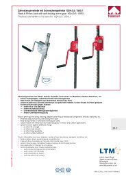
59-64 Winches - Spur Gear; Wall Mounted<br />
65 Winches - Spur Gear; Wall/Base Mounted<br />
66-71 Winches - Spur Gear; Base/Column Mounted<br />
72-75 Winches - Worm Gear; Wall mounted<br />
76-83 Winches - Harsh Environment & Special Application Winches<br />
84-87 Pulleys and Sheaves<br />
88-89 Gearbox & Braked Safety Cranks<br />
90-91 Load & Fall Arrestors<br />
92-95 Electric Winches<br />
96-100 Rack and Pinion Jacks & Steel Jacks<br />
101-103 Spindle Supports - Jacking Legs<br />
104 Cable Drum Jacks - Screw type<br />
105-113 Sluice Gate Drives & Water Industry Products<br />
114-117 Spare parts list - Silverline/Rexline Hoists<br />
118-145 Spare parts list - GIS GCH Electric Chain Hoists (V1 & V2)<br />
146-149 LoadGuard - Overview of Entertainment <strong>Lift</strong>ing Equipment & Systems<br />
150-155 Technical information (IP & FEM data), conversion table
Overview of GIS Products<br />
6<br />
<strong>Lift</strong>ing technology<br />
GIS GCH electric chain hoists (125 to 5,000 kg)<br />
• Hard working, low wear, reliable, easy to maintain<br />
• Application: stationary, movable on I-beams or combined with GIS crane system<br />
Crane technology<br />
GISKB crane system (up to 1,250 kg) - Steel or aluminium<br />
• Modular concept<br />
• Single and double bridge suspended crane for all-round goods transportation<br />
• Monorail with bends and switches for linebound transportation<br />
• Lightweight design<br />
GIS travelling cranes (up to 5,000 kg)<br />
• Designed to customer specifications<br />
• Conventional design<br />
• Especially suitable for larger spans<br />
GIS slewing pillar and wall cranes (up to 1,000 kg)<br />
• For use when ceilings have insufficient load-bearing capacity<br />
• An ideal addition to your suspended crane<br />
• Quick to plan, simple, easy to handle<br />
Vacuum lifting technology<br />
Gentle lifting with GIS vacuum equipment (up to 500 kg)<br />
• For all types of surfaces and a huge variety of products<br />
• Can be combined with electric chain hoists/wire rope hoists<br />
Benefits to you:<br />
• Quality products<br />
• Tested and proven thousands of times over<br />
• Simple design and installation<br />
• Extendable at any time
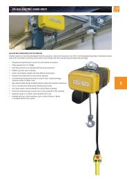
GIS gch Electric chain hoists<br />
7<br />
GIS GCH Electric Chain Hoists (125 to 5000 kg)<br />
A further evolution in chain hoist development from GIS, specialists in chain hoist manufacture since 1963. The GIS manufacturing facility in Switzerland contains<br />
some of the most modern machining centres and the hoist embodies the latest manufacturing techniques and technology.<br />
• Designed and manufactured to work in the most extreme of conditions<br />
• <strong>Lift</strong>ing capacity from 125–5000kg<br />
• Hoist body and end covers manufactured from die cast aluminium<br />
• Reliable, low wear, easy to maintain<br />
• Single or dual speeds available with many different speed options<br />
• Permanent hoist lubrication for wear resistant operation<br />
• Cast aluminium housing and end covers using the latest casting technology,<br />
maximum solidity (not plastic)<br />
• New advanced brake design providing maximum safety with minimum maintenance<br />
• Five or six pocket chain wheel giving extremely quiet running<br />
• 42V control system, electrical geared limit switches fitted as standard<br />
• Fitted with mechanical stops to prevent over travel as required in FEM standards<br />
• Ergonomic design 2 or 4 button control pendant with E stop<br />
• Available with Eye or Hook suspension, push or electric trolley on I-Beams<br />
or combined with GIS crane system
GIS GCH Electric Chain Hoist - Features<br />
8<br />
Brake<br />
• Maximum safety (construction<br />
with brake after slipping clutch)<br />
• New advanced brake design<br />
• Maintenance free<br />
Chain wheel<br />
• Made of hardened steel<br />
• 5 & 6 chain pockets, hence quiet running<br />
and improved running properties<br />
• With double bearing construction<br />
Geared limit switch (standard)<br />
• Simple adjustment<br />
• Exact positioning<br />
• <strong>Lift</strong>ing heights up to 220 m<br />
• Accuracy for repetition assured<br />
Transmission<br />
• Helical-toothed first and second gear<br />
step for quiet running<br />
• Permanent lubrication for wear<br />
resistant operation<br />
Contactor control system<br />
• Simple technology (no electronics<br />
susceptible to interference)<br />
• Reliable technique<br />
• Emergency stop as standard<br />
• 42V control system allowing highest<br />
safety of operation<br />
Hoisting chain<br />
• Calibrated especially for GIS<br />
• Zinc plated<br />
• Surface-hardened<br />
• Quality class DAT<br />
(8SS) to FEM 9.671
GIS GCH Electric Chain Hoist - Features<br />
Chain guidance<br />
• 2-part construction to optimize maintenance<br />
• Reinforced Polyoxymethylene material<br />
highly wear resistant<br />
• Safe operation-jamming excluded<br />
9<br />
Slipping clutch<br />
• Simple and precise adjustment<br />
• Maintenance free and highly resistant to wear<br />
• Ease of servicing thanks to comfortable access<br />
Motor<br />
• Design for tough working conditions<br />
• Normal, fast and super fast speed models available<br />
• With single or dual speed<br />
• Option: with temperature control system<br />
• Option: with insulation for the tropics<br />
• Special voltages available<br />
• 1-phase models - 220 or 110v supply<br />
Control switch<br />
• With built-in support wire as a standard<br />
• 2-buttons: design especially ergonomic<br />
• Emergency stop as standard<br />
• Protection: IP 65 to DIN 40050<br />
• Optional: with integrated working<br />
hours counter<br />
Housing<br />
• Cast aluminium housing with maximum solidity<br />
(no plastic material)<br />
• For extreme working conditions: cast cooling fins<br />
• Easy transformation from 1- fall to 2-fall operation:<br />
no need to dismantle
GIS GCH Electric Chain Hoist - specifications 415v - 3 phase 50hz<br />
10<br />
Type FEM Duty Classification/<strong>Lift</strong>ing Capacity <strong>Lift</strong>ing<br />
speed<br />
M3 1Bm M4 1Am M5 2m M6 3m M7 4m<br />
150 s/h 180 s/h 240 s/h 300 s/h 360 s/h<br />
25% duty 30% duty 40% duty 50% duty 60% duty<br />
Motor<br />
power<br />
3 x 400V<br />
50Hz<br />
No. Of<br />
chain<br />
falls<br />
Eye/hook<br />
suspension<br />
weight 3m lift<br />
Weight per<br />
extra metre<br />
lift<br />
(kg) (kg) (kg) (kg) (kg) (m/min) (kW) (A) (kg) (kg)<br />
GCH 250/1N 250 200 160 125 100 8 0.36 1.3 1 19 0.32<br />
GCH 250/1NF 250 200 160 125 100 8/2 0.36/0.09 2.7/3.0 1 22 0.32<br />
GCH 250/1SF 160 125 100 80 60 12.5/3 0.36/0.09 2.7/3.0 1 22 0.32<br />
GCH 250/1HF 100 80 60 50 40 20/5 0.36/0.09 2.7/3.0 1 22 0.32<br />
GCH 250/2N 500 400 320 250 200 4 0.36 1.3 2 22.5 0.64<br />
GCH 250/2NF 500 400 320 250 200 4/1 0.36/0.09 2.7/3.0 2 23 0.64<br />
GCH 250/2SF 320 250 200 160 125 6.25/1.5 0.36/0.09 2.7/3.0 2 23 0.64<br />
GCH 500/1N 500 400 320 250 200 8 0.72 2.1 1 20 0.52<br />
GCH 500/1NF 500 400 320 250 200 8/2 0.72/0.18 2.9/3.0 1 22.5 0.52<br />
GCH 500/1SF 320 250 200 160 125 12.5/3 0.72/0.18 2.9/3.0 1 22.5 0.52<br />
GCH 500/1HF 200 160 125 100 80 20/5 0.72/0.18 2.9/3.0 1 22.5 0.52<br />
GCH 500/2N 1000 800 630 500 400 4 0.72 2.1 2 22.5 1.04<br />
GCH 500/2NF 1000 800 630 500 400 4/1 0.81/0.18 2.9/3.0 2 25 1.04<br />
GCH 500/2SF 630 500 400 320 250 6.25/1.5 0.81/0.18 2.9/3.0 2 25 1.04<br />
GCH 1000/1N 1000 800 630 500 400 8 1.45 3.7 1 45 1.04<br />
GCH 1000/1NF 1000 800 630 500 400 8/2 1.45/0.36 4.0/2.8 1 46 1.04<br />
GCH 1000/1SF 500 400 320 250 200 16/4 1.45/0.36 5.8/2.6 1 48 1.04<br />
GCH 1000/2N 2000 1600 1250 1000 800 4 1.45 3.7 2 50 2.08<br />
GCH 1000/2NF 2000 1600 1250 1000 800 4/1 1.45/0.36 4.0/2.8 2 51 2.08<br />
GCH 1000/2SF 1000 800 630 500 400 8/2 1.45/.036 5.8/2.6 2 53 2.08<br />
GCH 1600/1N 1600 1250 1000 800 630 8 2.44 6.0 1 63 1.75<br />
GCH 1600/1NF 1600 1250 1000 800 630 8/2 2.44/0.61 6.6/4.2 1 65 1.75<br />
GCH 1600/1SF 1000 800 630 500 400 12.5/3 2.39/0.58 6.6/4.2 1 65 1.75<br />
GCH 1600/2N 3200 2500 2000 1600 1250 4 2.44 6.0 2 73 3.5<br />
GCH 1600/2NF 3200 2500 2000 1600 1250 4/1 2.44/0.61 6.6/4.2 2 75 3.5<br />
GCH 1600/2SF 2000 1600 1250 1000 800 6.25/1.5 2.39/0.58 6.6/4.2 2 75 3.5<br />
GCH 2000/1N 2000 1600 1250 1000 800 8 3.05 7.3 1 65 2.25<br />
GCH 2000/1NF 2000 1600 1250 1000 800 8/2 3.05/0.77 8.0/4.5 1 67 2.25<br />
GCH 2000/1SF 1250 1000 800 630 500 12.5/3 2.98/0.72 8.0/4.5 1 67 2.25<br />
GCH 2000/2N 4000 3200 2500 2000 1600 4 3.05 7.3 2 76 4.5<br />
GCH 2000/2NF 4000 3200 2500 2000 1600 4/1 3.05/0.77 8.0/4.5 2 78 4.5<br />
GCH 2000/2SF 2500 2000 1600 1250 1000 6.25/1.5 2.98/0.72 8.0/4.5 2 78 4.5<br />
GCH 2500/1N 2500 2000 1600 1250 1000 6.4 3.05 7.7 1 65 2.25<br />
GCH 2500/1NF 2500 2000 1600 1250 1000 6.4/1.6 3.05/0.77 8.2/4.4 1 67 2.25<br />
GCH 2500/1SF 1600 1250 1000 800 630 10/2.5 3.05/0.77 8.2/4.4 1 67 2.25<br />
GCH 2500/2N 5000 4000 3200 2500 2000 3.2 3.05 7.7 2 76 4.5<br />
GCH 2500/2NF 5000 4000 3200 2500 2000 3.2/0.8 3.05/0.77 8.2/4.4 2 78 4.5<br />
GCH 2500/2SF 3200 2500 2000 1600 1250 5/1.25 3.05/0.77 8.2/4.4 2 78 4.5<br />
Explanation of the LTM Product Codes for GCH Range of GIS Electric Chain Hoists<br />
GCH 500 1 N E 3<br />
Hoist Series<br />
Hoist Model<br />
250, 500, 1000, 1600,<br />
2000, 2500<br />
Chain Falls<br />
1 or 2 fall<br />
Hoisting speeds<br />
N - Normal 1 Speed 8 m/min (1 fall) 4 m/min (2 fall)<br />
NL - Normal 1 Speed 4 m/min (1 fall) 2 m/min (2 fall)<br />
NF - Normal 2 Speed 8 m/min & 2 m/min (1 fall) 4 & 1 m/min (2 fall)<br />
SF - Fast 2 speed GCH250,500,1600,2000 12.5 & 3 m/min (1 fall) 6.25 & 1.5 m/min<br />
SF - Fast 2 speed GCH1000 16 & 4 m/min (1 fall) 8 & 2 m/min (2 fall)<br />
SF - Fast 2 speed GCH2500 10 & 2.5 m/min (1 fall) 5 & 1.25 m/min (2 fall)<br />
HF - Super Fast 2 speed GCH250,500 20 & 5 m/min (1 fall only)<br />
E = Eye Suspension<br />
H = Top Hook<br />
Suspension<br />
T = Trolley<br />
Suspension<br />
Height of <strong>Lift</strong> (HoL)<br />
For Example<br />
GCH500/1/N/E3 = GCH series, Model 500, 500kg SWL, 1 Fall, 1 speed 8 mpm, eye suspension, 3m HoL<br />
GCH500/2/N/E3 = GCH series, Model 500, 1,000kg SWL, 2 Fall, 1 speed 4 mpm, eye suspension, 3m HoL<br />
GCH1000/1/NF/H8 = GCH series, Model 1000, 1000kg SWL, 1 Fall, 2 speed 8 & 2 mpm, top hook suspenion, 8m HoL<br />
GCH1000/2/NF/H8 = GCH series, Model 1000, 2000kg SWL, 2 Fall, 2 speed 4 & 1 mpm, top hook suspenion, 8m HoL
GIS GCH ELECTRIC CHAIN HOIST – SPECIFICATIONS & Prices – SINGLE PHASE<br />
Type Duty Classification/<strong>Lift</strong>ing Capacity <strong>Lift</strong>ing speed Motor power 1 x 230V<br />
50Hz or<br />
1Bm<br />
150 s/h<br />
1 x 110V<br />
50 Hz<br />
25% duty<br />
No. Of<br />
chain<br />
falls<br />
Eye/hook<br />
suspension<br />
weight 3m lift<br />
Weight per<br />
extra metre<br />
lift<br />
(kg) (m/min) (kW) (A) (kg) (kg)<br />
11<br />
GCH 250/1N 1Ph 160 8 0.23 8.9 1 19 0.32<br />
GCH 250/2N 1Ph 320 4 0.23 8.9 2 22.5 0.64<br />
GCH 500/1N 1Ph 250 8 0.36 8.9 1 20 0.52<br />
GCH 500/2N 1Ph 500 4 0.36 8.9 2 22.5 1.04<br />
GCH 500/1NL 1Ph 500 4 0.36 8.9 1 20 0.52<br />
GCH 500/2NL 1Ph 1000 2 0.36 8.9 2 22.5 1.04<br />
GCH 1000/1NL 1Ph 1000 4 0.72 13.5 1 45 1.04<br />
GCH 1000/2NL 1Ph 2000 2 0.72 13.5 2 50 2.08<br />
GIS GCH HOISTs - general Options<br />
Control pendants for gch electric chain hoists & trolleys<br />
Product Code<br />
GCHCP2-1.8<br />
GCHCP4-1.8<br />
Chain containers/buckets<br />
GIS GCH Control Switch, 2 buttons c/w E-stop & 1.8 control cable<br />
GIS GCH Control Switch, 4 buttons c/w E-stop & 1.8 control cable<br />
Product Code Material To suit Type Max Chain HoL in M To suit Type Max Chain HoL in M To suit Type Max Chain HoL in M<br />
1 Fall 2 Fall 1 Fall 2 Fall 1 Fall 2 Fall<br />
9401.3010.1 Plastic GKM250/6 KS 6 3 GKM500/4KS 4 2 N/A N/A N/A<br />
9401.3011.1 Plastic GKM250/14 KS 14 7 GKM500/10KS 10 5 N/A N/A N/A<br />
9401.3012.2 Steel GKM250/20 20 10 GKM500/16KS 16 8 N/A N/A N/A<br />
9405.3044.1 Plastic GKM1000/8 KS 8 4 N/A N/A N/A N/A N/A N/A<br />
9405.3045.1 Steel GKM1000/20 20 10 GKM1600/10 10 5 GKM2000or2500/8 8 4<br />
9405.3046.1 Steel GKM1600/30 30 15 GKM2000/25 25 12.5 GKM2500/25 25 12.5<br />
Chain containers - textile type (requires bracket)<br />
Product Code Material To suit Type Length Opening Hoist Type / Capacity of chains (m)<br />
Hoist Type 250 500 1000 1600 2000/2500<br />
(cm) (cm) (m) (m) (m) (m) (m)<br />
LGCB-30 Textile GCH ALL 30 18 x 18 Cap of chains 25 25 18 9 8<br />
LGCB-45 Textile GCH ALL 45 18 x 18 Cap of chains 40 40 30 19 14<br />
LGCB-65 Textile GCH ALL 65 18 x 18 Cap of chains 50 50 40 26 19<br />
LGCB-85 Textile GCH ALL 85 18 x 18 Cap of chains 60 60 50 40 28<br />
LGCB-100 Textile GCH ALL 100 18 x 18 Cap of chains 70 70 60 47 36<br />
Chain containers - Brackets<br />
(Required for<br />
textile bags)<br />
IP65 Protection<br />
Product Code<br />
Description<br />
Product Code<br />
Description<br />
LGCB-B25/50K Chain Bag Bracket to suit GCH 250 & 500<br />
LGCB-B100K Chain Bag Bracket to suit GCH 1000<br />
LGCB-B16/20/250K Chain Bag Bracket to suit GCH 1600 & 2000 & 2500<br />
MPIP65.GCH250/500K<br />
MPIP65.GCH1000K<br />
MPIP65.GCH16/2500K<br />
Extra cost IP65 GCH250/500 Chain Hoist<br />
Extra cost IP65 GCH1000 Chain Hoist<br />
Extra cost IP65 GCH1600-2500 Chain Hoist<br />
Temperature-Control (over heat protection)<br />
This protects the hoist from being overheated, when the hoist is close to<br />
overheating. It will not allow the hoist to raise but will lower the load safely.<br />
When cooled the hoist will work as normal.<br />
MPIP65.EMF.K<br />
Extra cost IP65 EMFE50-300 - Electric Travel Trolley<br />
Weather Jackets/Covers<br />
Product Code<br />
Description<br />
Product Code<br />
Description<br />
WC-GCH 250 - 2500 Weather cover - GCH 250 to 2500<br />
WC-GCHETT Weather cover - Electric Trolley 150 to 300<br />
MP9050.60011t Klixon - 120° C 1 Speed<br />
MP9050.6001 2t Klixon - 120° C 2 Speed<br />
Note Weather covers/jackets help to protect the hoist and trolley against<br />
water, rain and dust.<br />
Note not recommended for constant damp/wet environments, but a<br />
permanent cover will always offer better protection.
GIS GCH Electric Chain Hoist - Dimensions<br />
12<br />
A2<br />
A1<br />
A4<br />
B1<br />
C2<br />
C1<br />
H1<br />
C3<br />
B3<br />
A3<br />
B2<br />
DImensions (mm) GIS GCH Electric Chain Hoist<br />
Hoist types A1 mm A2 mm A3 mm A4 mm B1 mm B2 mm B3 mm C1 mm C2 mm C3 mm H1 mm<br />
GCH 250/1 246 281 146 40 309 155 22 164 53 448 369<br />
GCH 250/2 246 281 164 40 309 155 22 164 53 448 408<br />
GCH 500/1 246 281 146 40 309 155 22 164 53 448 377<br />
GCH 500/2 246 281 164 40 309 155 22 164 53 448 417<br />
GCH 1000/1 321 367 190 52 367 180 32 214 69 615 482<br />
GCH 1000/2 321 367 224 52 367 180 32 214 69 615 556<br />
GCH 1600/1 345 424 221 75 389 180 37 230 135 696 608<br />
GCH 1600/2 345 424 263 75 389 180 37 230 135 696 690<br />
GCH 2000/1 345 424 221 75 389 180 37 230 135 696 608<br />
GCH 2000/2 345 424 263 75 389 180 37 230 135 696 690<br />
GCH 2500/1 345 424 221 75 389 180 37 230 135 696 608<br />
GCH 2500/2 345 424 263 75 389 180 37 230 135 696 690<br />
Product data is available on request to our sales office by email: sales@liftturnmove.co.uk
example of Custom hoist features from ltm<br />
Electric Chain Hoist considerations And custom solutions we offer as standard…<br />
When assessing an electric hoist application it is advisable to consider the following:<br />
• Environment<br />
Is the hoist to be used or stored outside If the answer is yes, then consideration must be given to the level of protection provided. i.e.: a cover to park<br />
the hoist under when not in use or a higher level of enclosure specification. Can the hoist be easily removed for storage when not in use<br />
• Power Supply<br />
Is there an adequate power supply available adjacent to the hoist location What is the distance between the hoist and the supply If there is then is<br />
the supply suitable, i.e.: 400v 3Ph 50hz, 110v 1ph 50hz. Please specify others if different.<br />
13<br />
In each case it is recommended that the supply cables and equipment are checked to ensure compatibility and that the installation conforms to the current UK<br />
and European standards.<br />
• Atmosphere (ATEX)<br />
There are applications when equipment is required to work in hazardous areas such as petro chemical and pharmaceutical plants. The user then has a<br />
duty to identify if there are gases and the classification or zoning of the area must be under taken by the user and suitable equipment obtained.<br />
To learn more about hoists in explosive environments please contact <strong>Lift</strong> <strong>Turn</strong> <strong>Move</strong>’s sales office and ask for the ATEX product catalogue. Tel: 0151 649 0467<br />
After considering the above, the following custom hoist features from LTM maybe of interest to you<br />
Travel Limit switches;<br />
• Proximity - we have developed limits suitable for use in the Nuclear Industry.<br />
• Mid travel limits - to stop travel in one movement direction for position. (NOTE - requires custom control panel which is available from LTM).<br />
• Two emergency limits in addition to working units<br />
• Mechanical stops (to fit on chain to stop travel movement - a simple but efficient solution)<br />
Positional Encoders; Two types are available.<br />
• Incremental<br />
• Absolute<br />
NOTE - control systems are needed for feedback from the encoders (which LTM can provide).<br />
Upper or Lower Suspension;<br />
• Upper suspension can be an eye, swivel hook or custom plate.<br />
• Locking hooks<br />
Handles;<br />
• We can add carrying handles to the chain hoist body.<br />
Load Cells ; Two options available<br />
Installed on hoists in the eye or hook suspension (internal). Load cells can be fitted to eye and hook suspension to detect pre-set under and overloads or show<br />
an actual load on a hoist, or external units supplied as load cells within shackles.<br />
NOTE - Separate monitoring system and cabling will also be required and can be provided by LTM.<br />
Control;<br />
• Portable or wall mounted control units to operate multiple chain hoist systems.<br />
• Radio control (wireless) – for single or multiple hoist systems<br />
Hoists working outside or in aggressive atmosphere;<br />
• The standard IP rating for a GIS hoist is to IP55, we can now upgrade the hoist to IP65 Class (Ingress Protection), totally protected against dust ingress<br />
and protected against low pressure water jets from any direction (i.e. Rain).<br />
To further protect your hoists, there are a number of additional protection (extra cost) features which can be fitted including:<br />
• Galvanised Chain – The biggest threat to protecting outdoor hoists is the chain. Galvanised chain is the best protection against the elements and we<br />
will be over greasing the chain to protect it further. (NOTE we fit black chain as standard in Entertainment applications, Galvanised in Industrial).<br />
• Drainage Holes – This allows any water running down the chain into the pocket wheel to pass straight through the body rather than collecting inside<br />
and causing rust/chain damage.<br />
• Release & Over Pressure Valves – This valve acts as a barrier preventing any moisture in the air being drawn into the body. When a hoist is hot from<br />
running or from being out in the sun all day and then cools down, the pressure difference built up inside the hoist will naturally draw in air. The valve<br />
equalises this pressure, whilst preventing any moisture entering similar to Gore-Tex in outdoor clothing.<br />
• Dipped Transformer – As an added precaution, we can tropical dip the transformers, this is a waxy protection that coats the sensitive transformer completely.<br />
• Weather Covers – The weather cover will protect the hoist from the worst of the elements.<br />
Further GIS Options;<br />
• Stainless steel components<br />
• Food and pharmaceutical grade hoists- stainless steel components plus special coatings in place of paint<br />
• ATEX hoists<br />
• Duo hoists<br />
• Synchron hoists<br />
Custom solutions as standard from <strong>Lift</strong> <strong>Turn</strong> <strong>Move</strong><br />
If you have any doubts or questions regarding which electric hoist to purchase or the application you are using it in please ask a member of the LTM sales<br />
team to prior to purchasing!
GIS Manual Travel Trolley – EHF Series<br />
EHF 50/150<br />
EHF 300/500<br />
EHF 50/150/300/500<br />
14<br />
Specification & Prices - ehf trolley series<br />
ISO (FEM)<br />
classification<br />
M3 (1Bm)<br />
150 s/h<br />
25% duty<br />
M4 (1Am)<br />
180 s/h<br />
30% duty<br />
M5 (2m)<br />
240 s/h<br />
40% duty<br />
M6 (3m)<br />
300 s/h<br />
50% duty<br />
M7 (4m)<br />
360 s/h<br />
60% duty<br />
Self<br />
weight<br />
Electric or<br />
manual<br />
Beam Width Range<br />
Type Capacity (kg) (kg)<br />
EHF 50 1,000 800 630 630 500 7.5 Manual 50-99mm 100-149mm 150-200mm 201-240mm<br />
EHF 150 2,000 2,000 1,600 1,600 1,250 13.5 Manual 76-139mm 140-199mm 200-259mm 260-300mm<br />
EHF 300 4,000 4,000 3,200 2,500 2,500 27.5 Manual 56-119mm 120-179mm 180-239mm 240-300mm<br />
EHF 500 5,000 4,000 3,200 3,200 2,500 27.5 Manual 56-119mm 120-179mm 180-239mm 240-300mm<br />
DImensions (mm) - ehf series<br />
Types e1 (mm) e2 (mm) f1 (mm) f2 (mm) f3 (mm) f4 (mm) f5 (mm) f6 (mm) g1(mm) g2(mm)<br />
EHF 50 215 - - - - 183 23 - 49 167<br />
EHF 150 250 - - - - 230 27 - 60 203<br />
EHF 300 311 - - - - 290 31 - 55 218<br />
Options<br />
• other flange widths<br />
• Selection of travel trolleys:<br />
GCH 250/500: EHF50<br />
GCH 1000: EHF150<br />
GCH 1600/2000: EHF300<br />
GCH 2500: EHF500<br />
EHF 500 311 - - - - 290 31 - 55 218<br />
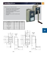
GIS MANUAL TROLLEY GHF 500K<br />
• For use with GCH250 and GCH500<br />
Electric Chain Hoists<br />
• Can be used as a standard beam trolley<br />
• Fits beam widths from 50-240mm<br />
• Safe Working Load – Max 500kg<br />
• Designed with a small amount of parts<br />
• Easy assembling and disassembling<br />
• Light aluminium die casting design<br />
• Strong, high resistant glass fibre<br />
reinforced plastic wheels<br />
• Adjustable to all I-beam widths<br />
FEM<br />
Classification<br />
1Bm<br />
(kg)<br />
1Am<br />
(kg)<br />
2m<br />
(kg)<br />
3m<br />
(kg)<br />
4m<br />
(kg)<br />
Spindle No. 1 Max flange<br />
thickness<br />
x=24 mm Beam Width Range<br />
GHF 500 K 500 500 500 400 320 Width of flange (mm) 50-240 Min flange width 50 mm 50-99mm 100-149mm 150-200mm 201-240mm<br />
B (mm) 30 Weight 2.5 kg<br />
L (mm) 183<br />
No. of tubes * length -<br />
Torque<br />
130 - 150Nm
GIS Power (Electric) Travel Trolley – EMFE Series<br />
Specification & prices - EMFE electric trolley series<br />
ISO<br />
(FEM)<br />
classification<br />
M3 (1Bm) M4 (1Am)<br />
150 s/h 180 s/h<br />
25% duty 30% duty<br />
M5 (2m)<br />
240 s/h<br />
40% duty<br />
M6 (3m)<br />
300 s/h<br />
50% duty<br />
M7 (4m)<br />
360 s/h<br />
60% duty<br />
Travelling<br />
speed<br />
Motor power<br />
(M3)<br />
3 x 400V<br />
50Hz<br />
(M3)<br />
Weight<br />
Electric<br />
or<br />
manual<br />
To be used<br />
with hoist<br />
type<br />
Beam Width Range<br />
15<br />
Type Capacity (kg) (m/min) (kW) (A) (kg)<br />
EMFE 50/N 1,000 800 630 630 500 12 0.25 0.8 27 Electric GCH250/500 50-99mm 100-149mm 150-200mm 201-240mm<br />
EMFE 50/NF 1,000 800 630 630 500 12/4 0.15/0.045 0.65/0.75 27 Electric GCH250/500<br />
EMFE 50/SF 800 800 630 630 500 20/6 0.15/0.045 0.65/0.75 27 Electric GCH250/500<br />
EMFE 150/N 2,000 2,000 1,600 1,600 1,250 12 0.25 0.8 31 Electric GCH1000 76-139mm 140-199mm 200-259mm 260-300mm<br />
EMFE 150/NF 2,000 2,000 1,600 1,600 1,250 12/4 0.15/0.045 0.65/0.75 31 Electric GCH1000<br />
EMFE 150/SF 1,600 1,600 1,600 1,600 1,250 20/6 0.15/0.045 0.65/0.75 31 Electric GCH1000<br />
EMFE 300/N 4,000 4,000 3,200 2’500 2,500 12 0.25 0.8 50 Electric GCH600/2000 56-119mm 120-179mm 180-239mm 240-300mm<br />
EMFE 300/NF 4,000 4,000 3,200 2,500 2,500 12/4 0.15/0.045 0.65/0.75 50 Electric GCH600/2000<br />
EMFE 300/SF 3,200 3,200 3,200 2,500 2,500 20/6 0.15/0.045 0.65/0.75 50 Electric GCH600/2000<br />
EMFE 500/N 5,000 4,000 3,200 3,200 2,500 12 2x0.25 2x0.8 57 Electric GCH2500 56-119mm 120-179mm 180-239mm 240-300mm<br />
EMFE 500/NF 5,000 4,000 3,200 3,200 2,500 12/4 2x0.15/0.045 2x0.65/0.75 57 Electric GCH2500<br />
EMFE 500/SF 4,000 4,000 3,200 3,200 2,500 20/6 2x0.15/0.045 2x0.65/0.75 57 Electric GCH2500<br />
DImensions (mm) - EMFE series<br />
Types e1 (mm) e2 (mm) f1 (mm) f2 (mm) f3 (mm) f4 (mm) f5 (mm) f6 (mm)<br />
EMFE 50 215 62 209 250 241 183 23 -<br />
EMFE 150 250 43 211 253 242 230 27 -<br />
EMFE 300 311 12 217 259 249 290 31 -<br />
EMFE 500 311 12 - 259 249 290 31 249<br />
Options<br />
• other flange widths<br />
• Selection of travel trolleys:<br />
GCH 250/500: EMFE 50<br />
GCH 1000: EMFE 150<br />
GCH 1600/2000: EMFE 300<br />
GCH 2500: EMFE 500<br />
Types g1(mm) g2 (mm) h2 (mm) Flange<br />
width<br />
(mm)<br />
EMFE 50/150/300/500<br />
GCH 250/1 GCH 250/2 GCH 500/1 GCH 500/2<br />
EMFE 50 49 167 418 457 426 466 50 - 99<br />
GCH 1000/1 GCH 1000/2<br />
EMFE 150 60 203 542 616 76 - 139<br />
GCH 1600/1 GCH 1600/2 GCH 2000/1 GCH 2000/2<br />
EMFE 300 55 218 637 719 637 719 120 - 179<br />
GCH 2500/1 GCH 2500/2<br />
EMFE 500 55 218 637 719 120-179<br />
EMFE 50/150<br />
EMFE 300/500
GIS GCH Electric Chain Hoist and trolley options<br />
16<br />
Types GCH<br />
Order Code<br />
SWL<br />
1Bm /<br />
M3<br />
Chain<br />
Falls<br />
Hoist<br />
Speed<br />
Chain<br />
Size<br />
Eye (Lug) Top Hook EXTRA PRICES FOR PUSH OR ELECTRIC TROLLEY<br />
(A) Suspension (B) Suspension Beam PUSH<br />
POWER (ELECTRIC) TRAVEL<br />
Width Travel<br />
(3 mtr <strong>Lift</strong>) (3 mtr <strong>Lift</strong>) Trolley<br />
m/min<br />
Duty Factor 25% m/min (d x p) mm O/C (£) O/C (£) (mm) 12 12/4 20/4<br />
GCH250/1N- 250 1 fall 8 4x12.3 E3 POA H3 POA 50-99 POA POA POA POA<br />
GCH250/1NF- 250 1 fall 8/2 4x12.3 E3 POA H3 POA 50-99 POA POA POA POA<br />
GCH250/1SF- 160 1 fall 12.5/3 4x12.3 E3 POA H3 POA 50-99 POA POA POA POA<br />
GCH250/1HF- 100 1 fall 20/5 4x12.3 E3 POA H3 POA 50-99 POA POA POA POA<br />
GCH250/2N- 500 2 fall 4 4x12.3 E3 POA H3 POA 50-99 POA POA POA POA<br />
GCH250/2NF- 500 2 fall 4/1 4x12.3 E3 POA H3 POA 50-99 POA POA POA POA<br />
GCH250/2SF- 320 2 fall 6.25/1.5 4x12.3 E3 POA H3 POA 50-99 POA POA POA POA<br />
GCH500/1N- 500 1 fall 8 5x15.3 E3 POA H3 POA 50-99 POA POA POA POA<br />
GCH500/1NF- 500 1 fall 8/2 5x15.3 E3 POA H3 POA 50-99 POA POA POA POA<br />
GCH500/1SF- 320 1 fall 12.5/3 5x15.3 E3 POA H3 POA 50-99 POA POA POA POA<br />
GCH500/1HF- 200 1 fall 20/5 5x15.3 E3 POA H3 POA 50-99 POA POA POA POA<br />
GCH500/2N- 1000 2 fall 4 5x15.3 E3 POA H3 POA 50-99 POA POA POA POA<br />
GCH500/2NF- 1000 2 fall 4/1 5x15.3 E3 POA H3 POA 50-99 POA POA POA POA<br />
GCH500/2SF- 630 2 fall 6.25/1.5 5x15.3 E3 POA H3 POA 50-99 POA POA POA POA<br />
GCH1000/1N- 1000 1 fall 8 7x22 E3 POA H3 POA 76-139 POA POA POA POA<br />
GCH1000/1NF- 1000 1 fall 8/2 7x22 E3 POA H3 POA 76-139 POA POA POA POA<br />
GCH1000/1SF- 1000 1 fall 16/4 7x22 E3 POA H3 POA 76-139 POA POA POA POA<br />
GCH1000/2N- 2000 2 fall 4 7x22 E3 POA H3 POA 76-139 POA POA POA POA<br />
GCH1000/2NF- 2000 2 fall 4/1 7x22 E3 POA H3 POA 76-139 POA POA POA POA<br />
GCH1000/2SF- 2000 2 fall 8/2 7x22 E3 POA H3 POA 76-139 POA POA POA POA<br />
GCH1600/1N- 1600 1 fall 8 9x27 E3 POA H3 POA 56-119 POA POA POA POA<br />
GCH1600/1NF- 1600 1 fall 8/2 9x27 E3 POA H3 POA 56-119 POA POA POA POA<br />
GCH1600/1SF- 1000 1 fall 12.5/3 9x27 E3 POA H3 POA 56-199 POA POA POA POA<br />
GCH1600/2N- 3200 2 fall 4 9x27 E3 POA H3 POA 56-119 POA POA POA POA<br />
GCH1600/2NF- 3200 2 fall 4/1 9x27 E3 POA H3 POA 56-119 POA POA POA POA<br />
GCH1600/2SF- 2000 2 fall 6.25/1.5 9x27 E3 POA H3 POA 56-199 POA POA POA POA<br />
GCH2000/1N- 2000 1 fall 8 10x28 E3 POA H3 POA 56-119 POA POA POA POA<br />
GCH2000/1NF- 2000 1 fall 8/2 10x28 E3 POA H3 POA 56-119 POA POA POA POA<br />
GCH2000/1SF- 1250 1 fall 12.5/3 10x28 E3 POA H3 POA 56-199 POA POA POA POA<br />
GCH2000/2N- 4000 2 fall 4 10x28 E3 POA H3 POA 56-119 POA POA POA POA<br />
GCH2000/2NF- 4000 2 fall 4/1 10x28 E3 POA H3 POA 56-119 POA POA POA POA<br />
GCH2000/2SF- 2500 2 fall 6.25/1.5 10x28 E3 POA H3 POA 56-199 POA POA POA POA<br />
GCH2500/1N- 2500 1 fall 6.4 10x28 E3 POA H3 POA 56-119 POA POA POA POA<br />
GCH2500/1NF- 2500 1 fall 6.4/1.6 10x28 E3 POA H3 POA 56-119 POA POA POA POA<br />
GCH2500/1SF- 1600 1 fall 10/2.5 10x28 E3 POA H3 POA 56-199 POA POA POA POA<br />
GCH2500/2N- 5000 2 fall 3.2 10x28 E3 POA H3 POA 56-119 POA POA POA POA<br />
GCH2500/2NF- 5000 2 fall 3.2/0.8 10x28 E3 POA H3 POA 56-119 POA POA POA POA<br />
GCH2500/2SF- 3200 2 fall 5/1.25 10x28 E3 POA H3 POA 56-199 POA POA POA POA<br />
Models comprising basic hoist with either eye or hook suspension, overload clutch, low voltage controls, upper & lower geared limits, limit stop, IP55, & 3<br />
metre height of lift as standard. Aditional heights of lift available on request.<br />
Chain Container and 2 Button (or 4 Button) Pendant with E-stop - Extra Price.<br />
Single and dual speed hoists available<br />
Power - 3 x 380/420V. 50Hz.<br />
Control Voltage: 42v.
GIS GCH Electric Chain Hoist and trolley options<br />
EXTRA PRICES FOR PUSH OR ELECTRIC TROLLEY EXTRA PRICES FOR PUSH OR ELECTRIC TROLLEY EXTRA PRICES FOR PUSH OR ELECTRIC TROLLEY<br />
Beam<br />
Width<br />
PUSH<br />
Travel<br />
Trolley<br />
POWER (ELECTRIC) TRAVEL Beam PUSH POWER (ELECTRIC) TRAVEL Beam PUSH POWER (ELECTRIC) TRAVEL<br />
Width Travel<br />
Width Travel<br />
m/min Trolley<br />
m/min Trolley<br />
m/min<br />
(mm) 12 12/4 20/4 (mm) 12 12/4 20/4 (mm) 12 12/4 20/4<br />
100-149 POA POA POA POA 150-200 POA POA POA POA 201-240 POA POA POA POA<br />
100-149 POA POA POA POA 150-200 POA POA POA POA 201-240 POA POA POA POA<br />
100-149 POA POA POA POA 150-200 POA POA POA POA 201-240 POA POA POA POA<br />
100-149 POA POA POA POA 150-200 POA POA POA POA 201-240 POA POA POA POA<br />
Additional<br />
<strong>Lift</strong><br />
Height<br />
Extra Cost<br />
2 Button<br />
Pendant H)<br />
Cable<br />
(P/M) (I)<br />
Extra Cost<br />
4 Button<br />
Pendant H)<br />
Cable<br />
(P/M) (I)<br />
(P/M) (G) (std 1.8m) (std 1.8m) 0<br />
(£) (£) (£) (£) (£)<br />
POA POA POA POA POA<br />
POA POA POA POA POA<br />
POA POA POA POA POA<br />
POA POA POA POA POA<br />
17<br />
100-149 POA POA POA POA 150-200 POA POA POA POA 201-240 POA POA POA POA<br />
100-149 POA POA POA POA 150-200 POA POA POA POA 201-240 POA POA POA POA<br />
100-149 POA POA POA POA 150-200 POA POA POA POA 201-240 POA POA POA POA<br />
POA POA POA POA POA<br />
POA POA POA POA POA<br />
POA POA POA POA POA<br />
100-149 POA POA POA POA 150-200 POA POA POA POA 201-240 POA POA POA POA<br />
100-149 POA POA POA POA 150-200 POA POA POA POA 201-240 POA POA POA POA<br />
100-149 POA POA POA POA 150-200 POA POA POA POA 201-240 POA POA POA POA<br />
100-149 POA POA POA POA 150-200 POA POA POA POA 201-240 POA POA POA POA<br />
POA POA POA POA POA<br />
POA POA POA POA POA<br />
POA POA POA POA POA<br />
POA POA POA POA POA<br />
100-149 POA POA POA POA 150-200 POA POA POA POA 150-200 POA POA POA POA<br />
100-149 POA POA POA POA 150-200 POA POA POA POA 150-200 POA POA POA POA<br />
100-149 POA POA POA POA 150-200 POA POA POA POA 150-200 POA POA POA POA<br />
POA POA POA POA POA<br />
POA POA POA POA POA<br />
POA POA POA POA POA<br />
140-199 POA POA POA POA 200-259 POA POA POA POA 260-320 POA POA POA POA<br />
140-199 POA POA POA POA 200-259 POA POA POA POA 260-320 POA POA POA POA<br />
140-199 POA POA POA POA 200-259 POA POA POA POA 260-320 POA POA POA POA<br />
POA POA POA POA POA<br />
POA POA POA POA POA<br />
POA POA POA POA POA<br />
140-199 POA POA POA POA 200-259 POA POA POA POA 260-320 POA POA POA POA<br />
140-199 POA POA POA POA 200-259 POA POA POA POA 260-320 POA POA POA POA<br />
140-199 POA POA POA POA 200-259 POA POA POA POA 260-320 POA POA POA POA<br />
POA POA POA POA POA<br />
POA POA POA POA POA<br />
POA POA POA POA POA<br />
120-179 POA POA POA POA 180-239 POA POA POA POA 240-300 POA POA POA POA<br />
120-179 POA POA POA POA 180-239 POA POA POA POA 240-300 POA POA POA POA<br />
120-179 POA POA POA POA 180-239 POA POA POA POA 240-300 POA POA POA POA<br />
POA POA POA POA POA<br />
POA POA POA POA POA<br />
POA POA POA POA POA<br />
120-179 POA POA POA POA 180-239 POA POA POA POA 240-300 POA POA POA POA<br />
120-179 POA POA POA POA 180-239 POA POA POA POA 240-300 POA POA POA POA<br />
120-179 POA POA POA POA 180-239 POA POA POA POA 240-300 POA POA POA POA<br />
POA POA POA POA POA<br />
POA POA POA POA POA<br />
POA POA POA POA POA<br />
120-179 POA POA POA POA 180-239 POA POA POA POA 240-300 POA POA POA POA<br />
120-179 POA POA POA POA 180-239 POA POA POA POA 240-300 POA POA POA POA<br />
120-179 POA POA POA POA 180-239 POA POA POA POA 240-300 POA POA POA POA<br />
POA POA POA POA POA<br />
POA POA POA POA POA<br />
POA POA POA POA POA<br />
120-179 POA POA POA POA 180-239 POA POA POA POA 240-300 POA POA POA POA<br />
120-179 POA POA POA POA 180-239 POA POA POA POA 240-300 POA POA POA POA<br />
120-179 POA POA POA POA 180-239 POA POA POA POA 240-300 POA POA POA POA<br />
POA POA POA POA POA<br />
POA POA POA POA POA<br />
POA POA POA POA POA<br />
120-179 POA POA POA POA 180-239 POA POA POA POA 240-300 POA POA POA POA<br />
120-179 POA POA POA POA 180-239 POA POA POA POA 240-300 POA POA POA POA<br />
120-179 POA POA POA POA 180-239 POA POA POA POA 240-300 POA POA POA POA<br />
POA POA POA POA POA<br />
POA POA POA POA POA<br />
POA POA POA POA POA<br />
120-179 POA POA POA POA 180-239 POA POA POA POA 240-300 POA POA POA POA<br />
120-179 POA POA POA POA 180-239 POA POA POA POA 240-300 POA POA POA POA<br />
120-179 POA POA POA POA 180-239 POA POA POA POA 240-300 POA POA POA POA<br />
POA POA POA POA POA<br />
POA POA POA POA POA<br />
POA POA POA POA POA
GIS Chain handy & Telescopic handy<br />
18<br />
These hoists are designed to ease repetitive manual handling,<br />
the Chain Handy & Telescopic Handy work perfectly with<br />
articulated jib cranes and KB Track Crane Systems.<br />
The GIS Handy is a versatile hoisting appliance that has been<br />
designed with a bracket for easy mounting of manipulator<br />
arms, vacuum and lifting systems for repetitive handling of<br />
many types of loads.<br />
The GIS Chain Handy allows product positioning through the<br />
2 speed toggle switch and flexible hand guide control, in a<br />
comfortable and efficient way. This product has standard left<br />
and right hand operation and is available for safe lifting up<br />
to 500kg SWL.<br />
The GIS Telescopic Handy allows accurate product<br />
positioning through the 2 speed toggle switch and rigid<br />
telescopic guide system. This product has standard left and<br />
right hand operation and is available for safe lifting up to<br />
250kg. The GIS Telescopic Handy allows the controlled and<br />
perfected handling of goods. The telescopic Handy is so rigid<br />
and smooth you can even transport liquids.<br />
Four standard telescopic lifting heights are available from<br />
800mm to 2000mm, all of which can have eccentric loads.<br />
The controls for either Handy unit are mounted adjacent to<br />
the load to provide safe handling and maximum operator<br />
control. The push button station will accept a load hook or a<br />
variety of other suspension units.<br />
All Handy hoists have fast two-speed lifting, high duty<br />
factors and are fitted with an electrical limit switch and<br />
slipping clutch to prevent overloading.<br />
Telescopic<br />
handy<br />
handy<br />
standard<br />
GCHHTD<br />
fem<br />
Classification<br />
2m 3m 4m<br />
<strong>Lift</strong>ing Motor 3x220V 3x380V 5x420V Weight<br />
Switchings /h 240 300 360 speed power 50Hz 50Hz 50Hz uncompl<br />
Duty Factor % 40 50 60<br />
kg kg kg m/min. kW (2m) A (2m) A (2m) A (2m) kg<br />
GCHHK 500<br />
/NF<br />
GCHHK 500<br />
/SF<br />
GCHHK 500<br />
/HF<br />
250 250 200 8/2 0.4/0.07 51/2.8 2.9/1.6 2.8/1.6 27<br />
200 160 125 12.5/3 0.59/0.09 5.6/2.8 3.2/1.6 2.9/1.5 27<br />
125 100 80 20/5 0.59/0.09 5.6/2.8 3.2/1.6 2.7/1.5 27<br />
DImensions (mm)<br />
<strong>Lift</strong>ing<br />
Height<br />
1200 1500 2000<br />
a b c a b c a b c<br />
GCHHTD 500 1370 2570 185÷690 1370 2870 185÷690 1620 3620 185÷1100<br />
Please consult us for eccentric loading
LTM DUO Hoisting System<br />
• Different lengths and lifting centres available<br />
• Ideal for lifting long loads - steel reels, log lifting devices for the paper<br />
industry, rollers for the printing industry, coating/ dipping of baskets,<br />
raising and lowering screens in the entertainment industry<br />
• Eye/Hook or trolley suspension on hoist<br />
• Operate 2 hoists synchronously via one pendant handset<br />
• Available with radio control<br />
• Option for supply of enclosed KB Monorail or Crane Track Systems<br />
• <strong>Lift</strong>ing Capacity from 125kg to 1000kg<br />
• Available in single speed and two speed<br />
19
GIS GCHR food grade hoist<br />
20<br />
The GCHR food grade hoist is well-suited for lifting applications in food or pharmaceutical<br />
production, wash-down, environmentally-controlled and harsh corrosive processing<br />
environments. Available in standard capacities up to 1250kg, the GCHR food grade chain hoist<br />
features highly sealed IP65 bearings and covers, food grade lubrication and stainless steel hooks,<br />
chain and a special Electrophoresis KTL / ATL plated hoist body.<br />
Chain lubrication – CALOR USDA H1, this is resistant to water washout and ensures excellent<br />
lubrication for machinery over a wide range and operating temperatures of -20 to 150 degrees<br />
centigrade. This lubrication is a semi-fluid grease suitable for use in food factory applications<br />
where the risk of food contact exists.<br />
GIS GCHR<br />
• Stainless steel components - chain, single fall<br />
hook clamp, double fall hook clamp, chain guide,<br />
load hook, hook and eyebolt suspension<br />
• High alloy steel components - chain wheel<br />
• Aluminium components: casing, limit stop assembly<br />
(screws in stainless steel A2)<br />
• Colour: black, KTL plated, resistant against water,<br />
oils, scant alkalis and acids<br />
• Gear grease: food grade<br />
• Geared limit switch for highest and lowest<br />
hook position<br />
• Control pendant<br />
GCHR500<br />
<strong>Lift</strong>ing<br />
Capacity<br />
<strong>Lift</strong>ing<br />
Capacity<br />
No of Chain<br />
Falls<br />
<strong>Lift</strong>ing Speed Motor Power 3 x 400V 50Hz Weight Extra Weight <strong>Lift</strong>ing Height<br />
FEM Classification 1Am 2m Main Speed Creep Speed Complete Per Metre <strong>Lift</strong> (standard)<br />
Duty Factor 30% 40% (for 3m <strong>Lift</strong>)<br />
Type (kg) (kg) (m/min) (m/min) (kW) (A) (kg) (kg) (m)<br />
GCHR500/1N 320 250 1 8 --- 0.72 2.1 20 0.52 3<br />
GCHR500/1NF 320 250 1 8 2 0.72/0.18 2.9/3.0 22.5 0.52 3<br />
GCHR500/2N 630 500 2 4 --- 0.72 2.1 20 0.52 3<br />
GCHR500/2NF 630 500 2 4 1 0.72/0.18 2.9/3.0 22.5 0.52 3<br />
Additional Equipment Type Order Code<br />
Geared limit switch with e-stop<br />
MP9401.3018.3<br />
Additional cost top hook suspension GCHR500 MP9401.4503.3<br />
Chain bucket GKM500/6, KS 9401.3010.1<br />
Chain bucket GKM500/12, KS 9401.3011.1<br />
Chain bucket GKM500/16R 9401.4508.2<br />
GCHR1000<br />
<strong>Lift</strong>ing<br />
Capacity<br />
<strong>Lift</strong>ing<br />
Capacity<br />
No of Chain<br />
Falls<br />
<strong>Lift</strong>ing Speed Motor Power 3 x 400V 50Hz Weight Extra Weight <strong>Lift</strong>ing Height<br />
FEM Classification 1Am 2m Main Speed Creep Speed Power Complete Per Metre <strong>Lift</strong> (standard)<br />
Duty Factor 30% 40% (for 3m <strong>Lift</strong>)<br />
Type (kg) (kg) (m/min) (m/min) (kW) (A) (kg) (kg) (m)<br />
GCHR1000/1N 630 500 1 8 --- 0.91 3.1 36 1.04 3<br />
GCHR1000/1NF 630 500 1 8 2 0.91/0.23 2.8/2.6 40 1.04 3<br />
GCHR1000/2N 1250 1000 2 4 --- 0.91 3.1 38 1.04 3<br />
GCHR1000/2NF 1250 1000 2 4 1 0.91/0.23 2.8/2.6 42 1.04 3<br />
Additional Equipment Type Order Code<br />
Geared limit switch with e-stop<br />
MP9401.3018.3<br />
Additional cost hook suspension GCHR1000 MP9405.4509.3<br />
Chain Bucket GKM 1000/8KS 9405.3044.1<br />
Chain Bucket GKMR 1000/20 9405.4511.2
ATEX dust or gas proof electric chain hoist<br />
21<br />
II 3 D IP 65 T 130ºc<br />
Equipment group II<br />
Equipment category 3<br />
Zone 22 (D)<br />
Temperature =
Radio Control Electric Chain Hoists Systems<br />
22<br />
Radio remote system for hoisting applications compliant with safety standard Cat.3 CE<br />
EN-954-1 or EN 13849. Available receiver power supplies (24-48-155 and 230v AC)<br />
with a maximum of 6 output relays.<br />
• Tactile and high sensitivity keyboard<br />
• Ergonomic transmitter with one or two step pushbuttons<br />
• Automatic working channel slection<br />
• Auto ID teaching function - Simple and easy to use<br />
• Remotely programmable receiver’s outputs using the programmer module<br />
(radio remote programmer module)<br />
• Can backup or restore system’s configurations<br />
• With plugin optional pendant<br />
• Single and multi hoist control systems<br />
• As standard all LTM radio control systems are supplied with secondary<br />
wired control system
Wind Turbine Hoist (GCH Wind)<br />
With a small body and confined dimensions, standard lifting height of up to 120 metres<br />
makes this hoist ideal for wind turbines. High lifting speeds and a safety overload clutch<br />
as overload protection guarantees a safe and efficient operation.<br />
The chain guide is composed from weather resistant material to ensure long a long life<br />
in harsh environments. The tail end of chain can be guided out of the way via reinforced<br />
tube; this allows lower headroom with the tail end of the chain being diverted safely.<br />
High duty motors, specially developed for an industry leader wind turbine manufacture<br />
this makes the GCH Winch ideal for extremely high lifts up to 120 metres. The hook cone<br />
covers the lover hook block to avoid accidental hook ups.<br />
23<br />
The GCH Wind can be customised for almost any wind turbine lifting application.<br />
• GCH500/1HFS.2M<br />
• Motor with Klixon<br />
• lifting height up to 120 m<br />
• Power supply 3 x 400 V 50 Hz<br />
• Capacity 250 kg<br />
• <strong>Lift</strong>ing speed 16/4 m/min.<br />
• Geared limit switch with automatic change from<br />
fast to slow speed and external switch<br />
• Control pendant with 1.0 m cable<br />
• Low voltage 42 V<br />
• with hook cap<br />
• with connecting cable with CEE plug
OVERVIEW OF GIS KB CRANE & MONORAIL SYSTEMS<br />
24<br />
Single bridge suspended crane Double bridge suspended crane Monorail Slewing Pillar Jib crane<br />
Single bridge suspended crane<br />
• All-round goods transportation, up to 1,250 kg (optional 2,000 kg)<br />
• For normal headroom<br />
Double bridge suspended crane<br />
• All-round goods transportation, up to 1,250 kg (optional 2,000 kg)<br />
• For lower headroom<br />
Monorail with bends, switches and turntables<br />
• To link workstations, up to 1,550 kg<br />
• Flexible line routing thanks to bends<br />
• Individual lines can be connected using slide switches and turntables<br />
For use when ceilings have insufficient load-bearing capacity or<br />
as an addition to your suspended crane. To reduce machine<br />
set-up times and waiting times.<br />
Slewing pillar JIB crane<br />
Up to 1,000 kg, max. rotational field 270°, jib arm length up<br />
to 5 m. Can also be supplied as a slewing articulated crane<br />
(up to 250 kg).<br />
Slewing wall JIB crane<br />
The alternative when it is not possible to erect a pillar.<br />
Installation on an existing pillar/wall. Technical data as<br />
slewing pillar crane.<br />
Handy chain and telescope models<br />
Economic lifting of small loads. A valuable way of making<br />
work easier, in combination with a slewing or suspended<br />
crane. Can handle offset loads: control unit directly on the<br />
load hook. (see page 18)<br />
GIS switch/turntable<br />
• For accurate transitions between tracks<br />
• Variants: slide switches/turntables with internal or<br />
external conductor lines<br />
GISKB bends<br />
• To reach individual workstations with total accuracy<br />
• To make optimum use of confined spaces<br />
Locking switches<br />
• Cost-saving technology to cover partial working areas<br />
• No need for a complete crane system<br />
• Function: locking and traversing into a lateral monorail<br />
Internal conductor line<br />
• The elegant alternative to trailing cables or looped wires<br />
• Placed inside the profile (for mechanical protection)<br />
• Ideal in confined spaces<br />
Benefits to you:<br />
• Reasonably priced, thanks to series-produced<br />
standard parts and rolled profiles<br />
• Simple to install, all components can be screwed/bolted<br />
• Manual or electrical crane/trolley movement<br />
• Low noise level thanks to plastic guide rollers<br />
• Various power supplies<br />
• Guaranteed conversion/extension of existing crane systems
OVERVIEW OF GIS KB crane system<br />
Components<br />
• Four profile sizes<br />
• Connection plates on both ends<br />
• Standard profile lengths,<br />
between 1 m and 8 m<br />
• Special lengths to order<br />
Your benefits:<br />
• Excellent performance thanks to high<br />
load-carrying capacity<br />
• Simple to install, thanks to optimised design<br />
• Competitively priced, thanks to standard<br />
rolled profiles<br />
25<br />
Optimal profile size<br />
Use the table below to determine the optimal profile size,<br />
depending on the load P and the span W.<br />
Basis: Max. permissible deflection = W/400, Max stress = 180 N/M2.<br />
<strong>Lift</strong>ing gear weight: 25 kg (up to load capacity of 500 kg), 50 kg (for load capacity over 500 KG)<br />
Load<br />
capacity<br />
GIS KB I Span (mm) GIS KB II Span (mm) Load<br />
capacity<br />
Track only | NP 120 | NP 160 | NP 180 MR Track only | NP 120 | NP 160 | NP 180 MR<br />
100 kg 4,7 5,9 7,8 7,8 7,8 7,8 7,8 7,8 7,5 7,2 7,8 7,8 7,8 7,8 7,8 7,8 7,8 100 kg<br />
125 kg 4,4 5,6 6,9 6,9 125 kg<br />
160 kg 4,0 5,3 6,1 6,4 7,8 160 kg<br />
200 kg 3,7 4,9 5,6 6,0 7,5 200 kg<br />
250 kg 3,4 4,6 7,4 5,0 5,6 7,1 250 kg<br />
320 kg 3,1 4,2 6,8 4,2 5,1 6,6 7,6 320 kg<br />
400 kg 2,8 3,8 6,3 3,3 4,7 6,2 7,6 6,8 400 kg<br />
500 kg 2,5 3,5 5,5 7,5 7,5 2,9 4,3 5,7 7,1 5,8 500 kg<br />
630 kg 2,0 3,2 4,5 7,0 6,3 7,3 2,3 3,8 5,2 6,4 4,5 630 kg<br />
800 kg 2,8 6,4 3,2 4,8 5,2 7,7 7,0 3,6 800 kg<br />
1,000 kg 2,5 5,6 7,5 2,7 4,3 4,3 7,1 5,8 6,6 3,1 1,000 kg<br />
1,250 kg 2,1 4,6 6,4 7,4 2,7 3,9 3,5 6,5 4,7 5,4 2,6 1,250 kg<br />
With reinforcement<br />
Option: Aluminium track also available - see page 28<br />
Without reinforcement<br />
Single crane with bridge span W (m)<br />
Double crane with bridge span W (m)<br />
Load Capacity (kg) GISKB III GISKB IV<br />
Load Capacity (kg) GISKB III GISKB IV<br />
100 8.2 10.5<br />
125 7.8 10.2<br />
160 7.4 9.9<br />
200 7.0 9.3<br />
250 6.5 8.9<br />
320 6.0 8.2<br />
400 5.5 7.7<br />
500 5.1 7.2<br />
630 4.6 6.6<br />
800 4.1 5.9<br />
1000 3.6 5.4<br />
1250 2.9 4.9<br />
1600 2.4 4.0<br />
100 9.4 11.8<br />
125 9.1 11.6<br />
160 8.7 11.3<br />
200 8.5 11.0<br />
250 8.1 10.8<br />
320 7.6 10.1<br />
400 7.2 9.7<br />
500 6.7 9.3<br />
630 6.2 8.5<br />
800 5.7 8.0<br />
1000 5.2 7.2<br />
1250 4.7 6.7<br />
1600 4.2 6.0
OVERVIEW OF GIS KB crane & monorail systems<br />
26<br />
Suspension options<br />
Short, rigid (fig 4)<br />
• The rigid suspension can only be supplied in the short version<br />
• Reduced headroom dimension<br />
Short, pendulating, adjustable (fig 1)<br />
• Ball pins and nuts are screwed together directly<br />
• Pendulation movements max. 10°<br />
• Height adjustable by ± 7.5 mm<br />
Distanced, pendulating, adjustable (fig 2)<br />
• Distanced suspension, variable length<br />
• Height differences of ± 15 mm can be adjusted out<br />
fig 4<br />
Distanced, pendulating, adjustable, braced (fig 3)<br />
• > distance 0.5 m: bracing is mandatory<br />
• Longitudinal bracing: both ends of track<br />
• Transverse bracing: on one side, every 2nd suspension<br />
Lateral suspension<br />
• Lateral installation on wood or concrete beam<br />
fig 1<br />
fig 2 fig 3<br />
Trolleys<br />
• Components designed in galvanized steel<br />
• Use is guaranteed for longitudinal and transverse movements<br />
• Load partition is ensured by 2 trolleys<br />
• On the saddle of the double crane bridge: 4 trolleys in use<br />
• Drive: manual or electrical<br />
2 trolleys with traverse<br />
Benefits to you:<br />
• Silent running is maximised thanks to plastic guide rollers<br />
• Ideal for awkward and critical loads<br />
• Easily converted from manual to electrical operation<br />
• Gentle start-up and braking thanks to the frequency inverter<br />
Rolling apparatus<br />
Electrical drive<br />
4 trolleys with saddle<br />
(to reduce headroom)
OVERVIEW OF GIS KB crane & monorail systems - electronics & bends<br />
Electrics<br />
Types of power supply<br />
• 3 phase, 380/400V 50Hz<br />
• Or for your operating electrical supply<br />
27<br />
GISKB power supplies complete<br />
• Cable carriage, traction limit, connector, C-rail stop ...<br />
Conventional conductor line<br />
4 types of longitudinal and transverse power supply:<br />
• Trailing cable<br />
• C-rail<br />
• Conventional enclosed conductor line<br />
• Conductor line inside profile<br />
GISKB II ST internal conductor line<br />
• Flexible, universal<br />
• Attractive design<br />
• For universal use<br />
• Load: 25A with max.100 m profile length<br />
• Trolley design as for GISKB I (up to 800 kg)<br />
Trailing cable<br />
C-rail<br />
Bends<br />
• Can be supplied with angles of 30° and 45°<br />
• Radius: 1m<br />
• End plate at both ends<br />
• Suspension at 2 points<br />
• Conductor line bends can be obtained<br />
with same angles as profile bends<br />
Slide switches/turntables<br />
• Profiles are moved manually or electrically<br />
• Manual: with traction cable<br />
• Electrical: with 2-button control switch<br />
• Option: supplied with conductor lines
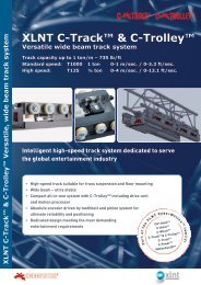
GIS KB Aluminium Track<br />
28<br />
Single crane with bridge span W (m)<br />
Double crane with bridge span W (m)<br />
Load Capacity (kg) GISKB ALU S GISKB ALU M GISKB ALU L<br />
Load Capacity (kg) GISKB ALU S GISKB ALU M GISKB ALU L<br />
50 4.7 6.8 7.8<br />
80 4.1 6.2 7.8<br />
100 3.8 5.8 7.8<br />
125 3.5 5.4 7.4<br />
160 3.2 5.0 6.8<br />
200 2.9 4.5 6.3<br />
250 - 4.2 5.8<br />
320 - 3.7 5.2<br />
400 - - 4.7<br />
500 - - 4.3<br />
630 - - 3.8<br />
50 5.9 7.8 7.8<br />
80 5.3 7.7 7.8<br />
100 5.0 7.3 7.8<br />
125 4.7 7.0 7.8<br />
160 4.3 6.5 7.8<br />
200 4.0 6.0 7.8<br />
250 - 5.6 7.6<br />
320 - 5.1 7.0<br />
400 - 4.7 6.4<br />
500 - - 5.9<br />
630 - - 5.3
OVERVIEW OF GIS KB crane & monorail systems<br />
29
30<br />
OVERVIEW OF GIS KB crane & monorail systems
Able forge manufacturing INC Products<br />
<strong>Lift</strong> <strong>Turn</strong> <strong>Move</strong> Ltd, Version 2, August 2012<br />
Specifications<br />
Hoists / Track / Winches / Jacks / Pulleys / CLAMPS - ALL IN ONE PLACE<br />
<strong>Lift</strong>ing Equipment and Systems for Industrial and Entertainment Industries
ABLE Brand Chain Block Model CB-II - Fitted with G80 plated Chains<br />
32<br />
Technical Benefits<br />
• Superior Grade 100 load chain –<br />
Wafios link Din standard<br />
• Forged and Heat Treated load hooks<br />
with batch traceability and stretch<br />
indicators<br />
• Double pawls supporting failsafe<br />
brake mechanism. Even if<br />
one of the two pawls becomes<br />
unserviceable, the other will still<br />
remain operative, and the brake<br />
system remains secure.<br />
• Asbestos free Brake Linings<br />
• Forged Hook Safety Latch with<br />
manufacture mark<br />
• Individually proof load tested to<br />
1.5 X WLL with individual serial<br />
number<br />
• Lightweight yet durable<br />
• Steel frame construction is rugged yet<br />
lightweight and easy to handle<br />
• Low maintenance<br />
• Enclosed housing allows outdoor use.<br />
• The load brake requires no lubrication<br />
Quality features<br />
• Wheel cover with guide slots against<br />
jamming and slipping of chain<br />
• Forged swivel hooks with latches<br />
prevent twisting of chain and reduce<br />
unintentional unhooking of the unit<br />
or the load<br />
• Chain guide and stripper ensure proper<br />
fit of chain over pocket wheel<br />
• Two-stage gear reduction with hardened<br />
gears and pinion
ABLE Brand Chain Block Model CB-II - Fitted with G80 ABLE Chains<br />
ABLE Brand Chain Block Model CB-II - Fitted with<br />
G80 ABLE Zinc Chains<br />
Description Capacity Height of <strong>Lift</strong> No. of Falls<br />
LTM Product Code (t) (m)<br />
AB/CB250/3 ABLE CB SERIES HAND CHAIN BLOCK 0.25 3 1<br />
33<br />
DImensions (mm)<br />
Product<br />
Code<br />
AB/CB-II /005/3 ABLE CB-II SERIES HAND CHAIN BLOCK 0.5 3 1<br />
AB/CB-II /005/6 ABLE CB-II SERIES HAND CHAIN BLOCK 0.5 6 1<br />
AB/CB-II /005/9 ABLE CB-II SERIES HAND CHAIN BLOCK 0.5 9 1<br />
AB/CB-II /005/12 ABLE CB-II SERIES HAND CHAIN BLOCK 0.5 12 1<br />
AB/CB-II /010/3 ABLE CB-II SERIES HAND CHAIN BLOCK 1.0 3 1<br />
AB/CB-II /010/6 ABLE CB-II SERIES HAND CHAIN BLOCK 1.0 6 1<br />
AB/CB-II /010/9 ABLE CB-II SERIES HAND CHAIN BLOCK 1.0 9 1<br />
AB/CB-II /010/12 ABLE CB-II SERIES HAND CHAIN BLOCK 1.0 12 1<br />
AB/CB-II /015/3 ABLE CB-II SERIES HAND CHAIN BLOCK 1.5 3 1<br />
AB/CB-II /015/6 ABLE CB-II SERIES HAND CHAIN BLOCK 1.5 6 1<br />
AB/CB-II /015/9 ABLE CB-II SERIES HAND CHAIN BLOCK 1.5 9 1<br />
AB/CB-II /015/12 ABLE CB-II SERIES HAND CHAIN BLOCK 1.5 12 1<br />
AB/CB-II /020/3 ABLE CB-II SERIES HAND CHAIN BLOCK 2.0 3 1<br />
AB/CB-II /020/6 ABLE CB-II SERIES HAND CHAIN BLOCK 2.0 6 1<br />
AB/CB-II /020/9 ABLE CB-II SERIES HAND CHAIN BLOCK 2.0 9 1<br />
AB/CB-II /020/12 ABLE CB-II SERIES HAND CHAIN BLOCK 2.0 12 1<br />
AB/CB-II /030/3 ABLE CB-II SERIES HAND CHAIN BLOCK 3.0 3 2<br />
AB/CB-II /030/6 ABLE CB-II SERIES HAND CHAIN BLOCK 3.0 6 2<br />
AB/CB-II /030/9 ABLE CB-II SERIES HAND CHAIN BLOCK 3.0 9 2<br />
AB/CB-II /030/12 ABLE CB-II SERIES HAND CHAIN BLOCK 3.0 12 2<br />
AB/CB-II /050/3 ABLE CB-II SERIES HAND CHAIN BLOCK 5.0 3 2<br />
AB/CB-II /050/6 ABLE CB-II SERIES HAND CHAIN BLOCK 5.0 6 2<br />
AB/CB-II /050/9 ABLE CB-II SERIES HAND CHAIN BLOCK 5.0 9 2<br />
AB/CB-II /050/12 ABLE CB-II SERIES HAND CHAIN BLOCk 5.0 12 2<br />
AB/CB-II /100/3 ABLE CB-II SERIES HAND CHAIN BLOCK 10.0 3 4<br />
AB/CB-II /100/6 ABLE CB-II SERIES HAND CHAIN BLOCK 10.0 6 4<br />
AB/CB-II /100/9 ABLE CB-II SERIES HAND CHAIN BLOCK 10.0 9 4<br />
AB/CB-II /100/12 ABLE CB-II SERIES HAND CHAIN BLOCK 10.0 12 4<br />
AB/CB-II /200/3 ABLE CB-II SERIES HAND CHAIN BLOCK 20.0 3 8<br />
AB/CB-II /200/6 ABLE CB-II SERIES HAND CHAIN BLOCK 20.0 6 8<br />
AB/CB-II /200/9 ABLE CB-II SERIES HAND CHAIN BLOCK 20.0 9 8<br />
AB/CB-II /200/12 ABLE CB-II SERIES HAND CHAIN BLOCK 20.0 12 8<br />
AB/CB-II /300/3 ABLE CB-II SERIES HAND CHAIN BLOCK 30.0 3 12<br />
AB/CB-II /300/6 ABLE CB-II SERIES HAND CHAIN BLOCK 30.0 6 12<br />
AB/CB-II /300/9 ABLE CB-II SERIES HAND CHAIN BLOCK 30.0 9 12<br />
AB/CB-II /300/12 ABLE CB-II SERIES HAND CHAIN BLOCK 30.0 12 12<br />
Capacity Pull full load Load chain<br />
dia<br />
Dimensions (mm)<br />
Weight - 3m<br />
lift<br />
Extra weight<br />
per metre<br />
lift<br />
AB/CB-II (t) (n) (mm) A B C D H (kg) (kg)<br />
AB/CB-II /005 0.5 221 6 125 111 24 134 255 8.0 1.7<br />
AB/CB-II /010 1.0 304 6 147 126 28 154 306 10.0 1.7<br />
AB/CB-II /015 1.5 343 8 183 141 34 192 368 16.0 2.3<br />
AB/CB-II /020 2.0 294 8 215 163 38 224 396 27.0 5.3<br />
AB/CB-II /030 3.0 343 8 183 141 38 192 486 24.0 3.7<br />
AB/CB-II /050 5.0 383 10 215 163 48 224 616 36.0 5.3<br />
AB/CB-II /100 10.0 392 10 360 163 64 224 700 68.0 9.7<br />
AB/CB-II /200 20.0 392 10 585 191 82 224 1000 156.0 19.4<br />
AB/CB-II /300 30.0 435 x 2 10 705 485 75 85 1200 135.0 28.4
ABLE Brand Chain Block Model CB-I<br />
34<br />
Technical Benefits<br />
Load chains are approved to DIN 5684, one of the world’s most rigid standards. This is the special heat<br />
treated load chain of ISO Grade T (900N/mm2) whose tensile strength surpasses ISO T class.<br />
• Meets requirements of EN13157<br />
• Load sheave with sealed<br />
roller bearing<br />
Double pawls (on 1.0t and above) supporting fail-safe brake mechanism<br />
Even if by any chance one of the two pawls becomes unserviceable, the other will still remain operative, and<br />
the brake system remains secure.<br />
Bottom hook with thrust bearing<br />
The thrust bearing enables the lifted load to be moved in any direction without subjecting it to stress<br />
Hooks of easier handling shape<br />
The opening of the hooks has been made wider for easier handling and working.<br />
Durable and solid enclosure<br />
The tough gear casing, reinforced with four ribs and four knock pins, provides accurate gear centering and<br />
high mechanical efficiency.<br />
Roll-edge hand wheel cover<br />
This provides smooth operation of the hand chain when pulled sideways.<br />
Product<br />
Code<br />
<strong>Lift</strong>ing<br />
Capacity<br />
Pulling<br />
Effort<br />
No. of chain<br />
falls<br />
Load chain<br />
dia<br />
Dimensions (mm)<br />
Weight 3m<br />
lift<br />
Extra weight<br />
per metre<br />
lift<br />
AB/CB-I (t) (kg) (mm) A B C D (kg) (kg)<br />
AB/CB-I/005 0.5 16 1 5.0 127 144 285 27 9.1 1.50<br />
AB/CB-I/010 1.0 24 1 6.3 147 157 315 30 12.0 1.84<br />
AB/CB-I/015 1.5 28 1 7.1 179 174 340 34 13.8 2.25<br />
AB/CB-I/020 2.0 32 1 8.0 179 204 380 37 21.6 2.50<br />
AB/CB-I/020A 2.0(A) 30 2 6.3 147 174 380 37 20.4 2.78<br />
AB/CB-I/030 3.0 32 2 7.1 179 206 475 43 21.0 3.30<br />
AB/CB-I/050 5.0 36 2 9.0 179 263 635 46 37.5 4.74<br />
AB/CB-I/100 10.0 38 4 9.0 179 367 760 67 59.5 8.38<br />
AB/CB-I/150 15.0 38x2 6 9.0 207 754 850 84 125.0 11.92<br />
AB/CB-I/200 20.0 38x2 8 9.0 207 873 870 96 145.6 16.76
ABLE Brand Chain Block Model CB-I<br />
ABLE Brand Chain Block Model CB-I - Fitted<br />
with G80 Chains<br />
Description <strong>Lift</strong>ing Capacity Height of <strong>Lift</strong> No. of Chain Falls<br />
LTM Product Code (t) (m)<br />
AB/CB-I/005/3 ABLE CB-1 SERIES HAND CHAIN BLOCK 0.5 3 1<br />
AB/CB-I/005/6 ABLE CB-1 SERIES HAND CHAIN BLOCK 0.5 6 1<br />
AB/CB-I/005/9 ABLE CB-1 SERIES HAND CHAIN BLOCK 0.5 9 1<br />
AB/CB-I/005/12 ABLE CB-1 SERIES HAND CHAIN BLOCK 0.5 12 1<br />
35<br />
AB/CB-I/010/3 ABLE CB-1 SERIES HAND CHAIN BLOCK 1.0 3 1<br />
AB/CB-I/010/6 ABLE CB-1 SERIES HAND CHAIN BLOCK 1.0 6 1<br />
AB/CB-I/010/9 ABLE CB-1 SERIES HAND CHAIN BLOCK 1.0 9 1<br />
AB/CB-I/010/12 ABLE CB-1 SERIES HAND CHAIN BLOCK 1.0 12 1<br />
AB/CB-I/015/3 ABLE CB-1 SERIES HAND CHAIN BLOCK 1.5 3 1<br />
AB/CB-I/015/6 ABLE CB-1 SERIES HAND CHAIN BLOCK 1.5 6 1<br />
AB/CB-I/015/9 ABLE CB-1 SERIES HAND CHAIN BLOCK 1.5 9 1<br />
AB/CB-I/015/12 ABLE CB-1 SERIES HAND CHAIN BLOCK 1.5 12 1<br />
AB/CB-I/020/3 ABLE CB-1 SERIES HAND CHAIN BLOCK 2.0 3 1<br />
AB/CB-I/020/6 ABLE CB-1 SERIES HAND CHAIN BLOCK 2.0 6 1<br />
AB/CB-I/020/9 ABLE CB-1 SERIES HAND CHAIN BLOCK 2.0 9 1<br />
AB/CB-I/020/12 ABLE CB-1 SERIES HAND CHAIN BLOCK 2.0 12 1<br />
AB/CB-I/020A/3 ABLE CB-1 SERIES HAND CHAIN BLOCK 2.0 3 2<br />
AB/CB-I/020A/6 ABLE CB-1 SERIES HAND CHAIN BLOCK 2.0 6 2<br />
AB/CB-I/020A/9 ABLE CB-1 SERIES HAND CHAIN BLOCK 2.0 9 2<br />
AB/CB-I/020A/12 ABLE CB-1 SERIES HAND CHAIN BLOCK 2.0 12 2<br />
AB/CB-I/030/3 ABLE CB-1 SERIES HAND CHAIN BLOCK 3.0 3 2<br />
AB/CB-I/030/6 ABLE CB-1 SERIES HAND CHAIN BLOCK 3.0 6 2<br />
AB/CB-I/030/9 ABLE CB-1 SERIES HAND CHAIN BLOCK 3.0 9 2<br />
AB/CB-I/030/12 ABLE CB-1 SERIES HAND CHAIN BLOCK 3.0 12 2<br />
AB/CB-I/050/3 ABLE CB-1 SERIES HAND CHAIN BLOCK 5.0 3 2<br />
AB/CB-I/050/6 ABLE CB-1 SERIES HAND CHAIN BLOCK 5.0 6 2<br />
AB/CB-I/050/9 ABLE CB-1 SERIES HAND CHAIN BLOCK 5.0 9 2<br />
AB/CB-I/050/12 ABLE CB-1 SERIES HAND CHAIN BLOCK 5.0 12 2<br />
AB/CB-I/100/3 ABLE CB-1 SERIES HAND CHAIN BLOCK 10.0 3 4<br />
AB/CB-I/100/6 ABLE CB-1 SERIES HAND CHAIN BLOCK 10.0 6 4<br />
AB/CB-I/100/9 ABLE CB-1 SERIES HAND CHAIN BLOCK 10.0 9 4<br />
AB/CB-I/100/12 ABLE CB-1 SERIES HAND CHAIN BLOCK 10.0 12 4<br />
AB/CB-I/150/3 ABLE CB-1 SERIES HAND CHAIN BLOCK 15.0 3 6<br />
AB/CB-I/150/6 ABLE CB-1 SERIES HAND CHAIN BLOCK 15.0 6 6<br />
AB/CB-I/150/9 ABLE CB-1 SERIES HAND CHAIN BLOCK 15.0 9 6<br />
AB/CB-I/150/12 ABLE CB-1 SERIES HAND CHAIN BLOCK 15.0 12 6<br />
AB/CB-I/200/3 ABLE CB-1 SERIES HAND CHAIN BLOCK 20.0 3 8<br />
AB/CB-I/200/6 ABLE CB-1 SERIES HAND CHAIN BLOCK 20.0 6 8<br />
AB/CB-I/200/9 ABLE CB-1 SERIES HAND CHAIN BLOCK 20.0 9 8<br />
AB/CB-I/200/12 ABLE CB-1 SERIES HAND CHAIN BLOCK 20.0 12 8
ABLE Brand LEVER block model lb-ii<br />
36<br />
Technical Features<br />
Superior Grade 100 load chain-Wafios link, Din standard.<br />
• Forged and Heat Treated load Hooks with batch<br />
traceability and stretch indicators<br />
• 360° handle rotation with stroke to ratchet indicators<br />
• Double pawl brake system<br />
• Asbestos free brake linings<br />
• Forged safety latch<br />
• Sealed roller bearings<br />
• 100% Load Tested to 1.5X WLL
ABLE Brand LEVER block model lb-ii<br />
ABLE Brand Lever Block Model LB 250 -<br />
Fitted with G80 Chains<br />
Description <strong>Lift</strong>ing Capacity Height of <strong>Lift</strong> No. of Chain Falls<br />
LTM Product Code (t) (m)<br />
AB/LB 250 ABLE LB250 RATCHET LEVER HOIST 0.25 1.5M 1<br />
37<br />
Product Capacity Dimensions (mm)<br />
A B C D E E1<br />
AB/LB 250 0.25t 75 116 41 157 18 15.5<br />
ABLE Brand Lever Block Model LB-II -<br />
Fitted with G80 ABLE Chains<br />
Description <strong>Lift</strong>ing Capacity Height of <strong>Lift</strong> No. of Chain Falls<br />
LTM Product Code (t) (m)<br />
AB/LB-II/050/1.5 ABLE LB-II SERIES LEVER BLOCK 0.5 1.5 1<br />
AB/LB-II/050/3.5 ABLE LB-II SERIES LEVER BLOCK 0.5 3.5 1<br />
AB/LB-II/075/1.5 ABLE LB-II SERIES LEVER BLOCK 0.75 1.5 1<br />
AB/LB-II/075/3.5 ABLE LB-II SERIES LEVER BLOCK 0.75 3.5 1<br />
AB/LB-II/100/1.5 ABLE LB-II SERIES LEVER BLOCK 1.0 1.5 1<br />
AB/LB-II/100/3.5 ABLE LB-II SERIES LEVER BLOCK 1.0 3.5 1<br />
AB/LB-II/150/1.5 ABLE LB-II SERIES LEVER BLOCK 1.5 1.5 1<br />
AB/LB-II/150/3.5 ABLE LB-II SERIES LEVER BLOCK 1.5 3.5 1<br />
AB/LB-II/200/1.5 ABLE LB-II SERIES LEVER BLOCK 2.0 1.5 1<br />
AB/LB-II/200/3.5 ABLE LB-II SERIES LEVER BLOCK 2.0 3.5 1<br />
AB/LB-II/300/1.5 ABLE LB-II SERIES LEVER BLOCK 3.0 1.5 1<br />
AB/LB-II/300/3.5 ABLE LB-II SERIES LEVER BLOCK 3.0 3.5 1<br />
AB/LB-II/600/1.5 ABLE LB-II SERIES LEVER BLOCK 6.0 1.5 2<br />
AB/LB-II/600/3.5 ABLE LB-II SERIES LEVER BLOCK 6.0 3.5 2<br />
DImensions (mm)<br />
Product <strong>Lift</strong>ing Capacity Dimensions (mm) Weight<br />
(1.5m lift)<br />
Extra weight<br />
per metre lift<br />
AB/LB-II (t) A B C D E (kg) (kg)<br />
AB/LB-II/050 0.5t 148 280 45 96 325 5.9 0.50<br />
AB/LB-II/075 0.75t 148 280 45 96 325 6.6 0.80<br />
AB/LB-II/100 1.0t 148 280 48 96 325 6.6 0.80<br />
AB/LB-II/150 1.5 172 410 52 110 380 10.8 1.40<br />
AB/LB-II/200 2.0t 172 410 60 110 380 11.1 1.40<br />
AB/LB-II/300 3.0t 195 410 66 145 480 18.2 2.20<br />
AB/LB-II/600 6.0t 195 410 80 145 480 28.1 4.40
ABLE Brand Screw Bar Plain Trolley Model PT-II<br />
38<br />
This push trolley has 5 capacities from 1/2t to 5t.<br />
The trolley is moved by pushing the load. The trolley<br />
runs on the bottom flange of the monorail. With the<br />
screw hanger to adjust the width of the I-beam. They<br />
are widely used in factories, mines, docks, warehouses<br />
and engine rooms for installation of equipment in places<br />
where no power supply is available.<br />
Features<br />
• Ball bearing wheels<br />
• Anti drop stops<br />
DImensions (mm)<br />
Product Code Capacity Min<br />
Radius<br />
ABLE Brand Screw Bar Push Trolley Model PT-II<br />
M1<br />
M - Beam width (mm) Dimensions (mm) Weight<br />
M2<br />
<strong>Lift</strong>ing Capacity<br />
LTM Product Code Description (t)<br />
AB/PT-II/05 ABLE PT-II SCREW BAR PLAIN TROLLEY 0.5<br />
AB/PT-II/10 ABLE PT-II SCREW BAR PLAIN TROLLEY 1.0<br />
AB/PT-II/20 ABLE PT-II SCREW BAR PLAIN TROLLEY 2.0<br />
AB/PT-II/30 ABLE PT-II SCREW BAR PLAIN TROLLEY 3.0<br />
AB/PT-II/50 ABLE PT-II SCREW BAR PLAIN TROLLEY 5.0<br />
(t) (m) Min Max Min Max A B C1 (min) C2 (max) F (kg)<br />
AB/PT-II/05 0.5 0.9 64 220 160 305 225 177 292 377 3 13.3<br />
AB/PT-II/10 1.0 1.0 64 220 160 305 252 188 300 385 3 15.9<br />
AB/PT-II/20 2.0 1.2 88 220 160 305 300 226 310 395 3 23.2<br />
AB/PT-II/30 3.0 1.3 102 220 160 305 360 290 324 409 3 37.7<br />
AB/PT-II/50 5.0 1.4 114 220 160 305 392 313 329 414 3 48.9
ABLE Brand Screw Bar Geared Trolley Model GT-II<br />
This geared trolley has 5 capacities from 1/2t to 5t. The geared trolley is<br />
hand operated by pulling the hand-chain, running on the bottom flange<br />
of the monorail. T he screw hanger to adjust the width of the I-beam,<br />
They are widely used in factories, mines, docks, warehouses and engine<br />
rooms for installation of equipment and conveyance of goods, They are<br />
especially suitable for maintenance and repairing of equipment in places<br />
where no power supply is available.<br />
39<br />
DImensions (mm)<br />
ABLE Brand Screw Bar Geared Trolley Model GT-II<br />
<strong>Lift</strong>ing Capacity<br />
LTM Product Code Description (t)<br />
AB/GT-II/05 ABLE GT-II SERIES SCREW BAR GEARED TROLLEY 0.5<br />
AB/GT-II/10 ABLE GT-II SERIES SCREW BAR GEARED TROLLEY 1.0<br />
AB/GT-II/20 ABLE GT-II SERIES SCREW BAR GEARED TROLLEY 2.0<br />
AB/GT-II/30 ABLE GT-II SERIES SCREW BAR GEARED TROLLEY 3.0<br />
AB/GT-II/50 ABLE GT-II SERIES SCREW BAR GEARED TROLLEY 5.0<br />
Product Code Capacity Min Radius M - Beam width (mm) Dimensions (mm) Weight<br />
M1<br />
M2<br />
(t) (m) Min Max Min Max A B C1 (min) C2 (max) (kg)<br />
AB/GT-II/05 0.5 0.9 64 220 160 305 225 173 292 377 13.3<br />
AB/GT-II/10 1.0 1 64 220 160 305 252 188 300 385 15.9<br />
AB/GT-II/20 2.0 1.2 88 220 160 305 300 226 310 395 23.2<br />
AB/GT-II/30 3.0 1.3 102 220 160 305 360 290 324 409 37.7<br />
AB/GT-II/50 5.0 1.4 114 220 160 305 392 313 329 414 48.9<br />
Tested to: EN 13157-2004
ABLE Brand Forged Vertical <strong>Lift</strong>ing Clamp type VLC<br />
40<br />
Benefits<br />
A long product life is ensured through forged and heat treated<br />
parts, meeting or exceeded BS EN13155. Individual serial number<br />
and embossed branding ensure traceability.<br />
Applications<br />
The standard VLC clamp is designed for vertical lifting and turning<br />
over of plates, the clamp possesses a safety device by which the<br />
lock is not disengaged even if the lifting hook is slackened. This<br />
clamp can be applied for a wide range of works which maintains a<br />
structure for safety against the grounding of loads.<br />
Working areas<br />
Building and construction, ship building, production workshops<br />
and many civil engineering sites<br />
Specifications<br />
• Max.load: 1-5 tons Range<br />
• Jaw Opening:0-50mm<br />
• Safety factor: 6:1<br />
• Safety latch mechanism<br />
• Vertical lifting of flat plates<br />
• <strong>Turn</strong>ing over of flat plates<br />
• <strong>Lift</strong>ing of shaped steels<br />
DImensions (mm)<br />
Product<br />
Code<br />
<strong>Lift</strong>ing<br />
Capacity<br />
ABLE Brand Forged Vertical <strong>Lift</strong>ing Clamp Model VLC LTM Product Code<br />
Description<br />
<strong>Lift</strong>ing Capacity<br />
AB/VLC/1 ABLE VLC SERIES FORGED VERTICAL <strong>LIFTING</strong> CLAMP 1.0<br />
AB/VLC/2 ABLE VLC SERIES FORGED VERTICAL <strong>LIFTING</strong> CLAMP 2.0<br />
AB/VLC/3 ABLE VLC SERIES FORGED VERTICAL <strong>LIFTING</strong> CLAMP 3.0<br />
AB/VLC/5 ABLE VLC SERIES FORGED VERTICAL <strong>LIFTING</strong> CLAMP 5.0<br />
Opening Dimensions (mm) Weight<br />
(t) (mm) A B C D E F G H I J (kg)<br />
AB/VLC/1 1.0 0-22 24 32 123 46 22 274 29 142 52 12 4.5<br />
AB/VLC/2 2.0 0-32 35 42 152 50 25 302 38 188 63 14 7.0<br />
AB/VLC/3 3.0 0-36 38 48 170 58 35 360 45 203 68 19 11.0<br />
AB/VLC/5 5.0 0-50 52 54 220 62 58 458 58 236 76 20 17.2<br />
(t)
ABLE Brand Forged Horizontal <strong>Lift</strong>ing Clamp type HLC<br />
41<br />
Benefits<br />
This HLC clamp is used for horizontal lifting and transfer of steel<br />
plates and is particularly suited to this application due to the<br />
special thin ground plate and buffer cams which facilitate easy<br />
insertion and removal under the plate being lifted. These clamps<br />
are light in weight relative to their lifting capacity. Please note that<br />
the WLL of these clamps is given based on a pair. The clamps are<br />
suitable for surface hardness up to 37 RC (345, HB)<br />
Working areas<br />
Building and construction, ship building, production workshops<br />
and many civil engineering sites<br />
Safety Technical Features<br />
• Embossed branding, with serial number<br />
traceability and guarantee<br />
• All forged parts with availability at any time<br />
• High strength and durability<br />
• Safety factor of at least 5:1<br />
ABLE Brand Forged Horizontal <strong>Lift</strong>ing Clamp HLC<br />
<strong>Lift</strong>ing Capacity<br />
LTM Product Code Description (t)<br />
DImensions (mm)<br />
Product<br />
<strong>Lift</strong>ing<br />
Capacity<br />
AB/HLC/1 ABLE HLC SERIES FORGED HORIZONTAL <strong>LIFTING</strong> CLAMP 1.0<br />
AB/HLC/2 ABLE HLC SERIES FORGED HORIZONTAL <strong>LIFTING</strong> CLAMP 2.0<br />
AB/HLC/3 ABLE HLC SERIES FORGED HORIZONTAL <strong>LIFTING</strong> CLAMP 3.0<br />
Opening Dimensions (mm) Weight<br />
(t) (mm) L t T H h1 h2 B b1 b2 D d (kg)<br />
AB/HLC/1 1.0t 1-13 166 12 32 100 22 36 102 64 42 70 46 2.1<br />
AB/HLC/2 2.0t 3-22 235 16 40 132 33 46 130 84 56 92 56 4.7<br />
AB/HLC/3 3.0t 12-35 276 18 44 178 40 66 172 92 70 82 42 8.4
ABLE Brand Forged for Universal <strong>Lift</strong>ing Clamp type plc.<br />
Multi-function for <strong>Turn</strong>over Operation<br />
42<br />
Technical Specialities<br />
The Universal vertical PLC clamp is designed to<br />
ensure that the load can be lifted and turned<br />
(180°), whilst at the same time ensuring that the<br />
load is positively retained.<br />
• These clamps have a wide range of uses and<br />
are particularly suited for the lifting and<br />
turning of steel plates, ship sections and the<br />
extraction of pile sheets.<br />
• Fitted with a hinge hoisting eye moving in<br />
all directions so as to enable the user to<br />
place and lift the load from any direction.<br />
• Clamps are fitted with a special hook-up<br />
facility to enable easy fitment of the clamp<br />
in horizontal position.<br />
• The new models have a greater jaw aperture<br />
enabling plates of varying thickness to be<br />
lifted with the same clamp.<br />
• The clamp is fitted with a safety latch which<br />
ensures the proper use by means of a double<br />
locking device, both in open as well as in<br />
closed position.<br />
• This also guarantees a pre-load on the<br />
material being lifted.<br />
• The clamps are suitable for surface hardness<br />
up to 37 Rc (345 HB). Small overall<br />
dimension with a relatively high lifting<br />
capacity.<br />
• Overall forged structure with good<br />
traceability and the safety factor of 6:1<br />
ABLE Brand Forged Universal <strong>Lift</strong>ing Clamp PLC<br />
- multi-function for turnover operation<br />
<strong>Lift</strong>ing Capacity<br />
LTM Product Code Description (t)<br />
AB/PLC/05 ABLE PLC FORGED UNIVERSAL <strong>LIFTING</strong> CLAMP 0.5<br />
AB/PLC/10 ABLE PLC FORGED UNIVERSAL <strong>LIFTING</strong> CLAMP 1.0<br />
AB/PLC/20 ABLE PLC FORGED UNIVERSAL <strong>LIFTING</strong> CLAMP 2.0<br />
AB/PLC/30 ABLE PLC FORGED UNIVERSAL <strong>LIFTING</strong> CLAMP 3.0<br />
AB/PLC/50 ABLE PLC FORGED UNIVERSAL <strong>LIFTING</strong> CLAMP 5.0<br />
DImensions (mm)<br />
Product <strong>Lift</strong>ing Capacity Dimensions (mm) Weight<br />
(t) A B C D E F G H (kg)<br />
AB/PLC/05 0.5 30 43 34.5 0-15 103 10 212 36 1.8<br />
AB/PLC/10 1.0 48 63 51 0-20 138 12 294 50 4.7<br />
AB/PLC/20 2.0 68 76 59 0-25 164 16 370 52 8.2<br />
AB/PLC/30 3.0 74 85 56 0-30 193 20 418 78 14.5<br />
AB/PLC/50 5.0 80 90 65 0-50 240 22 450 88 21.6<br />
AB/PLC/80 8.0 80 175 80 40-80 345 25 568 100 32.0<br />
ABLE Brand Lateral Plate Clamp type HPC<br />
The HPC Horizontal Plate Clamps are for use in the lifting and transfer in horizontal position of<br />
non-sagging materials or of bundles of non-sagging material. These clamps must be used in<br />
pairs or more.<br />
• Wide variety of jaw openings available: 0 to 40mm.<br />
• Individually proof tested to 200% of WLL with Certification.<br />
• Each product is individually serialized, with serial number and Proof Load Test<br />
date stamped on body. Serial number is included on test certificate with maintenance and<br />
warranty logbook.<br />
ABLE Brand Lateral Plate Clamp Model HPC<br />
<strong>Lift</strong>ing Capacity<br />
LTM Product Code Description (t)<br />
AB/HPC/075 ABLE HPC SERIES LATERAL PLATE CLAMP 0.75<br />
AB/HPC/150 ABLE HPC SERIES LATERAL PLATE CLAMP 1.5<br />
AB/HPC/250 ABLE HPC SERIES LATERAL PLATE CLAMP 2.5<br />
DImensions (mm)<br />
Product <strong>Lift</strong>ing Capacity per clamp Dimensions (mm) Weight<br />
(t) A B C D E (kg)<br />
AB/HPC/075 0.75 25 125 50 175 25 2.4<br />
AB/HPC/150 1.50 30 157 65 204 30 3.9<br />
AB/HPC/250 2.50 50 231 90 310 40 14.0
ABLE Brand Hand Pulley Block type hpb<br />
43<br />
Technical Features<br />
• Model HPB, is used to change the Load Line direction with<br />
a machined steel sheave.<br />
• Drop forged, heat treated swivel hook and latch with stretch<br />
indicator and identity code.<br />
• Fitted with Bronze bushes as standard.<br />
• Opening feature permits quick insertion and positioning of<br />
rope on the sheave.<br />
• Blocks can be securely locked by swinging the hook in the<br />
direction of the pull.<br />
• Groove and sheave is made from high quality machined alloy<br />
steel to suit its intended rope diameter.<br />
• For use with steel wire rope and fibre rope.<br />
• Manufactured in accordance with European standard<br />
EN 13157:2003, and the machinery directive 98/37/EC.<br />
DImensions (mm)<br />
Product<br />
<strong>Lift</strong>ing<br />
Capacity<br />
ABLE Brand Hand Pulley Block<br />
Dimensions (mm)<br />
<strong>Lift</strong>ing Capacity<br />
LTM Product Code Description (t)<br />
AB/HPB/05 ABLE HPB SERIES HAND PULLEY BLOCK 0.5<br />
AB/HPB/10 ABLE HPB SERIESHAND PULLEY BLOCK 1.0<br />
AB/HPB/20 ABLE HPB SERIES HAND PULLEY BLOCK 2.0<br />
AB/HPB/32 ABLE HPB SERIES HAND PULLEY BLOCK 3.2<br />
AB/HPB/64 ABLE HPB SERIES HAND PULLEY BLOCK 6.4<br />
(t) B B1 B2 H1 H2 H3 D1 D2 R (kg)<br />
AB/HPB/05 0.5 95 62 16 260 190 20 75 88 3 2.0<br />
AB/HPB/10 1.0 118 76 17 305 200 23 85 105 4 3.2<br />
AB/HPB/20 2.0 119 92 24 425 263 30 150 190 7 7.3<br />
AB/HPB/32 3.2 230 108 28 496 295 40 180 220 9 13.1<br />
AB/HPB/64 6.4 270 116 35 655 375 47 210 260 10 22.1<br />
Weight
ABLE Brand Wire Rope Puller type WRP<br />
44<br />
Mechanism<br />
ABLE WRP is a wire rope puller, and is therefore small in size, light in weight. By moving the handle,<br />
left and right, wire rope passes through.<br />
Features<br />
• Compact and light design.<br />
• Equipped with two safety devices, this guarantees safe user operation.<br />
• Wire rope is drawn out straight, regardless of wire lengths.<br />
• Transmission speed 3 metres per minute, dependant on effort.<br />
• Wire rope can be used at any working angles.<br />
• Equipped with a safety hook.<br />
Product<br />
Code<br />
AB/WRP/08-<br />
20<br />
AB/WRP/16-<br />
20<br />
AB/WRP/32-<br />
20<br />
AB/WRP/54-<br />
20<br />
<strong>Lift</strong>ing<br />
Capacity<br />
Pulling<br />
Capacity<br />
Tested to<br />
Steel wire<br />
rope dia.<br />
Wire rope<br />
safety<br />
factor load<br />
capacity<br />
Breaking<br />
strength of<br />
wire rope<br />
Safety factor<br />
4:1<br />
Transmission<br />
speed rate<br />
Safety<br />
device<br />
Net weight<br />
(without<br />
wire rope)<br />
(kg) (kg) (kg) (mm) (mm) (kg) (m/min) (kg)<br />
800 1300 1500 IWRC8.3 5 x WLL 5430 4 x WLL 3 safety pins 6.4<br />
1600 2800 3000 IWRC11 5 x WLL 9680 4 x WLL 3 safety pins 12<br />
3200 6000 6000 IWRC16 5 x WLL 17200 4 x WLL 3 safety pins 23<br />
5400 10125 10125 IWRC20 5 x WLL 27000 4 x WLL 3 safety pins 28
ABLE Brand I-Beam Clamp type BC with Shackle<br />
45<br />
UNIVERSAL BEAM CLAMP<br />
• Conforms to ANSI/ASME Standard<br />
• Can be easily fixed with threaded handle<br />
• Clamp jaws are designed to reduce flange stress<br />
by distributing the load away from I-Beam flange edge<br />
• Fits a wide range of flange width and beams<br />
• Low headroom<br />
ABLE Brand I-Beam Clamp Model BC with Shackle Description <strong>Lift</strong>ing Capacity<br />
DImensions (mm)<br />
Product<br />
<strong>Lift</strong>ing<br />
Capacity<br />
LTM Product Code<br />
AB/BC/1 ABLE BC SERIES I BEAM CLAMP 2<br />
AB/BC/2 ABLE BC SERIES I BEAM CLAMP 2<br />
AB/BC/3 ABLE BC SERIES I BEAM CLAMP 3<br />
AB/BC/5 ABLE BC SERIES I BEAM CLAMP 5<br />
AB/BC/10 ABLE BC SERIES I BEAM CLAMP 10<br />
Flange<br />
Width<br />
Dimensions (mm)<br />
Code (t) (mm) A B Min B Max C D E F Min F Max G Min H (kg)<br />
AB/BC/1 1.0 75-230 246 186 350 66 4 215 133 90 44 20 4.1<br />
AB/BC/2 2.0 75-230 246 186 350 74 6 215 133 90 44 20 5.0<br />
AB/BC/3 3.0 80-320 320 232 455 102 8 255 195 143 75 22 10.4<br />
AB/BC/5 5.0 90-320 310 242 445 110 10 255 193 145 75 28 12.0<br />
AB/BC/10 10.0 90-320 320 268 480 118 12 275 185 133 66 38 18.8<br />
(t)<br />
Weight
ABLE Brand Roller Skates type RSA, RSO<br />
46<br />
Shifting skates<br />
Can be used wherever heavy objects have to be moved. The load can be lifted using either the roller crowbar or a<br />
jack, allowing the skates to be easily positioned. The large diameter sealed nylon roller ensure ease of movement<br />
and spread the load, protecting high quality floors from damage caused by high point loads and oil/grease<br />
contamination. The skates are maintenance free and are fitted with handles for ease of carrying and positioning.<br />
ABLE Brand Roller Skates RSA, RSO type Description <strong>Lift</strong>ing Capacity<br />
LTM Product Code<br />
(t)<br />
AB/RSA/6 Ton ABLE RSA SERIES ROLERS SKATES 4, 6Ton<br />
AB/RSA/8 Ton ABLE RSA SERIES ROLLER SKATES I6, 8Ton<br />
AB/RSA/12 Ton ABLE RSA SERIES ROLLER SKAKTES 8,12Ton<br />
AB/RSA/18 Ton ABLE RSA SERIES ROLLER SKATES 12,16Ton<br />
ABLE Brand Roller Crowbar Type RC<br />
ROLLER CROWBAR<br />
A lever bar of strong steel tube on<br />
two smooth running nylon rollers.<br />
• Compact design<br />
• Easy to use<br />
• High efficiency<br />
• Safe handle<br />
ABLE Brand Roller Crowbar<br />
Model RC type<br />
Description Length <strong>Lift</strong>ing<br />
Capacity<br />
Weight<br />
LTM Product Code (mm) (t) (kg)<br />
AB/RC/30<br />
AB/RC/50<br />
ABLE RC SERIES ROLLER<br />
CROWBAR<br />
ABLE RC SERIES ROLLER<br />
CROWBAR<br />
1300 3 Ton 5.7<br />
1500 5 Ton 8.2<br />
ABLE Brand Heavy duty Mechanical Steel Jack type HVP<br />
Technical specialities<br />
• Double pawl brake system – quick braking, safe and reliable.<br />
• Low gearing tolerance – smooth transmission.<br />
• High efficiency and minimum turning force. Less than 25kgs is required to lift full load.<br />
• Sturdy structure, light weight and quick lift, high quality material, alloy steel gears.<br />
ABLE Brand Heavy duty<br />
Mechanical Steel Jack Model<br />
HVP<br />
Description<br />
Capacity<br />
LTM Product Code<br />
Product Code<br />
AB/HVP/1.5 ABLE HVP SERIES MECHANCIAL STEEL JACK 1.5Ton<br />
AB/HVP/3 ABLE HVP SERIES MECHANCIAL STEEL JACK 3.0Ton<br />
AB/HVP/5 ABLE HVP SERIES MECHANCIAL STEEL JACK 5.0Ton<br />
AB/HVP/10 ABLE HVP SERIES MECHANCIAL STEEL JACK 10.0Ton<br />
AB/HVP/16 ABLE HVP SERIES MECHANCIAL STEEL JACK 16.0Ton<br />
AB/HVP/20 ABLE HVP SERIES MECHANCIAL STEEL JACK 20.0Ton<br />
DImensions (mm)<br />
Height of claw in<br />
lowest position<br />
Capacity<br />
Height of<br />
Load<br />
<strong>Lift</strong>ing Height<br />
(t)<br />
Weight<br />
(mm) (t) (mm) (mm) (kg)<br />
AB/HVP/1.5 70 1.5 725 350 13<br />
AB/HVP/3 75 3.0 725 350 20<br />
AB/HVP/5 70 5.0 725 300 27<br />
AB/HVP/10 90 10 800 300 47<br />
AB/HVP/16 95 16 950 400 64<br />
AB/HVP/20 95 20 950 400 73
ABLE Brand Permanent Magnetic <strong>Lift</strong>er PML<br />
47<br />
The Permanent Magnetic <strong>Lift</strong>er can be used in a variety of industries for the transportation and lifting of steel, engine parts,<br />
semi manufactured goods and moulds.<br />
Due to its magnetic force there is no need to use slings, clamps, or other holding devices eliminating damage to the surface of lifted goods.<br />
• Light weight from 10 – 125kg<br />
• No electricity is needed, once operated there is less that 1% residual magnetism<br />
• Safe and simple locking arm with safety button allows for one hand operation<br />
• Safety factor 4:1<br />
How to determine the right type of Magnetic <strong>Lift</strong>er for your application<br />
• The capacity of the lifting magnet is determined by the thickness and surface quality of the component<br />
• Before operation it is necessary to find out the steel and surface roughness and consult the following charts<br />
If the component that you are lifting has a surface roughness (Ra) of less than 6.3 um, the lifting capacity will be 100%<br />
however please check the material thickness and consult the charts.<br />
ABLE Brand Permanent Magnetic <strong>Lift</strong>er PML,<br />
S.F.: 4 times as WLL<br />
Description<br />
LTM Product Code<br />
AB/PML/100<br />
AB/PML/200<br />
AB/PML/300<br />
AB/PML/500<br />
AB/PML/800<br />
AB/PML/1000<br />
AB/PML/1500<br />
AB/PML/2000<br />
AB/PML/3000<br />
AB/PML/5000<br />
ABLE PML SERIES PERMANENT MAGNETIC LIFTER<br />
ABLE PML SERIES PERMANENT MAGNETIC LIFTER<br />
ABLE PML SERIES PERMANENT MAGNETIC LIFTER<br />
ABLE PML SERIES PERMANENT MAGNETIC LIFTER<br />
ABLE PML SERIES PERMANENT MAGNETIC LIFTER<br />
ABLE PML SERIES PERMANENT MAGNETIC LIFTER<br />
ABLE PML SERIES PERMANENT MAGNETIC LIFTER<br />
ABLE PML SERIES PERMANENT MAGNETIC LIFTER<br />
ABLE PML SERIES PERMANENT MAGNETIC LIFTER<br />
ABLE PML SERIES PERMANENT MAGNETIC LIFTER<br />
DImensions (mm)<br />
Product<br />
<strong>Lift</strong>ing capacity<br />
flat surfaces<br />
<strong>Lift</strong>ing capacity<br />
round surfaces<br />
Dimensions (mm)<br />
(Kg) (kg) A B C D (kg)<br />
AB/PML/100 100 50 122 69 185 160 2.9<br />
AB/PML/200 200 100 162 79 190 160 5.0<br />
AB/PML/300 300 150 192 95 255 250 15.5<br />
AB/PML/500 500 250 232 120 270 250 29.5<br />
AB/PML/800 800 400 302 154 320 450 35.6<br />
AB/PML/1000 1000 500 332 154 320 450 53.1<br />
AB/PML/1500 1500 750 382 170 370 450 60.0<br />
AB/PML/2000 2000 1000 392 196 420 450 69.0<br />
AB/PML/3000 3000 1500 447 220 453 600 112.0<br />
AB/PML/5000 5000 2500 640 260 645 600 385.0<br />
Weight
ABLE Brand Drum Clamp type LTC<br />
48<br />
ABLE Brand Drum Clamp Model LTC<br />
LTM Product Code<br />
AB/LTC /150<br />
Description<br />
ABLE Brand Screw Vertical <strong>Lift</strong>ing Clamp LTC - 1.5 Ton<br />
The LTC Clamp lifts drums of concrete, pipe sections or steel pipes. These Clamps are designed to lift in the vertical position.<br />
These clamps must be used in pairs for safe handling and can be supplied in either arrangement complete with chain.<br />
• Three legged lifting system for the safe and<br />
non-marring transport of concrete pipes up to a<br />
diameter of 2000mm and a load of up to 3t.<br />
• Attachment and removal of the clamps can be done<br />
easily due to the handles that have been incorporated<br />
into each clamp.<br />
• Batch tested at 4:1 against breakage.<br />
• For heavy duty use, but lightweight design.<br />
• For concrete pipes lifting application standard<br />
according to DIN 4034<br />
ABLE Brand Universal Drum <strong>Lift</strong>er type VDL<br />
• VDL has various application for lifting of large and small steel drums without lids.<br />
• VDL is perfectly suited for use in: Agriculture, Food Manufacturing, Dock site, Hospitality, Cleaning,<br />
Chemical, Horticulture, Pool/Spa and General Manufacturing.<br />
• Positive Lock – on rim grip action for hands free safety.<br />
ABLE Brand Universal Drum <strong>Lift</strong>er Model VDL<br />
LTM Product Code<br />
AB/VDL/1<br />
Size description<br />
ABLE VDL SERIES UNIVERSAL DRUM LIFTER 1Ton*0.5M*2F<br />
ABLE Brand Drum Clamp type LTVC<br />
ABLE Brand Drum Clamp Model LTVC<br />
LTM Product Code<br />
AB/LTVC /005<br />
Size / description<br />
ABLE LTVC SERIES DRUM CLAMP 1/2Ton
ABLE Brand Weld On Hook type WH<br />
Manufactured from treated alloy steel, these Weld-On Hooks are the solution to lifting and spreader beam attachment problems or for any fixed anchor points.<br />
Designed with safety in mind, the hook allows for axial loading and positive locking of the safety latch which incorporates a stainless steel spring.<br />
(Please ensure welding instructions are followed).<br />
Prior to use you must<br />
49<br />
• Ensure welding surfaces are cleaned thoroughly<br />
• Welds must be continuous<br />
• Preheat welding surfaces if the component and material temperature is below 10 °c<br />
• Use electrodes<br />
AD1553.1:E4848 Grade 4-6<br />
AWSA5.1:E7018-1 or equivalent<br />
ABLE Brand Weld On Hook WH Series Description Capacity<br />
LTM Product Code<br />
(t)<br />
AB/WH/10 ABLE WH SERIES WELD ON HOOK 1 Ton 1.0<br />
AB/WH/30 ABLE WH SERIES WELD ON HOOK 3 Ton 3.0<br />
AB/WH/50 ABLE WH SERIES WELD ON HOOK 5 Ton 5.0<br />
AB/WH/80 ABLE WH SERIES WELD ON HOOK 8 Ton 8.0<br />
DImensions (mm)<br />
Product Code Capacity Welding size LxB Dimensions (mm) Weight<br />
(Kg) (mm) L1 L2 L3 L4 L5 (kg)<br />
AB/WH/1.0 1000 4 90x25 17 24 6 76 22 0.4<br />
AB/WH/3.0 3000 5 130x35 24 29 8 105 28 1.45<br />
AB/WH/5.0 5000 5 160x45 30 37 10 132 47 2.5<br />
AB/WH/8.0 8000 7 170x50 40 47 10 138 50 3.85
ABLE Brand forged Screw Pin Shackle Type: SPB & SPD<br />
To US Federal Specification RR-C-271D<br />
50<br />
SPB Type<br />
• Screw pin bow shackles meet the performance<br />
requirements of Federal Specification RR-C-27 I D<br />
Type IVA, Grade A, Class 2.<br />
• Capacities 1/2 thru 35 metric tons.<br />
• Forged, Quenched and Tempered, with alloy pin.<br />
• Working Load Limit permanently shown on every<br />
shackle.<br />
• Hot Dip galvanised or Self-Coloured - offer only<br />
the standard unit<br />
• Fatigue Rated.<br />
• Shackles can be furnished proof tested with<br />
certificates to designated standards, such as ABS,<br />
DNV, Lloyds, or other certification. Charges for<br />
proof testing and certification available when<br />
requested at the time of order.<br />
• Shackles are Quenched and Tempered and can<br />
meet DNV impact requirements of 42 joules at -20C.<br />
• 6:1 Factor of safety on WLL.<br />
SPD Type<br />
SPB Type Dimensions Tolerance<br />
LTM Product<br />
Code<br />
Nominal<br />
Size<br />
WLL<br />
6:1<br />
Weight (mm) +/-<br />
(in) (t) (Kg) H Ø3 C Ø1 E Ø2 G L H1 C H<br />
AB/SPB/006 1/4 1/2 0.05 13.00 8.00 29.00 6.80 20.00 17.50 33.60 31.75 38.00 3.30 1.50<br />
AB/SPB/008 5/16 3/4 0.09 13.50 9.50 31.00 8.00 21.50 21.00 37.50 35.50 42.50 3.30 1.50<br />
AB/SPB/009 3/8 1 0.14 17.00 11.20 36.50 10.00 26.20 25.00 46.20 41.50 53.50 3.30 1.50<br />
AB/SPB/011 7/16 1.5 0.22 18.50 12.70 42.90 11.30 29.50 27.00 52.10 48.00 59.00 3.30 1.50<br />
AB/SPB/013 1/2 2 0.33 20.60 15.80 47.80 12.70 33.30 31.00 58.70 54.50 70.00 3.30 1.50<br />
AB/SPB/016 5/8 3 1/4 0.62 27.00 19.00 60.00 16.00 43.00 40.00 75.00 68.00 87.50 6.35 1.50<br />
AB/SPB/019 3/4 4 3/4 1.07 32.00 22.00 71.50 19.00 51.00 48.00 89.00 81.00 101.00 6.35 1.50<br />
AB/SPB/022 7/8 6 1/2 1.64 37.00 25.00 84.50 22.00 58.00 54.00 102.00 95.00 116.00 6.35 1.50<br />
AB/SPB/025 1 8 1/2 2.30 43.50 28.00 96.30 26.50 68.50 60.00 121.50 106.00 135.50 6.35 1.50<br />
AB/SPB/028 1-1/8 9 1/2 3.36 48.00 32.00 109.00 29.00 75.00 68.00 133.00 121.50 145.00 6.35 1.50<br />
AB/SPB/032 1-1/4 12 4.31 53.00 35.00 120.50 32.00 84.00 76.00 148.00 134.00 460.00 6.35 1.50<br />
AB/SPB/038 1-1/2 17 8.03 62.00 42.00 148.50 38.00 99.00 92.00 175.00 166.00 194.00 6.35 3.30<br />
AB/SPB/044 1-3/4 25 13.79 75.00 50.00 178.00 45.00 128.00 106.00 218.00 192.00 228.00 6.35 3.30<br />
SPB Type<br />
AB/SPB/050 2 35 20.43 84.00 56.00 197.00 52.00 148.00 122.00 252.00 212.00 255.00 6.35 3.30<br />
SPD Type Dimensions Tolerance<br />
LTM Product<br />
Code<br />
Nominal<br />
Size<br />
WLL<br />
6:1<br />
Weight (mm) +/-<br />
(in) (t) (Kg) H Ø3 C Ø1 Ø2 G L H1 C H<br />
AB/SPD/006 1/4 1/2 0.05 13.00 8.00 22.00 6.80 17.50 26.60 28.25 378.00 3.30 1.50<br />
AB/SPD/008 5/16 3/4 0.08 13.50 9.50 25.50 8.00 21.00 29.50 34.00 42.50 3.30 1.50<br />
AB/SPD/010 3/8 1 0.13 17.00 11.20 30.90 10.00 25.00 37.00 40.50 53.50 3.30 1.50<br />
AB/SPD/011 7/16 1-1/2 0.20 18.50 12.70 36.40 11.30 27.00 40.50 47.00 59.00 3.30 1.50<br />
AB/SPD/013 1/2 2 0.30 20.60 15.80 41.40 12.70 31.00 46.00 54.50 70.30 3.30 1.50<br />
AB/SPD/016 5/8 3-1/4 0.58 27.00 19.00 51.00 16.00 40.00 59.00 67.00 88.00 6.35 1.50<br />
AB/SPD/019 3/4 4-3/4 1.02 32.00 22.00 63.00 19.00 48.00 70.00 82.00 101.00 6.35 1.50<br />
AB/SPD/022 7/8 6-1/2 1.43 37.00 25.00 72.00 22.00 54.00 81.00 93.00 117.00 6.35 1.50<br />
AB/SPD/025 1 8-1/2 2.16 43.50 81.75 81.80 26.50 60.00 96.50 104.00 137.00 6.35 1.50<br />
AB/SPD/028 1-1/8 9-1/2 3.06 48.00 32.00 94.00 29.00 68.00 106.00 120.00 145.50 6.35 1.50<br />
AB/SPD/032 1-1/4 12 4.11 53.00 35.00 102.00 32.00 76.00 117.00 131.00 160.00 6.35 1.50<br />
AB/SPD/038 1-1/2 17 7.24 62.00 42.00 123.00 38.00 92.00 138.00 159.00 194.50 6.35 3.30<br />
AB/SPD/044 1-3/4 25 12.14 75.00 50.00 148.00 45.00 106.00 165.00 188.50 228.00 6.35 3.30<br />
SPD Type
ABLE Brand forged Screw Pin Shackle Type: SBB & SBD<br />
To US Federal Specification RR-C-271D<br />
SBB Type<br />
• Bolt Type Anchor shackles with thin head bolt - nut with cotter pin.<br />
Meets the performance requirements of Federal Specifications RR-C-27 I<br />
D Type IVA, Grade A Class 3.<br />
• Working load limit permanently shown on every shackle.<br />
Capacities 1/2 to 25 metric tons.<br />
• Forged Quenched and Tempered, with alloy pins.<br />
• Hot Dip galvanised or self coloured.<br />
• Fatigue rated.<br />
• Able products meet or exceed all the requirements of ASME B30.26<br />
including identification, ductility, design factor, proof load and<br />
temerature requirements. Importantly, ABLE products meet other<br />
critical performance requirements including fatigue life,<br />
impact properties and material traceability, not addressed by<br />
ASME B20.26.<br />
• Shackles can be furnished proof tested with certificates to<br />
designated standards, such as ABS, DNV, Lloyds, or other certification.<br />
• 6:1 Factor of safety on WLL.<br />
SBD Type<br />
51<br />
SBB Type Dimensions Tolerance<br />
LTM Product<br />
Code<br />
Nominal<br />
Size<br />
WLL 6:1 Weight (mm) +/-<br />
(in) (t) (kg) H Ø3 C Ø1 E Ø2 L G H1 C H<br />
AB/SBB/006 1/4 1/2 0.05 13.00 8.00 29.00 6.80 20.00 17.50 39.80 33.60 42.50 3.30 1.50<br />
AB/SBB/008 5/16 3/4 0.10 13.50 9.50 31.00 8.00 21.50 21.00 43.75 37.50 48.00 3.30 1.50<br />
AB/SBB/010 3/8 1 0.15 17.00 11.20 36.50 10.00 26.20 25.00 52.10 46.20 57.50 3.30 1.50<br />
AB/SBB/011 7/16 1-1/2 0.23 18.50 12.70 42.90 11.30 29.50 27.00 60.55 52.10 64.50 3.30 1.50<br />
AB/SBB/013 1/2 2 0.36 20.60 15.80 47.75 12.70 33.30 31.00 68.35 58.70 74.50 3.30 1.50<br />
AB/SBB/016 5/8 3-1/4 0.76 27.00 19.00 60.00 16.00 43.00 40.00 85.50 75.00 93.00 6.35 1.50<br />
AB/SBB/019 3/4 4-3/4 1.23 32.00 22.00 71.50 19.00 51.00 48.00 101.50 89.00 107.00 6.35 1.50<br />
AB/SBB/022 7/8 6-1/2 1.79 37.00 25.00 84.50 22.00 58.00 54.00 119.00 102.00 121.00 6.35 1.50<br />
AB/SBB/025 1 8-1/2 2.57 43.50 28.00 96.25 26.50 68.50 60.00 136.75 121.50 137.00 6.35 1.50<br />
AB/SBB/028 1-1/8 9-1/2 3.75 48.00 32.00 109.00 29.00 75.00 68.00 154.00 133.00 145.00 6.35 1.50<br />
AB/SBB/032 1-1/4 12 5.32 53.00 35.00 120.50 32.00 84.00 76.00 170.00 148.00 167.00 6.35 1.50<br />
AB/SBB/038 1-1/2 17 9.44 62.00 42.00 148.50 38.00 99.00 92.00 207.50 175.00 198.00 6.35 3.30<br />
AB/SBB/044 1-3/4 25 15.39 75.00 50.00 178.00 45.00 128.00 106.00 248.00 218.00 227.00 6.35 3.30<br />
AB/SBB/050 2 35 23.73 84.00 56.00 197.00 52.00 148.00 122.00 277.00 252.00 250.00 6.35 3.30<br />
SBB Type<br />
AB/SBB/064 2-1/2 55 44.00 107.00 71.00 269.50 66.00 186.00 145.00 368.00 318.00 299.00 6.35 3.30<br />
SBD Type Dimensions Tolerance<br />
LTM Product<br />
Code<br />
Nominal<br />
Size<br />
WLL 6:1 Weight (mm) +/-<br />
(in) (t) Kg H Ø3 Ø1 Ø2 C L M P C H<br />
AB/SBD/006 1/4 1/2 0.06 12.00 8.50 6.50 15.00 15.00 32.00 25.00 40.00 3.30 1.50<br />
AB/SBD/008 5/16 3/4 0.10 13.00 9.50 8.50 18.00 20.00 40.00 30.00 50.00 3.30 1.50<br />
AB/SBD/010 3/8 1 0.15 17.00 11.20 10.00 25.00 30.90 59.00 37.00 57.50 3.30 1.50<br />
AB/SBD/011 7/16 1.1/2 0.22 18.50 12.70 11.30 27.00 36.40 67.30 40.50 64.50 3.30 1.50<br />
AB/SBD/013 1/2 2 0.34 20.60 15.80 12.70 31.00 41.40 77.50 46.00 74.50 3.30 1.50<br />
AB/SBD/016 5/8 3.1/4 0.67 27.00 18.80 16.00 40.00 51.00 96.50 59.00 93.00 6.35 1.50<br />
AB/SBD/019 3/4 4.3/4 1.14 32.00 22.00 19.10 48.00 63.00 117.00 70.00 107.00 6.35 1.50<br />
AB/SBD/022 7/8 6.1/2 1.75 37.00 25.00 22.00 54.00 72.00 133.50 81.00 121.00 6.35 1.50<br />
AB/SBD/025 1 8.1/2 2.52 43.50 28.00 26.50 60.00 81.80 150.80 93.50 137.00 6.35 1.50<br />
AB/SBD/028 1.1/8 9.1/2 3.45 48.00 32.00 29.00 68.00 94.00 173.00 106.00 145.00 6.35 1.50<br />
AB/SBD/032 1.1/4 12 4.93 53.00 35.00 32.00 76.00 102.00 189.50 117.00 167.00 6.35 1.50<br />
AB/SBD/038 1.1/2 17 8.40 62.00 42.00 38.00 92.00 123.00 228.00 138.00 198.00 6.35 3.30<br />
AB/SBD/044 1.3/4 25 14.26 75.00 50.00 45.00 106.00 148.00 271.00 165.00 227.00 6.35 3.30<br />
SBD Type
silverLine Hand Chain Blocks<br />
52<br />
Economical, heavy duty, high quality hoists used by many industrial and rental clients<br />
Capacity 500 to 5,000 kg<br />
• Enclosed handy design – easy and safe operation<br />
• Swivelling load suspension hooks with safety catch<br />
• Lightweight with short headroom<br />
• Grade 80 load chain and hand chain both plated<br />
• Spares availability<br />
• Chain bags available on request<br />
• Inspected and certified<br />
• 3 metre standard lift height – other lifts available on request<br />
Product code 0.5THCB3M 1.0THCB3M 2.0THCB3M 3.0THCB3M 5.0THCB3M<br />
<strong>Lift</strong>ing capacity (kg) 500 1000 2000 3000 5000<br />
Standard lift height (m) 3 3 3 3 3<br />
Number of chain falls 1 1 2 2 2<br />
Load Chain 6.3 x 19.1 6.3 x 19.1 6.3 x 19.1 7.1 x 21 9.0 x 27<br />
Hand Chain 5.0 x 22.8 5.0 x 22.8 5.0 x 22.8 5.0 x 22.8 5.5 x 23.6<br />
Min distance between hooks (mm) 315 315 380 635 760<br />
Required effort (kg) 24 33 34 35 39<br />
Weight 3m lift (kg) 11 11.5 17 23 41<br />
Bucket bag - holds<br />
hand and load chains<br />
after lift is finished<br />
Weight per extra metre lift (kg) 2 2 2.2 3.2 4.5<br />
Product Code 0.5THCBP/M 1.0THCBP/M 2.0THCBP/M 3.0THCBP/M 5.0THCBP/M<br />
DImensions (mm)<br />
a (mm) 174 147 147 147 179<br />
b (mm) 154 154 190 206 263<br />
c (mm) 315 315 380 475 635
silverLine Ratchet Lever Hoists<br />
Economical, heavy duty, high quality hoists used by many industrial and rental clients<br />
Capacity 800kg to 6,000kg<br />
• Light weight with low overall height<br />
• For lifting, pulling and lashing loads<br />
• <strong>Lift</strong>ing and lowering by forward and reverse motion of the lever<br />
• Chain free reeling by turning the hand wheel or by pulling the non- loaded chain<br />
• Load pressure brake holds the load in every position<br />
• Upper and lower swivel safety load hooks.<br />
• Grade 80 plated load chain<br />
• Full spares availability<br />
• Inspected and certified<br />
• 1.5 or 3.5m standard lift heights – other lifts available on request<br />
53<br />
Product code RLH0.8T1.5 RLH1.5T1.5 RLH3T1.5 RLH6T1.5<br />
<strong>Lift</strong>ing capacity (kg) 800 1500 3000 6000<br />
Standard lift height (m) 1.5 1.5 1.5 1.5<br />
Number of chain falls 1 1 1 2<br />
Min distance between hooks (mm) 280 330 450 550<br />
Load Chain 6.3 x 19.1 7.1 x 21 10 x 28 10 x 28<br />
Required effort under load (kg) 16 18 33 35<br />
Weight 1.5m lift (kg) 8 11 17 26<br />
Weight per extra metre lift (kg) 1 1.1 2 4<br />
Product Code RLH0.8TP/M LH1.5TP/M RLH3.0TP/M RLH6.0TP/M<br />
DImensions (mm)<br />
A (mm) 15 145 190 235<br />
B (mm) 157 175 198 198<br />
C (mm) 280 330 450 450<br />
G (mm) 27 32 39 39<br />
L (mm) 280 390 390 390
silverLine Girder Trolleys<br />
54<br />
• Push or geared travel<br />
• Capacity 500 to 5,000 kg<br />
• Easy and safe operation<br />
• Ball bearing wheels ease load movement<br />
• Easy adjustment of the beam width by setting<br />
the main crosshead bolt<br />
• Anti drop stops<br />
• Inspected and certified<br />
Product code Capacity (t) Beam width<br />
range (mm)<br />
A B C D E F Weight (kg)<br />
R0.5TPTT 0.5 61-136 103 126 180 - 136 220 6<br />
R1TPTT 1 61-136 106 125 180 200 146 242 11<br />
R2TPTT 2 74-155 125 150 210 230 175 300 19<br />
R3TPTT 3 79-155 156 150 230 244 212 352 28<br />
R5TPTT 5 92-178 172 175 260 274 235 395 43
Black Colour Beam Clamps – Type A<br />
• Capacity 1-5 tonnes<br />
• Special locking screw mechanism ensuring<br />
the unit stays tight, increasing safety<br />
55<br />
• Threaded adjustment handle for quick and<br />
easy mounting<br />
• Black in colour<br />
Model CF/1.0TBC/TA CF/2.0TBC/TA CF/3.0TBC/TA CF/5.0TBC/TA<br />
Capacity (kg) 1000 2000 3000 5000<br />
I-Beam Flange Width (mm) 75 - 230 75 - 230 80 - 320 90 - 320<br />
Dimensions (mm) A max 284 284 365 365<br />
B Min 180 180 220 220<br />
Max 375 375 498 498<br />
C 80 90 117 127<br />
I 4 6 8 10<br />
E 220 220 271 271<br />
F Min 102 102 168 168<br />
Max 160 160 240 240<br />
G min 29 28 60 57<br />
D 20 22 24 30<br />
Net Weight (kg) 4 5 9 11
Black Colour Beam Clamps – Type C<br />
56<br />
• Heavy duty construction<br />
• Special shape clamping jaws for distributing load<br />
away from the beam flange edges - reducing flange stress<br />
• Threaded adjustment handle for easy mounting<br />
• Special locking screw mechanism ensuring the unit<br />
stays tight, increasing safety<br />
• Can be offered with special features to BGV C1<br />
safety regulation, please consult us for more information<br />
Model CF/1.0TBC/TC CF/2.0TBC/TC CF/3.0TBC/TC CF/5.0TBC/TC<br />
<strong>Lift</strong>ing Capacity (t) 1.0 2.0 3.0 5.0<br />
Beam Width (mm) 75 - 230 75 - 230 80 - 320 90 - 320<br />
Net Weight (kg) 4.8 5.5 9.5 12<br />
Dimension (mm) A max. 245 245 285 320<br />
B min. 190 - 360 190 - 360 250 - 445 265 - 485<br />
C 70 74 118 140<br />
D 20 20 28 40<br />
E min. 28 28 55 52<br />
F 5 7 8 10<br />
H min. 78 - 135 78 - 135 110 - 160 125 - 165<br />
L 215 215 260 270
Hand winches<br />
<strong>Lift</strong> <strong>Turn</strong> <strong>Move</strong> Ltd, Version 2, August 2012<br />
Specifications<br />
All the winches <strong>Lift</strong> <strong>Turn</strong> <strong>Move</strong> supply are braked self-sustaining winches so there is no chance to accidently lower the load in an uncontrolled manner. When you stop<br />
winding the handle the load will stop and to lower the load you just turn the handle anticlockwise. We supply manual winches for almost any application, ranging<br />
from GO-AFID marine grade Stainles Steel 316 winch (on page 77) used in off shore and harsh environments/food factories to the domestic type HA-AG ( on page 60)<br />
to raise and lower washing lines.<br />
All our range are supplied with CE certification, manuals and spare parts list, we can supply spare parts for the majority of our winches.<br />
We sell our winches in to many interesting applications from winches that are installed on wind turbines to pull the braking system that stop the blades rotating for<br />
maintenance to 3rd world countries that need to winch water out of a well.<br />
Capacities from 45kg to 10t.<br />
Hoists / Track / Winches / Jacks / Pulleys / CLAMPS - ALL IN ONE PLACE<br />
<strong>Lift</strong>ing Equipment and Systems for Industrial and Entertainment Industries
WInch Information<br />
58<br />
Winch Drive Group/Duty Class<br />
To DIN 15020 Part 1<br />
If the duration of an operating cycle is 12 minutes or longer, the rope may be graded<br />
one drive group lower than the drive group grading determined from the running time<br />
category and from the load collective.<br />
Calculating Fleet Angle<br />
Minimum distance from drum to first sheave or load connection - metres<br />
Minimum distance from drum to first sheave or load connection - metres<br />
18<br />
15<br />
RUNNING TIME<br />
CATEGORY<br />
(running time per day<br />
in hours, related to<br />
one year)<br />
LIGHT MEDIUM HEAVY<br />
Max load occurs only<br />
infrequently.<br />
Low, average. max load<br />
occurs<br />
with roughly equal<br />
frequency.<br />
Max load occurs almost<br />
continuously.<br />
V006 up to 0.125 1Em 1Em 1Dm<br />
V012 over 0.125 - up<br />
1Em 1Dm 1Cm<br />
to 0.25<br />
V025 over 0.25 - up<br />
1Dm 1Cm 1Bm<br />
to 0.5<br />
V05 over 0.5 - up to 1 1Cm 1Bm 1Am<br />
V1 over 1 - up to 2 1Bm 1Am 2m<br />
V2 over 2 - up to 4 1Am 2m 3m<br />
V3 over 4 - up to 8 2m 3m 4m<br />
V4 over 8 - up to 15 3m 4m 5m<br />
V5 over 15 4m 5m 5m<br />
Slope & Grade Resistance<br />
SLOPE<br />
(Percent per 100 Horizontal m)<br />
GRADE RESISTANCE<br />
(kg pull per ton to overcome<br />
grade resistance)<br />
1 9<br />
2 18<br />
3 27<br />
4 36<br />
5 45<br />
6 54<br />
7 63<br />
8 73<br />
9 82<br />
10 90<br />
11 99<br />
12 108<br />
13 117<br />
14 126<br />
15 134<br />
16 143<br />
17 151<br />
18 160<br />
19 169<br />
20 178<br />
25 220<br />
30 260<br />
35 299<br />
40 337<br />
45 372<br />
50 406<br />
55 437<br />
60 464<br />
65 492<br />
70 519<br />
75 543<br />
80 565<br />
85 587<br />
90 607<br />
12<br />
9<br />
Smooth drum<br />
1.5 degrees<br />
95 624<br />
100 638<br />
6<br />
3<br />
Grooved drum<br />
3 degrees<br />
0 129 254 380 508 635 767
HAND WINCH TYPE AB/BHW<br />
59<br />
<strong>Lift</strong>ing capacity - 180, 270, 410 and 600kg<br />
Pulling capacity – 545, 820, 1200 and 1200kg<br />
Manual wire rope winch with Spur gear drive<br />
• Winching housing and rope drum from robust steel plate for versatility.<br />
• Rope drum on bearings for flawless rope lead-off.<br />
• Spur gear drive for optimal efficiently.<br />
• Compact, lightweight and durable design.<br />
• Easy and quick mounting onto walls, poles, towers etc<br />
• Automatic load pressure brake for safe holding and extremely sensitive<br />
lowering of the load.<br />
NOTE: AB/BHW-180 does not have an automatic brake fitted.<br />
• The wire rope winch comes with high visibility, green powder coated<br />
finish as standard.<br />
• Available in stainless steel – see page 76<br />
Features of this winch at a glance<br />
Capacity 180 through 600kg<br />
Mounting<br />
Column or base<br />
Gearing<br />
Spur<br />
Crank<br />
Fixed<br />
Self Sustaining<br />
Yes<br />
Type<br />
lifting cap. 1st rope<br />
layer<br />
Crank effort 1st rope<br />
layer<br />
Ratio<br />
Recomm. Rope<br />
Diameter<br />
Wire rope storage<br />
max.<br />
Number of rope<br />
Layers max.<br />
Weight without wire<br />
rope (kg)<br />
(kg) (kg) (mm) (m) (kg)<br />
AB/BHW-180 180 14.5 4.1:1 4 36 TBA 3.0<br />
AB/BHW-270 270 15 4.1:1 5 23 9 3.3<br />
AB/BHW-410 410 22 5:1 7 24 TBA 8.0<br />
AB/BHW-600 600 19 10:1 8 18 7 10.3<br />
DImensions (mm)<br />
Type A B C D E F G H Net Weight<br />
(kg)<br />
Volume (cm)<br />
AB/BHW-180 21 116 51 119 25 228 91 138 2.5 16x16x22<br />
AB/BHW-270 156 184 88 210 27 272 51 109 3.7 16x16x22<br />
AB/BHW-410 203 256 107 319 27 283 60 109 7.7 35x20x23<br />
AB/BHW-600 216 293 127 319 27 305 63 109 10.1 35x24x24
Hand winch type HA-ag<br />
60<br />
<strong>Lift</strong>ing capacity 45 kg or 100 kg for wall mounting<br />
• Hand operated winches designed for light duty application<br />
raising blinds, shutters, clothes lines and chandeliers<br />
• Not recommended for industrial application<br />
• Aluminium die-cast construction, corrosion resistant parts<br />
and powder coated paint finish<br />
• Self locking brake<br />
• Quiet running with low crank effort, removable crank and<br />
low weight<br />
Product code HA-AG45 HA-AG100<br />
<strong>Lift</strong>ing capacity 1st layer (kg) 45 100<br />
Features of this winch at a glance<br />
Rope diameter (mm) 2 3<br />
Rope capacity total (m) 12 8<br />
Ratio 1:1 3:1<br />
<strong>Lift</strong> per crank turn (mm) 96 38<br />
Required effort (kg) 8 6<br />
Weight (kg) 1 2.1<br />
Use<br />
Capacity<br />
Mounting<br />
Gearing<br />
Quick<br />
Crank<br />
Self Sustaining<br />
Domestic<br />
45 or 100kg<br />
Wall<br />
Spur<br />
Yes<br />
Removable<br />
Yes<br />
45 kg<br />
100 kg<br />
HA-AG45<br />
HA-AG100
Hand winch type HA-SW<br />
<strong>Lift</strong>ing capacity 80 kg - 125 kg for wall mounting<br />
• Wall mounted spur gear winch with fixed crank<br />
• Compact unobtrusive design<br />
• Pressed steel with zinc plating, corrossion resistant<br />
• Easy, safe operation<br />
• Rope outlet in any direction<br />
• With automatic Siku type brake - self sustaining<br />
• Stainless Steel version available - 125 kg<br />
61<br />
Product code HA-SW80 HA-SW125 HA-SW125-SS<br />
Material Steel Steel Stainless Steel<br />
<strong>Lift</strong>ing capacity 1st layer (kg) 80 125 125<br />
<strong>Lift</strong>ing capacity last layer (kg) 47 60 60<br />
Rope diameter (mm) 3 4 4<br />
Rope capacity 1st layer (m) 2.1 1.5 1.5<br />
Rope capacity total (m) 20 15 15<br />
Number of layers 6 6 6<br />
Ratio 1:1 1:1 1:1<br />
Drum width (mm) 60 83 83<br />
<strong>Lift</strong> per crank turn (mm) 135 135 135<br />
Required effort (kg) 14 14 14<br />
Duty class to DIN 15020 1Em 1Em 1Em<br />
Weight (kg) 2.5 2.5 2.5<br />
DImensions (mm)<br />
Product Code HA-SW 80 HA-SW 125<br />
A 142 142<br />
B 150 250<br />
C 105 144<br />
D 85 126<br />
Eø 40 40<br />
F 100 100<br />
G 150 150<br />
H 180 180<br />
J 70 70<br />
Kø 9 9<br />
Picture shown is for<br />
Zinc plated version<br />
Features of this winch at a glance<br />
Capacity<br />
Mounting<br />
Gearing<br />
Quick<br />
Crank<br />
Self Sustaining<br />
80 or 125kg<br />
Wall<br />
Spur<br />
Yes<br />
Fixed<br />
Yes
Hand winch type HD-Sg<br />
62<br />
<strong>Lift</strong>ing capacity 63 - 250 kg for wall mounting<br />
• Wall mounted spur gear winch with removable crank<br />
• Solid aluminium housing<br />
• Silent, enclosed load pressure brake with automatic adjustment<br />
• Winch handle removable<br />
• Rope outlet in any direction<br />
• Complies with BS EN 13157<br />
• Overload protection available on 125kg model<br />
250 kg<br />
Product code HD-SG63 HD-SG125 HD-SG250<br />
<strong>Lift</strong>ing capacity 1st layer (kg) 63 125 250<br />
<strong>Lift</strong>ing capacity last layer (kg) 63 125 140<br />
Rope diameter (mm) 3 3 4<br />
Rope capacity 1st layer (m) 2 2 1.4<br />
Rope capacity total (m) 20 20 15<br />
Number of layers 6 6 6<br />
Ratio 1:1 1:1 2.75:1<br />
<strong>Lift</strong> per crank turn (mm) 135 135 57<br />
Required effort (kg) 10 12 16<br />
Weight (kg) 3 3 5<br />
DImensions (mm)<br />
Product Code HD-SG63 HD-SG125 HD-SG250<br />
A 130 130 178<br />
63 or 125 kg<br />
A1 110 110 134<br />
B 243 270 270<br />
B1 116 116 143<br />
B2 90 90 90<br />
B3 14 14 12<br />
B4 51.5 51.5 81<br />
C 130 130 247<br />
C1 110 110 221<br />
C2 55 55 53<br />
C3 150 250 250<br />
D 8.5 8.5 10.5<br />
Drum Ø 40 40 46<br />
Drum width 50 50 44<br />
Features of this winch at a glance<br />
Capacity<br />
63,125 or 250kg<br />
Mounting<br />
Wall<br />
Gearing<br />
Spur<br />
Quick<br />
Yes<br />
Crank<br />
Removable<br />
Self Sustaining<br />
Yes
Hand winch type HA-Sg<br />
<strong>Lift</strong>ing capacity 300 kg to 3000 kg for wall mounting<br />
• Wall mounted spur gear winch<br />
• Robust spur gear hand winches with a high degree of safety<br />
• With automatic SIKU type brake, self sustaining with folding handle<br />
• Maintenance free bearings, corrosion resistant<br />
• Painted finish as standard, orange (RAL 2004)<br />
• Zinc plated finish available on capacities 300kg, 500kg, 750kg and 1000kg<br />
• Complies with BS EN 13157<br />
63<br />
Product code HA-SG300 HA-SG500 HA-SG750 HA-SG1000 HA-SG2000 HA-SG3000<br />
<strong>Lift</strong>ing capacity 1st layer (kg) 300 500 750 1000 2000 3000<br />
<strong>Lift</strong>ing capacity last layer (kg) 203 330 580 750 1700 2500<br />
Rope diameter (mm) 6 6.5 8 9 12 13<br />
Rope capacity 1st layer (m) 2.7 2.1 3.7 3 3.6 2.9<br />
Rope capacity total (m) 11 10 12 10 8 7<br />
Number of layers 4 4 4 4 2 2<br />
Ratio 3.2:1 7.4:1 12.25:1 18.37:1 25.7:1 42.8:1<br />
<strong>Lift</strong> per crank turn (mm) 74 30 28 19 16 10<br />
Required effort N 190 210 200 180 320 300<br />
Weight (kg) 10 10 14 15 23 32<br />
DImensions (mm)<br />
A (mm) 209 209 263.2 263.2 271.5 348.5<br />
B (mm) 170 170 250 250 180 220<br />
C (mm) 200 200 290 290 220 260<br />
D (mm) 270 270 250 250 280 380<br />
E (mm) 300 300 290 290 330 442.5<br />
F (mm) 96 96 125 125 250 255<br />
G (mm) 130 130 130 130 250 250<br />
H (mm) 70 70 102 102 120 120<br />
I (mm) 250 250 250 250 300 300<br />
J (mm) 63 63 90 90 126 126<br />
K (mm) 89 89 145.7 145.7 161.5 223.5<br />
L (mm) 270 270 299 299 550 550<br />
Features of this winch at a glance<br />
Capacity<br />
Mounting<br />
Gearing<br />
Quick<br />
Crank<br />
Self Sustaining<br />
300 - 3,000kg<br />
Wall<br />
Spur<br />
No<br />
Fixed<br />
Yes
Hand winch type HA-SgS<br />
64<br />
<strong>Lift</strong>ing capacity 250 kg or 500 kg<br />
• Wall mounted spur gear winch with removable crank handle<br />
• Removable crank and handle fits either front or back faces -<br />
this avoids unintentional operation – useful in non secure areas like<br />
schools etc.<br />
• Easily installed on flat surfaces - unobtrusive<br />
• Internal automatic load brake, high security with a slack<br />
rope inhibiter<br />
• Quiet in operation<br />
• Painted finish as standard, orange (RAL 2004)<br />
• Complies with BS EN 13157<br />
• Suitable for school applications/environments<br />
• Option: Longer crank handle.<br />
Product code HA-SGS250 HA-SGS500<br />
<strong>Lift</strong>ing capacity 1st layer (kg) 250 500<br />
<strong>Lift</strong>ing capacity last layer (kg) 162 331<br />
Rope diameter (mm) 5 6.5<br />
Rope capacity 1st layer (m) 2.7 2.1<br />
Rope capacity total (m) 15 10<br />
Number of layers 6 6<br />
Ratio 5.06:1 9.2:1<br />
<strong>Lift</strong> per crank turn (mm) 47 25<br />
Required effort daN 120 140<br />
Duty class to DIN 15020 1Em 1Em<br />
Features of this winch at a glance<br />
Capacity<br />
250 or 500kg<br />
Mounting<br />
Wall<br />
Gearing<br />
Spur<br />
Quiet<br />
Yes<br />
Crank<br />
Removable<br />
Self Sustaining<br />
Yes<br />
Weight (kg) 12 12
Hand winch type HA-WV, HA-KV<br />
65<br />
Wall mounting (WV)<br />
Base or wall<br />
mounting (KV)<br />
<strong>Lift</strong>ing capacity 300 kg or 500 kg<br />
• Compact, modern, braked winch - for wall mounting (WV)<br />
or base or wall mounting (KV)<br />
• Innovative winch with large rope capacity<br />
• Corrosion resistant zinc plated with fully enclosed gears and brake<br />
encased in plastic cover<br />
• Self locking internal brake with proven security concept<br />
• Lightweight and compact<br />
• Folding Crank<br />
• Quiet in operation<br />
• Available in 2 versions – wall mounting (WV) or base mounting<br />
with mounting frame (KV)<br />
• Stainless Steel version available see page 78<br />
Product code WV<br />
(wall mounting)<br />
Product code KV<br />
(base orwall mounting)<br />
HA-WV300<br />
HA-KV300<br />
HA-WV500<br />
HA-KV500<br />
<strong>Lift</strong>ing capacity 1st layer (kg) 300 500<br />
<strong>Lift</strong>ing capacity last layer (kg) 185 300<br />
Rope diameter (mm) 4 5<br />
Rope capacity 1st layer (m) 3.4 2.6<br />
Rope capacity total (m) 29 22<br />
Number of layers 6 6<br />
Ratio 3.1:1 4.5:1<br />
<strong>Lift</strong> per crank turn (mm) 64 46<br />
Required effort (kg) 16 20<br />
Duty class to DIN 15020 1Em 1Em<br />
Weight (kg) 5 5<br />
DImensions (mm)<br />
Product Code HA-WV300 / HA-KV300 HA-WV500 / HA-KV500<br />
A 337 337<br />
B 170 170<br />
C 135 135<br />
D 105 105<br />
E1 200 200<br />
F 83 83<br />
F1 65 65<br />
G 160 160<br />
H 250 250<br />
Features of this winch at a glance<br />
J 130 130<br />
K 140 140<br />
Capacity<br />
Mounting<br />
Gearing<br />
Crank<br />
Self Sustaining<br />
300 or 500kg<br />
Wall or base<br />
Spur<br />
Fixed<br />
Yes<br />
L 60 60<br />
MØ 11 11<br />
NØ 13 13
Hand winch type GO-AFD<br />
66<br />
<strong>Lift</strong>ing capacity 190 kg - 1994 kg<br />
• General purpose braked winch for base or column mounting<br />
• Large rope capacity<br />
• Corrosion resistant zinc plated with fully enclosed gears and brake<br />
encased in plastic cover<br />
• Self locking internal brake with proven security concept<br />
• Lightweight and compact<br />
• Stamped gears with gear protection<br />
• Folding crank<br />
• Quiet in operation<br />
• Stainless Steel version available see page 71<br />
• supplied for webbing or wire rope<br />
Wire Rope Winches<br />
Features of this winch at a glance<br />
Capacity<br />
190 - 1994kg<br />
Mounting Base or column<br />
Gearing<br />
Spur<br />
Quiet<br />
No<br />
Crank<br />
Fixed<br />
Self Sustaining<br />
Yes<br />
Product code GO-4AFMD GO-4AFD GO-6AFD GO-8AFD GO-12AFD GO-20AFD GO-30AFD<br />
<strong>Lift</strong>ing capacity 1st layer (kg) 190 340 500 650 900 1180 1994<br />
<strong>Lift</strong>ing capacity last layer (kg) 80 190 240 270 490 650 1419<br />
Rope diameter (mm) 3 4 5 6 7 8 9<br />
Rope capacity 1st layer (m) 0.57 1.94 1.73 1.7 1.76 2.0 3.6<br />
Rope capacity total (m) 8 12 14 19 13 10 13<br />
Drum diameter (mm) 27 40 45 54 63 76 80<br />
Number of rope layers 8 4 5 7 5 4 2<br />
Gear ratio 2.57:1 2.57:1 3.5:1 4.85:1 9.71:1 9.71:1 21.85/1<br />
<strong>Lift</strong> per crank turn (1st layer) (mm) 37 54 45 39 23 25 13<br />
Required effort (kg) 15 24 24 23 25 19 24<br />
Minimum load for brake function (kg) 10 10 10 10 10 10 50<br />
Rolling load capacity on a 30% incline (kg) 350 500 750 850 1500 2500 3664<br />
Weight (kg) 2.2 2.7 3.7 5.5 7.4 7.8 13.7<br />
webbing Winches<br />
Product code GO-4 AFDPS GO-6 AFDPS GO-8 AFDPS GO-12 AFDPS<br />
<strong>Lift</strong>ing capacity - 1st layer (kg) 340 500 650 800<br />
<strong>Lift</strong>ing capacity - last layer (kg) (kg) 120 200 250 300<br />
Webbing size (mm) 50 50 50 50<br />
Drum capacity (m) 4.6 6 8 8<br />
Note: Dimensions - please see page 69
Hand winch type GO-AFD wire rope or webbing winch<br />
DImensions (mm)<br />
Product<br />
code<br />
GO-4AFM GO-4AF GO-4AFI GO-6AF GO-6AFI GO-8AF GO-8AFI GO-12AF GO-12AFI GO-12AFL GO-20AF GO-30AF<br />
67<br />
A 211 250 245 265 265 265 270 294 294 294 294 365<br />
B 50 90.5 88.5 99 99 100 100 119.5 119.5 119.5 119.5 170<br />
C 78 117 117 132 132 132 130 155 155 155 155 225<br />
E 100 100 96 100 100 100 100 100 100 100 100 100<br />
F 126 128 128 161 165 200 200 214 214 214 214 300<br />
G 96 96 96 128 130 167 167 170 170 170 170 180<br />
H 195 197 202 240 232 290 290 295 295 295 330 345<br />
I 27 27 27 27 27 27 27 28 28 28 28 4<br />
L - - - - - - - - - 40 - -<br />
M 80 80 80 117 117 140 140 140 140 140 140 170<br />
N 31 31 31 58 58 81 81 81 81 81 81 98<br />
O 68 68 58 68 58 68 58 68 68 68 68 130<br />
P 92 92 92 92 92 92 92 92 92 92 92 162<br />
Base Dimensions<br />
GO-4 AFM<br />
R4,5 R4,5<br />
10.5 6<br />
31.5<br />
125<br />
61<br />
Handle<br />
15<br />
ø9<br />
16<br />
50<br />
R4,5<br />
R4,5<br />
GO-4 AF/AFI<br />
Handle<br />
R4,5<br />
11<br />
6 8.95<br />
ø9<br />
21.5<br />
31.5 61 14.5<br />
125<br />
21.5<br />
90.5<br />
67<br />
GO-6 AF/AFI Handle<br />
115<br />
ø11<br />
29<br />
ø11<br />
10<br />
10<br />
32<br />
32<br />
155<br />
40 26 14<br />
GO-8 AF/AFI<br />
R6,25<br />
R5,5<br />
GO-12/20 AF/AFI<br />
Handle<br />
164 22<br />
10x10 ø11 ø11<br />
ø13<br />
GO-30 AF<br />
76.5<br />
ø13<br />
Handle<br />
ø13<br />
37<br />
178<br />
11<br />
32<br />
ø11 32<br />
11<br />
39.5 25.5 14.5<br />
100.5<br />
12<br />
41<br />
70 19<br />
200.5<br />
ø10.5<br />
37<br />
37<br />
120<br />
64<br />
35<br />
64<br />
85<br />
20 210<br />
270,5<br />
47<br />
47<br />
30<br />
171
Hand winch type HA-KWV & HA-KWE<br />
68<br />
1250 kg 650 kg<br />
<strong>Lift</strong>ing capacity from 300kg to 1250kg<br />
Modern base or column mounted winch ideal for heavy duty applications<br />
300 kg<br />
Features of this winch at a glance<br />
• Column or base mounting<br />
• Lightweight<br />
• High efficiency through spur gearing<br />
• Smooth running<br />
• All components are zinc plated and corrosion resistant<br />
• Automatic load pressure brake prevents<br />
unintentional lowering of the load<br />
• Enclosed solid gears<br />
• Complies with BS EN13157<br />
• Also available as a stainless steel unit<br />
Capacity<br />
Mounting<br />
Gearing<br />
Quiet<br />
Crank<br />
Self Sustaining<br />
300, 650, 1250kg<br />
Base or column<br />
Spur<br />
No<br />
Fixed<br />
Yes<br />
Product code HA-KWV300 HA-KWV650 HA-KWV1250<br />
<strong>Lift</strong>ing capacity 1st layer (kg) 300 650 1250<br />
<strong>Lift</strong>ing capacity last layer (kg) 150 330 480<br />
Wire rope diameter (mm) 4 6 8<br />
Wire rope capacity 1st layer (m) 2.5 2.4 1.9<br />
Wire rope capacity total (m) 22 23 28.5<br />
Number of layers 6 7 9<br />
Drum diameter (mm) 36 70 75<br />
<strong>Lift</strong> per crank turn (mm) 126 39 16<br />
Required effort (N) 270 240 240<br />
Weight (kg) 4 9 16<br />
Product code HA-KWE250 HA-KWE650 HA-KWE1000<br />
<strong>Lift</strong>ing capacity 1st layer (kg) 250 650 1000<br />
<strong>Lift</strong>ing capacity last layer (kg) 125 340 390<br />
Wire rope diameter (mm) 4 7 8<br />
Required effort (N) 220 240 200<br />
<strong>Lift</strong> per crank turn (mm) 126 39 16<br />
Wire rope capacity total (m) 22 16 28.5<br />
Weight (kg) 4 9.3 16<br />
Stainless Steel Version (HA-KWE)
Hand winch type HA-KWV & HA-KWE<br />
DImensions (mm)<br />
69
Hand winch type F-QW<br />
70<br />
Features of this winch at a glance<br />
Capacity<br />
100 to 1780kg<br />
Mounting<br />
Gearing<br />
Quiet<br />
Crank<br />
Self Sustaining<br />
Base or column<br />
Spur<br />
No<br />
Removable<br />
Yes<br />
<strong>Lift</strong>ing capacity 100 kg – 1700 kg<br />
• General purpose column or base mounted winch, large drum capacity<br />
• A range of spur gear winches suitable for lifting, lowering<br />
and pulling applications<br />
• Safe and reliable double tipped brake pawl<br />
• Especially suited for vehicle winch or trailer applications<br />
• The QW winch will freewheel when unloaded; this feature can<br />
be removed if required<br />
• Painted finish<br />
Product code F-QW100 F-QW250 F-QW400 F-QW750 F-QW1100 F-QW1700<br />
<strong>Lift</strong>ing capacity 1st layer (kg) 100 250 400 750 1100 1700<br />
<strong>Lift</strong>ing capacity last layer (kg) 51 141 245 452 733 1291<br />
Rope diameter (mm) 4 5 6 8 10 12<br />
Rope capacity 1st layer (m) 4 5 5 5 6 7<br />
Rope capacity total (m) 40 40 30 30 30 20<br />
Number of layers 7 6 5 5 4 3<br />
Ratio 1:1 2.88:1 4.33:1 12.2:1 22.2:1 28.8:1<br />
<strong>Lift</strong> per crank turn (mm) 163 71 55 25 17 16.5<br />
Required effort (kg) 11.5 9 11 10 10 15<br />
Duty class to DIN 15020 1Em 1Em 1Em 1Em 1Em 1Em<br />
Weight (kg) 7 12 13 19 26 46<br />
DImensions (mm)<br />
Capacity (kg) 100 250 400 750 1100 1700<br />
A 276.5 362.5 362.5 403.5 448 509<br />
B 117 150 150 155 195 205<br />
C 80 100 100 80 155 155<br />
D 11 15 15 18 18 18<br />
E 48 60.5 70 89.1 110 139<br />
F 110 125 140 175 190 230<br />
G 240 350 350 350 350 350<br />
H 150 150 150 150 150 150<br />
I 160 220 245 266 300 362<br />
J 147 174 182 214 231 296<br />
K 35 45 57.5 48 65 96<br />
L 90 130 130 170 170 170<br />
M 35 45 57.5 48 65 93
Hand winch type GO-CS for wire rope or webbing<br />
<strong>Lift</strong>ing capacity 100 kg - 200 kg<br />
• Worm geared, wall or base mounted winch for short movement<br />
• Compact, inexpensive self sustaining lifting winches for<br />
loads up to 200 kg<br />
• Base or wall mounting<br />
• Self locking worm gear and protective cover for greater safety<br />
• Quiet in operation; no brake ratchets<br />
• Ideal for regular short moving strokes<br />
• Meets the requirements of BS EN 13157<br />
Options:<br />
• Quick attaching handle<br />
CS 100 CS 100PS Webbing Shown with handle<br />
71<br />
Product code GO-CS100 GO-CS200 GO-CS100PS<br />
Winch type Wire Rope Wire Rope Webbing<br />
<strong>Lift</strong>ing capacity 1st layer (kg) 100 200 170<br />
<strong>Lift</strong>ing capacity last layer (kg) 80 100<br />
Rope diameter (mm) 3 3 or 4 -<br />
Rope capacity total (m) 9 4 or 2 -<br />
Capacity- webbing, 1mm thick, 20mm wide (m) - - 4.0<br />
Drum diameter (mm) 27 27 27<br />
Numbers of rope layers 8 2 or 4<br />
Gear ratio 7:1 14:1 7:1<br />
<strong>Lift</strong> per crank turn (mm) 13 7 13<br />
Required effort (kg) 6 6 6<br />
Minimum load for brake function (kg) 10 10 10<br />
Weight (kg) 1.8 1.8 1.8<br />
Features of this winch at a glance<br />
Wall mounting<br />
Capacity<br />
Mounting<br />
Gearing<br />
Quiet<br />
Crank<br />
Self Sustaining<br />
100 or 200kg<br />
Base or wall<br />
Worm<br />
Yes<br />
Fixed<br />
Yes<br />
Base mounting
Hand winch type G-WG Useful/solid/worm gear winch<br />
72<br />
Worm geared general purpose winch<br />
• Robust and safe lifting winch<br />
• Square worm-wormwheel transmission with maintenance free bearings<br />
• Adjustable crank, with ergonomic plastic grip<br />
• Easy to grease worm gears<br />
• Load pressure brake with double ratchet system<br />
• Painted or zinc-plated finish<br />
• Optional conversion bracket, CB250, 500 or 1000, to match mounting holes<br />
of the previous WG-series - see page 74<br />
• Grooved drum as option<br />
• 2 cable compartments or multi compartment possible upon request<br />
• In compliance with DIN 15020<br />
Options:<br />
• As standard RAL 7044 (Silk grey) or Zinc plated (optional)<br />
Product code WG250 WG500 WG1000 WG1500 WG2000 WG3000 WG5000<br />
<strong>Lift</strong>ing capacity - 1st cable layer (kg) 250 500 1000 1500 2000 3000 5000<br />
<strong>Lift</strong>ing capacity - last cable layer (kg) 95 239 542 845 1129 1861 3165<br />
Required effort (kg) 6 10 13 21 9/18 12/24 25/50<br />
<strong>Lift</strong> per crank turn, 1st layer (mm) 17 20 13 9 11/21 8/16 9/18<br />
Rope capacity 1st layer (m) 3.1 4.4 5.2 5.4 5 5.6 5.3<br />
Rope capacity total (m) 67 67 58 50 48 42 42<br />
Rope diameter (mm) 5 6 9 10 13 16 20<br />
Weight (kg) 13 16 29 28 60 78 115<br />
DImensions (mm)<br />
Type A B C D G H J K L M N O P R S<br />
WG250 238 145 100 192 106 102 48 14 160 191 15 354 280 171 130<br />
WG500 269 160 115 223 107 131 70 14 190 221 15 384 325 192 130<br />
WG1000 302 195 141 254 110 160 102 14 240 266 15 429 350 264 130<br />
WG1500 302 250 178 254 111 160 102 14 240 278 15 441 350 306 130<br />
WG2000 410 295 196 360 137 180 133 25 312 208 249 740 380 419 250<br />
WG3000 436 256 251 386 137 205 165 25 376 260 308 825 380 550 250<br />
WG5000 436 421 316 386 138 200 219 25 437 298 335 865 380 613 250<br />
Features of this winch at a glance<br />
Capacity<br />
Mounting<br />
Gearing<br />
Quiet<br />
Crank<br />
Self Sustaining<br />
250 to 5000kg<br />
Wall<br />
Worm<br />
No<br />
Non removable<br />
Yes
Additional Pneumatic Drive for G-WG Winches<br />
73<br />
• Robust air motor<br />
• Easy to operate joystick<br />
• One-hand operation possible<br />
• Suitable to use with the following winches manufactured from august 2006:<br />
G-WG1500, G-WG2000, G-WG3000, G-WG4000, G-WG5000, Pneumatic drive can be used<br />
with winches manufactured pre August 2006 with a small alteration ( please ask for details)<br />
• Variable hoisting speed - adjustable via hand joystick.<br />
Product code<br />
WG-PND<br />
Air pressure<br />
Max 6 bar<br />
Free speed<br />
ca.65 rpm<br />
Speed at max. power (100 Nm)<br />
ca.35 rpm<br />
Air consumption at max power 0,93 m 3 /m<br />
Dimension L x H x B<br />
395 x 150 x 115 mm<br />
Weight<br />
5kg
CONVERSION BRACKET FOR NEW STYLE G-WG250-500-1000<br />
74<br />
Conversion plate converts the new style<br />
winch to old style WG fixing centres<br />
Bracket<br />
Mounting holes dimension CxD (mm)<br />
WG-winch including conversion bracket<br />
CB250 82 x 261<br />
CB500 106 x 281<br />
CB1000 141 x 316<br />
Hand winch Type g-wg options<br />
Standard winch<br />
Electro - Zinc Plated<br />
Split drum option<br />
Grooved drum option
Hand winch type K-WB<br />
<strong>Lift</strong>ing capacity 250 kg to 750 kg for wall mounting<br />
• Worm gear winch used for heavy duty and<br />
theatrical applications<br />
• Worm gear operation in an oil bath to guarantee smooth<br />
operation – popular for theatrical applications<br />
• Enclosed cast iron construction<br />
• Adjustable crank radius for speedy cranking<br />
• Self locking automatic brake ensures load is held securely<br />
• Hardened worm shaft gives long life<br />
• Complies with BS EN 13157<br />
Options:<br />
• Grease lubrication allows different mounting positions<br />
• Grooved drums<br />
• Multi compartment drums<br />
75<br />
Product code WB250 WB500 WB750<br />
<strong>Lift</strong>ing capacity 1st layer (kg) 250 500 750<br />
Features of this winch at a glance<br />
<strong>Lift</strong>ing capacity last layer (kg) 210 425 624<br />
Rope diameter (mm) 5 6 8<br />
Rope capacity 1st layer (m) 4.8 7.9 9.2<br />
Rope capacity total (m) 11.3 29.1 49<br />
Number of layers 2 3 4<br />
Ratio 16:1 16:1 25:1<br />
<strong>Lift</strong> per crank turn (mm) 20 26 20<br />
Required effort (kg) 9.2 14.5 16<br />
Weight 12.5 21 42<br />
DImensions (mm)<br />
Capacity<br />
Mounting<br />
Gearing<br />
Quiet<br />
Crank<br />
Self Sustaining<br />
250, 500 or 750kg<br />
Wall<br />
Worm<br />
No<br />
Non removable<br />
Yes<br />
A 205 250 330<br />
B 137 190 243<br />
C 120 150 205<br />
D 85 100 125<br />
F 219 282 350<br />
G 94 138 182<br />
Hø 96 125 150<br />
J 313 479 573<br />
K 108 238 238<br />
L 96 112 160<br />
M 79 101 146<br />
N 295 440 440<br />
O 12 14 20<br />
P 234 290 390
HAND WINCH TYPE AB/BHW-S (stainless steel 304)<br />
76<br />
<strong>Lift</strong>ing capacity – 270 and 600kg<br />
Pulling capacity –820 and 1200kg<br />
Manual wire rope winch with Spur gear drive<br />
• Winching housing and rope drum from robust stainless steel plate for versatility.<br />
• Rope drum on bronze bearings for flawless rope lead-off.<br />
• Spur gear drive for optimal efficiently.<br />
• Compact, lightweight and durable design.<br />
• Easy and quick mounting onto walls, poles, towers etc<br />
• Automatic load pressure brake for safe holding and lowering of the load.<br />
• Material 304 stainless steel<br />
Features of this winch at a glance<br />
Capacity 270 through 600kg<br />
Mounting<br />
Column or base<br />
Gearing<br />
Spur<br />
Crank<br />
Fixed<br />
Self Sustaining<br />
Yes<br />
Type<br />
lifting cap.<br />
1st rope layer<br />
Crank effort 1st rope<br />
layer<br />
Ratio<br />
Recomm. Rope<br />
Diameter<br />
Wire rope storage<br />
max.<br />
Number of rope<br />
Layers max.<br />
Weight without wire<br />
rope (kgs)<br />
(kg) (kg) (mm) (m) (kg)<br />
AB/BHW-S/270 270 15 4.1:1 5 23 9 3.3<br />
AB/BHW-S/600 600 19 10:1 8 18 7 10.3
Hand winch type GO-AFID (Stainless Steel 316L)<br />
<strong>Lift</strong>ing capacity 190 kg - 900 kg<br />
• General purpose brake winch in Stainless steel<br />
• Column or base mounting<br />
• Stainless steel 316L material<br />
• Lightweight- inexpensive<br />
• Smooth running, high efficiency with spur gearing<br />
• Automatic load pressure brake prevents the unintentional lowering of the load<br />
• Stamped gears- with gear protection<br />
• Complies with BS EN 13157<br />
• For wire ropes or webbing<br />
77<br />
Product code GO-4AFMID GO-4AFID GO-6AFID GO-8AFID GO-12AFID<br />
<strong>Lift</strong>ing capacity 1st layer (kg) 190 340 500 650 900<br />
<strong>Lift</strong>ing capacity last layer (kg) 80 180 240 270 490<br />
Rope diameter (mm) 3 4 5 6 7<br />
Rope capacity 1st layer (m) 0.57 1.94 1.73 1.7 1.76<br />
Rope capacity total (m) 8 12 14 19 13<br />
Drum diameter (mm) 27 36 45 54 63<br />
Numbers of rope layers 8 4 5 7 5<br />
Gear ratio 2.57:1 2.57:1 3.5:1 4.85:1 9.71:1<br />
<strong>Lift</strong> per crank turn (mm) 37 54 45 39 23<br />
Required effort (kg) 15 24 24 23 25<br />
Minimum load for the brake function (kg) 10 10 10 10 10<br />
Weight (kg) 2.2 2.8 4.4 5.2 7.6<br />
Dimensions see page 67<br />
Features of this winch at a glance<br />
Capacity<br />
Mounting<br />
Gearing<br />
Quiet<br />
Crank<br />
Self Sustaining<br />
190 to 900kg<br />
Base or column<br />
Spur<br />
No<br />
Non removable<br />
Yes
Hand winch type HA-WE/HA-KE - Stainless Steel<br />
78<br />
Base mounting (KE)<br />
<strong>Lift</strong>ing capacity 300 kg or 500 kg for wall mounting (WE), base or wall mounting (KE)<br />
• Compact, moderm wall or base mounted winches<br />
• Corrosion resistant stainless steel with gears protected by plastic casing<br />
• Large rope capacity<br />
• Self locking internal brake with proven security concept<br />
• Lightweight and compact shape, folding crank, fully enclosed gears<br />
and brake<br />
• Quiet in operation<br />
• Available in 2 versions – wall mounting (WE) or base mounting (KE)<br />
with mounting bracket<br />
Product code KE<br />
(base or wall mounting)<br />
Product code WE<br />
(wall mounting)<br />
HA-KE300<br />
HA-WE300<br />
HA-KE500<br />
HA-WE500<br />
<strong>Lift</strong>ing capacity 1st layer (kg) 300 500<br />
<strong>Lift</strong>ing capacity last layer (kg) 185 300<br />
Rope diameter (mm) 4 5<br />
Rope capacity 1st layer (m) 3.4 2.6<br />
Rope capacity total (m) 29 22<br />
Number of layers 6 6<br />
Ratio 3.1:1 4.5:1<br />
<strong>Lift</strong> per crank turn (mm) 64 46<br />
Wall mounting (WE)<br />
Required effort (kg) (kg) 16 20<br />
Duty class to DIN 15020 1Em 1Em<br />
Weight (kg) (kg) 5 5<br />
DImensions (mm)<br />
Capacity (kg) 300 500<br />
A 337 337<br />
B 170 170<br />
C 135 135<br />
D 105 105<br />
E1 200 200<br />
F 83 83<br />
F1 65 65<br />
G 160 160<br />
H 250 250<br />
J 130 130<br />
K 140 140<br />
L 60 60<br />
MØ 11 11<br />
Features of this winch at a glance<br />
NØ 13 13<br />
Capacity<br />
Mounting<br />
Gearing<br />
Quiet<br />
Crank<br />
Self Sustaining<br />
300 or 500kg<br />
Wall (WE) or base (KE)<br />
Spur<br />
No<br />
Non removable<br />
Yes
Hand Rope Winch HA-ED 2S stainless steel 304<br />
79<br />
Stainless steel manual winch made from 304 Grade stainless<br />
steel for harsh environment applications, especially in areas<br />
with aggressive conditions ,e.g. chemical and food industry,<br />
clarification plants, special refuse disposal, transport and<br />
marine applications.<br />
• Space saving internal self actuating load brake<br />
• High and low speed gears<br />
• Free wheel<br />
• Lifelong lubrication<br />
• Large rope capacity<br />
• High efficiency<br />
• Detachable safety crank<br />
• Superior quality<br />
Product code<br />
HA-ED 2S<br />
Capacity: 1st rope position (kg) 500<br />
4th rope position (kg) 335<br />
Crank force low gear (N) 170<br />
<strong>Lift</strong>/crank turn: low gear (mm) 37<br />
<strong>Lift</strong>/crank turn: fast gear (mm) 280<br />
Rope diameter (mm) (mm) ø 6<br />
Weight (kg) 11<br />
Hand Rope Winch HA-ED 500 - 700 - stainless steel 304<br />
Stainless steel manual winch made from 304 Grade stainless<br />
steel for harsh environment applications, especially in areas<br />
with aggressive conditions ,e.g. chemical and food industry,<br />
clarification plants, waste disposal, transport and marine<br />
applications.<br />
• Space saving internal self actuating load brake<br />
• Lifelong lubrication<br />
• Large rope capacity<br />
• High efficiency<br />
• Detachable safety crank<br />
• Superior quality<br />
• Proven security concept<br />
Product code HA-ED 500 HA-ED 750<br />
Capacity: 1st rope layer (kg) 500 kg 750 kg<br />
Capacity: Last rope layer<br />
(4th layer)<br />
(kg) 350 kg 445 kg<br />
<strong>Lift</strong> per crank turn (mm) 37 mm 30 mm<br />
Effort on crank (N) 170 N 180 N<br />
Rope capacity (m) 25 m 26 m<br />
Rope diameter (m) ø 6 mm ø 6 m<br />
Weight (kg) 10 kg 10 kg
Hand winch type G-CW50 GR<br />
80<br />
Hand operated chain winch designed to control access<br />
by cars into car parks<br />
• Robust and safe hoisting/pulling winch<br />
• Compact size<br />
• No chain storage on drum<br />
• Chain does not slip off<br />
• Removable crank<br />
• Load pressure brake with ratchet system<br />
Technical specifications CW50<br />
G-CW50 GR<br />
Capacity: 1st chain layer (kg) 50<br />
Crank force (daN) 10<br />
Hoisting length by one rotation of crank, 1st layer (mm) 110<br />
Chain / Wheel 10mm / DIN 766<br />
Minimum breaking force (kg) 400<br />
Weight (kg) 7.5
Hand winch type G-TL designed specifically for basket ball nets<br />
<strong>Lift</strong>ing capacity 150 kg for wall mounting – Designed to raise and lower basketball nets<br />
• Casing made of blow resistant black ABS plastic material<br />
• Robust and safe with no protruding parts<br />
• Equipped with an internal load reaction friction brake and removable<br />
safety crank to avoid unintentional operation<br />
• Painted internal components<br />
81<br />
Product code<br />
G-TL150<br />
<strong>Lift</strong>ing capacity 1st layer (kg) 150<br />
<strong>Lift</strong>ing capacity last layer (kg) 75<br />
Rope diameter (mm) 4<br />
Rope capacity 1st layer (m) 1.7<br />
Rope capacity total (m) 10<br />
Number of layers 5<br />
Ratio 1:1<br />
<strong>Lift</strong> per crank turn (mm) 125<br />
Required effort (kg) 8<br />
Weight (kg) 6<br />
DImensions (mm)<br />
Features of this winch at a glance<br />
Capacity<br />
Mounting<br />
Gearing<br />
Quiet<br />
Crank<br />
Self Sustaining<br />
150kg<br />
Wall<br />
Spur<br />
No<br />
Removable<br />
Yes
Hand winch type HA-WM<br />
82<br />
<strong>Lift</strong>ing capacity 250 kg - 500 kg for wall mounting<br />
• Low cost worm gear winch<br />
• Designed for lowering spare wheels on trucks<br />
• A robust, inexpensive, easily operated winch with<br />
various mounting possibilities<br />
• Self locking worm gear drive and proven security concept<br />
• Available as standard with a fixed handle;<br />
other options available<br />
• Suitable for outside use<br />
• Suitable for wire or fibre rope<br />
Product code HA-WM250 HA-WM400 HA-WM500<br />
<strong>Lift</strong>ing capacity 1st layer (kg) 250 400 500<br />
Features of this winch at a glance<br />
<strong>Lift</strong>ing capacity last layer (kg) 210 350 370<br />
Rope diameter (mm) 4 6 6.5<br />
Rope capacity 1st layer (m) 1.6 1.9 4.6<br />
Rope capacity total (m) 3.3 4 14<br />
Number of layers 2 2 4<br />
Ratio 25:1 25:1 25:1<br />
<strong>Lift</strong> per crank turn (mm) 5.8 7.5 13<br />
Required effort (kg) 6.6 18 14<br />
Duty class to DIN 15020 1Em 1Em 1Em<br />
Weight (kg) 4.1 6 12<br />
Capacity<br />
Mounting<br />
Gearing<br />
Quiet<br />
Crank<br />
Self Sustaining<br />
250, 400 or 500kg<br />
Wall<br />
Worm<br />
Yes<br />
Fixed<br />
Yes<br />
DImensions (mm)<br />
250 kg<br />
500 kg<br />
400 kg
Hand winch type HA-LW<br />
Lashing capacity up to 2000 kg<br />
• Lashing winch with removable gearbox<br />
• Consists of a winch unit and a detachable gearbox with crank<br />
for lashing of strapping or wire rope The gearbox has a ratio of<br />
25:1 and when connected to the winch unit winds 7.5mm per<br />
turn of crank<br />
• Easy to use, the winch units are permanently mounted and the<br />
self locking detachable gear box is mounted when a movement<br />
is required<br />
83<br />
Product code gearbox<br />
Product code winch<br />
HA-LWGEAR<br />
HA-LWDRUM<br />
Lashing capacity 1st layer (kg) 2000<br />
Rope diameter (mm) 8<br />
Rope capacity total (m) 9<br />
Strap dimensions (mm) 50x5<br />
Strap capacity (m) 3<br />
Ratio 25:1<br />
<strong>Lift</strong> per crank turn without gearbox (mm) 180<br />
<strong>Lift</strong> per crank turn with Gearbox (mm) 7.5<br />
Required effort (kg) 18<br />
Weight of winch (kg) 6.1<br />
Weight of gearbox (kg) 3.2<br />
Winch Unit<br />
Gearbox Unit
Rope Pulleys<br />
84<br />
PULLEY TYPE 1A - With Bronze Bush - for wire or fibre rope<br />
Cast iron with bronze bush for assembly into brackets.<br />
Product code PT1A500KG PT1A1000KG PT1A2000KG PT1A3000KG<br />
Capacity (kg) 500 1000 2000 3000<br />
D (mm) 100 125 150 200<br />
D1 (mm) 80 100 125 170<br />
dL (mm) 19 22 30 40<br />
dN (mm) 40 42 60 70<br />
IN (mm) 23 24 29 40<br />
b (mm) 21 22 26 37<br />
b1 (mm) 14 16 18 26<br />
R (mm) 6 6.5 7 10<br />
Max rope diameter (mm) 10 12 13 18<br />
Weight (kg) 0.6 0.9 1.7 3.7<br />
ETT-74 Pulley - for wire rope - with bearing<br />
• With bearing and fixing bolt<br />
• Material - galvanized cast iron<br />
Product code<br />
ETT-74-<br />
70<br />
ETT-74-<br />
100<br />
ETT-74-<br />
120<br />
ETT-74-<br />
150<br />
ETT-74-<br />
180<br />
ETT-74-<br />
210<br />
ETT-74-<br />
240<br />
ETT-74-<br />
300<br />
Diameter of pulley D mm 70 100 120 150 180 210 240 300<br />
Load capacity kg 200 300 400 500 500 800 800 1000<br />
Max fleet angle<br />
fleet<br />
angle<br />
° 40 40 40 40 40 40 30 30<br />
Rope diameter Ø mm 3 4 5 6,5 8 9 10 12<br />
Width N mm 26 30 30 34 34 38 38 38<br />
Fixing bolt mm 8x45 10x55 12x60 14x65 14x65 16x70 16x70 16x70<br />
d mm 56 83 100 130 160 185 206 265<br />
Bore B mm 8,2 10,2 12,2 14,2 14,2 16,5 16,5 16,5<br />
Number bearings 2 2 2 2 2 2 2 2<br />
Weight per item kg 0,37 0,6 0,9 1,6 2,0 3,4 4,0 6,5<br />
ETT-74D Pulley - for wire rope - with bearing<br />
• Pulleys with twin grooves<br />
• Material - galvanized cast iron<br />
• With bearing and fixing bolt<br />
Product code ETT - 74 D-100 ETT - 74 D-120 ETT - 74 D-180 ETT - 74 D-210<br />
Diameter of pulley D mm 100 120 180 210<br />
Load capacity kg 300 400 500 800<br />
Rope diameter Ø mm 5 6 6,5 6,5<br />
Distance groove/<br />
groove<br />
g mm 10 12 12 12<br />
Width N mm 30 30 34 38<br />
Fixing bolt mm 10x55 12x60 14x65 16x70<br />
d mm 86 106 162 192<br />
Bore B mm 10,2 12,2 14,2 16,5<br />
Weight per item kg 0,8 1,2 2,3 3,3
Rope Pulleys<br />
PULLEY TYPE PTM - for wire rope<br />
Simple low cost pressed bracket with polyamid pulley.<br />
steel or stainless steel options.<br />
85<br />
Product code<br />
Max capacity<br />
(kg)<br />
Rope dia ø<br />
(mm)<br />
Weight (kg)<br />
Rope pulley<br />
material<br />
Bracket material<br />
PTM-125G 125 2-4 0.25 Polyamid Steel, zinc coated<br />
PTM-125SS 125 2-4 0.25 Polyamid Stainless steel<br />
PULLEY Type 2 - Without Bush - for wire rope<br />
Cast iron without bush assembly into brackets.<br />
Product code WZ100A1 WZ100A2 WZ100A3<br />
Capacity (kg) 50-125 250-500 500-1000<br />
Wire rope diameter (mm) 3-6 6-8 8-12<br />
A (mm) 140 200 250<br />
B (mm) 85 120 145<br />
C (mm) 100 100 210<br />
D (mm) 128 140 245<br />
E (mm) 14 14 22<br />
F (mm) 64 78 84<br />
G (mm) 9 13 17<br />
H (mm) 100 140 185<br />
Weight (kg) 2.5 5.5 12.5<br />
PULLEY TYPE ETT 116 COMPLETE WITH bracket - for wire rope<br />
Material - Polyamide pulley with bearing, galvanized steel bracket<br />
Product code ETT - 116<br />
P-50<br />
ETT - 116<br />
P-60<br />
ETT - 116<br />
P-80<br />
ETT - 116<br />
P-100<br />
Diameter of pulley (mm) 50 60 80 100<br />
Rope diameter Ø (mm) 3 4 5 5<br />
Capacity (kg) 60 70 100 150<br />
H<br />
A (mm) 41 43 48 54*<br />
B (mm) 20 20 24 42<br />
H (mm) 56 66 88 107<br />
Mounting hole Ø (mm) 5 5 6 6<br />
Weight (kg) 0,14 0,18 0,3 0,5<br />
B<br />
A
Rope Pulleys<br />
86<br />
ETT-160 Pulley complete with bracket - for wire rope<br />
Material - galvanized cast iron pulley with pressed steel bracket<br />
Product code ETT - 160-60 ETT - 160-80 ETT - 160-100 ETT - 160-120<br />
H<br />
Diameter of pulley (mm) 60 80 100 120<br />
Groove for wire cable Ø (mm) 3 4 4 5<br />
Load Capacity (kg) 100 200 300 400<br />
A (mm) 46 60 78* 70<br />
B<br />
A<br />
B (mm) 20 24 42 46<br />
H (mm) 66 88 109 130<br />
H<br />
Mounting hole Ø (mm) 5 6 7 10<br />
Weight per item (kg) 0,35 0,6 1,1 1,6<br />
B<br />
A<br />
PULLEY TYPE Type 3 -<br />
With Bronze Bush and Bracket<br />
Simple design for use with manual or electric winches. Made from cast<br />
iron with bronze bush. Bearing bracket: designed so that when the cable<br />
is guided between the pulley and the bracket, the wire cable can not<br />
jump or become trapped when slack cable builds up.<br />
Cable exit: can exit vertically downwards, even if roller bracket is upright.<br />
Max cable load WZ 20.5 WZ 21 WZ 22 WZ 22.5 WZ 23 WZ 23.5 WZ 24 WZ 25<br />
Manual Operation (kg) 150 250 500 750 1000 1500 2000 3200<br />
Power [1] (kg) 75 125 250 375 500 750 1000 1600<br />
Power [2] (kg) 100 180 320 500 630 1000 1250 2000<br />
Cable Dia (mm) 3 - 4 4 -5 5 - 6 6 - 8 8 - 10 10 - 12 12- 14 14 - 16<br />
Diameter (mm) 90 120 150 190 235 280 325 375<br />
Weight (kg) 1.3 1.8 3.0 5.7 10.0 15.0 24.0 46<br />
DImensions (mm)<br />
Dimensions WZ 20.5 WZ 21 WZ 22 WZ 22.5 WZ 23 WZ 23.5 WZ 24 WZ 25<br />
aø 90 120 150 190 235 280 325 375<br />
bø 72 100 125 160 200 240 280 320<br />
g 44 50 55 65 70 80 95 95<br />
h 62 70 88 120 150 180 212 240<br />
i 66 74 82 95 108 120 143 185<br />
k 84 92 115 150 187 220 260 300<br />
l 10 13 15 17 20 22 25 22<br />
m 57 75 92 115 138 164 190 212<br />
nø 9 11.5 11.5 14 18 18 23 26
Rope Pulleys<br />
STAINLESS STEEL WIRE ROPE PULLEYS<br />
A 500 kg rope pulley complete with bracket, in stainless steel,<br />
for use in aggressive environments.<br />
87<br />
Product code<br />
PT5-SS500KG<br />
Capacity (kg) 500<br />
Materials<br />
Stainless Steel V2A<br />
Wire rope diameter (mm) 5-6<br />
Weight (kg) 2<br />
DImensions (mm)<br />
Capacity (kg) 500<br />
A 100<br />
B 80<br />
C 60<br />
D 150<br />
F 100<br />
G 10<br />
H 62<br />
J 14<br />
K 30<br />
ETT-170 Pulley complete with bracket - for wire rope<br />
Material - galvanized cast pulley with bearing - pressed steel bracket<br />
Product code ETT - 170-50 ETT - 170-60 ETT - 170-80 ETT - 170-100 ETT - 170-120 ETT - 170-150<br />
Diameter of pulley D (mm) 50 60 80 100 120 150<br />
Rope diameter Ø (mm) 2,5 3 4 4 5 6,5<br />
Load capacity (kg) 100 100 200 300 400 500<br />
Screw fixing plate (mm) 90x35 100x40 130x50 145x50 185x60 230x80<br />
Size A (mm) 74 84 112 132 160 200<br />
Size B (mm) 20 24 32 32 40 56<br />
Size C (mm) 26 26 35 40 47 55<br />
Mounting hole Ø (mm) 5 5 6 6 8 10<br />
Weight per item (kg) 0,25 0,35 0,7 0,9 1,5 2,8<br />
C<br />
B<br />
A
Gearbox type ha-gb<br />
88<br />
Output torque 200-1800Nm<br />
• Hand driven all purpose braked gear drive for multiple<br />
applications including winches and jacks etc.<br />
• Motor drive possible for speed up to 100 revolutions/min<br />
• Crank with internal self actuating load brake<br />
• Maintenance free, robust and reliable<br />
• Optional - Winch drum<br />
• Option for two direction brake<br />
• Ideal for rotating offset loads<br />
Product Code Output torque (Nm) Required effort (kg) Ratio Weight (kg)<br />
HA-GB200 200 24 6.4:1 8<br />
HA-GB600 600 19 18.5:1 10<br />
HA-GB1200 1200 32 25.7:1 18<br />
HA-GB1800 1800 30 42.8:1 24
Braked safety crank<br />
A range of safety cranks used when hand-driven mechanisms require a brake and handle; examples are specially designed winches or jacks.<br />
Available in stainless steel – SIN type.<br />
DS 250 Crank<br />
Available in Unpainted,<br />
Painted or Plated Finish<br />
89<br />
Steel crank with folding handle, spring operated load pressure brake<br />
which is silent in operation and weather resistant if regularly greased.<br />
Crank has infinitely adjustable movement with very responsive brake<br />
initiation.<br />
Does not require a ratchet assembly.<br />
• Radius – 250mm<br />
• Square drive of either 14mm or 17mm<br />
• Braking torque – 70 Nm<br />
Product Code Square Drive Radius Braking Torque Weight<br />
(Nm)<br />
(kg)<br />
DS 250-14 14 250mm 70 Nm 1.6<br />
DS 250-17 17 250mm 70 Nm 1.6<br />
DSK 250 Brake<br />
Available in Unpainted,<br />
Painted or Plated Finish<br />
This is a brake hub unit from the DS 250 without crank designed for<br />
use with shaft driven equipment<br />
Product Code Square Drive Weight<br />
(kg)<br />
DSK250-14 14 1<br />
DSK 250-17 17 1<br />
• Also available for motorised actuation at low speed - please consult us<br />
Siku Crank: S250/S300<br />
Available in Unpainted,<br />
Painted or Plated Finish<br />
The crank is used with a spring loaded double acting ratchet assembly<br />
(not shown), suitable for indoor or outdoor applications on request.<br />
The crank is of forged steel with folding handle and incorporates two<br />
conical nylon or brass brake discs which act as a friction assembly,<br />
dependant on the duty required and the application.<br />
Two units are available with 250mm or 300mm radius cranks.<br />
• S250: 14 or 17mm square mounting – 70 Nm Torque<br />
• S300: 14 or 17mm square mounting – 168 Nm Torque<br />
Product Code Square Drive Radius Braking Torque Weight<br />
(Nm)<br />
(kg)<br />
S250-14 14 250mm 70 Nm 1.2<br />
S250-17 17 250mm 70 Nm 1.2<br />
S300-14 14 300mm 168 Nm 3.5<br />
S300-17 17 300mm 168 Nm 3.5<br />
SIN 250 Crank<br />
Stainless Steel<br />
This crank is in stainless steel material and works with a separate<br />
single part ratchet assembly<br />
It is suitable for applications such as hand winches<br />
The crank has a 17mm square mounting hole<br />
and a 250mm radius crank<br />
• Rated torque: 70 Nm<br />
Product Code Square Drive Radius Braking Torque Weight<br />
(Nm)<br />
(kg)<br />
SIN250-17 17 250mm 70Nm 1.6
Load Arrester<br />
90<br />
• Load Arresters automatically stop the free fall of a<br />
suspended load if the primary hoist system or<br />
suspension point fails<br />
• This provides protection for vulnerable equipment or to<br />
people below the suspended load<br />
• The load arrester senses the increase in cable speed<br />
and activates the braking system. Energy is absorbed<br />
by the system and the load is stopped smoothly within<br />
a short distance<br />
• The load arresters incorporate an indicator giving an<br />
immediate and clear signal showing that the device has<br />
been used in a fall<br />
• Special features in the design enable the device to be used<br />
in a variety of positions and in the harshest environments<br />
Type 300-1 300-2 300-4<br />
Product Code LA/300-1-7G LA/300-1-10G LA/300-1-12G LA/300-2-15G LA/300-2-18G LA/300-4-20G LA/300-4-25G<br />
500-2 unit<br />
Max SWL (kg) 300.0 300.0 300.0 300.0 300.0 300.0 300.0<br />
Cable length (m) 7.0 10.0 12.0 15.0 18.0 20.0 24.0<br />
Cable length (ft) 23.0 33.0 39.6 49.5 59.4 66.0 82.5<br />
Height (mm) 480.0 480.0 480.0 620.0 620.0 600.0 600.0<br />
Width (mm) 230.0 230.0 230.0 290.0 290.0 290.0 290.0<br />
Depth (mm) 130.0 130.0 130.0 135.0 135.0 196.0 196.0<br />
Weight (mm) 8.5 8.8 9.0 14.1 14.5 17.7 18.3<br />
Max stopping distance<br />
(approx.)<br />
(mm) 1.0 1.0 1.0 1.0 1.0 1.0 1.0<br />
Maxium running speed (mm) 0.6 0.6 0.6 0.6 0.6 0.6 0.6<br />
Type 500-3 500-1 500-2<br />
Product Code LA/500-3-7G LA/500-3-10G LA/500-3-15G LA/500-1-7G LA/500-1-10G LA/500-1-15G LA/500-2-18G LA/500-2-20G LA/500-2-24G<br />
Max SWL (kg) 500.0 500.0 500.0 500.0 500.0 500.0 500.0 500.0 500.0<br />
Cable length (m) 7.0 10.0 15.0 7.0 10.0 15.0 18.0 20.0 24<br />
Cable length (ft) 23.0 33.0 49.5 23.0 33.0 33.0 59.4 66.0 79.2<br />
Height (mm) 600.0 600.0 600.0 600.0 600.0 600.0 600.0 600.0 600.0<br />
Width (mm) 290.0 290.0 290.0 290.0 290.0 290.0 290.0 290.0 290.0<br />
Depth (mm) 196.0 196.0 196.0 196.0 196.0 196.0 196.0 196.0 196.0<br />
Weight (mm) 14.5 14.9 15.7 14.5 14.9 14.9 15.7 18.8 19<br />
Max stopping distance<br />
(approx.)<br />
(mm) 1.0 1.0 1.0 1.0 1.0 1.0 1.0 1.0 1.0<br />
Maxium running speed (mm) 0.6 0.6 0.6 0.6 0.6 0.6 0.6 0.6 0.6<br />
Product Code LA/1000-1-7G LA/1000-1-9G LA/1000-1-10G<br />
Max SWL (kg) 1000.0 1000.0 1000.0<br />
Cable length (m) 7.0 9.0 10.0<br />
Cable length (ft) 23.0 29.7 33.0<br />
Height (mm) 670.0 670.0 670.0<br />
Width (mm) 290.0 290.0 290.0<br />
Depth (mm) 152.0 152.0 152.0<br />
Weight (mm) 20.8 21.3 21.6<br />
Product Code LA/1500-1-7G LA/1500-1-9G LA/1500-1-10G<br />
Max SWL (kg) 1500.0 1500.0 1500.0<br />
Cable length (m) 7.0 9.0 10.0<br />
Cable length (ft) 23.0 29.7 33.0<br />
Height (mm) on application on application on application<br />
Width (mm) on application on application on application<br />
Depth (mm) on application on application on application<br />
Weight (mm) on application on application on application<br />
Max stopping distance<br />
(approx.)<br />
(mm) 1.0 1.0 1.0<br />
Max stopping distance<br />
(approx.)<br />
(mm) 1.0 1.0 1.0<br />
Maxium running speed (mm) 0.6 0.6 0.6<br />
Maxium running speed (mm) 0.6 0.6 0.6<br />
Note: 1500 series is not CE marked
Fall Arrester<br />
• Fall arresters automatically stop the free fall of a person in the event of a fall<br />
• Should a fall occur, cable is pulled out of the arrester at an accelerating rate. When a cable speed of<br />
approximately 1.5 metres per second is reached the unique twin disc pad braking mechanism is activated,<br />
arresting the fall quickly and smoothly greatly reducing the resultant forces acting on the body<br />
• When the load is released the cable retracts into the block<br />
• Galvanised Steel wire rope as standard, Stainless Steel on request<br />
91<br />
Working load limit (kg) 136 136 136 136<br />
Cable length (m) 7 14 20 34<br />
Stopping distance (m) 0.6 0.6 0.8 1.0<br />
Rope speed to activate braking system (m/sec) 1.5 1.5 1.5 1.5<br />
Weight (kg) 10.0 10.5 15.0 21.0<br />
Access winch<br />
The G-MAN/136/200 winch has a high mechanical efficiency and a<br />
light, smooth action making personnel hoisting easy.<br />
The internal mechanism is case hardened to give a long, wear<br />
resistant life as well as toughness and durability.<br />
Cable retrieval rate of 50mm per handle revolution or 500mm per<br />
handle revolution when in rapid retrieval mode.<br />
Note: ideally to be used with a manual retractable fall arrest block.<br />
Product code<br />
<strong>Lift</strong>ing Capacity<br />
man riding<br />
<strong>Lift</strong>ing Capacity -<br />
materials<br />
Rope Diameter Rope Capacity Ratio <strong>Lift</strong> per crank turn<br />
loaded<br />
<strong>Lift</strong> per crank turn<br />
un-loaded<br />
Weight complete<br />
with 50m of wire<br />
(kg) (kg) (mm) (m) (mm) (mm) (kg)<br />
G/MAN/136/200 136 200 5 50 1:8,9 50 500 21.5
Motorized - Rope winch Type ESF<br />
92<br />
ESF winches are designed as modular rope winches for small and<br />
medium loads with worm gearbox. The simple design is suitable<br />
for many lifting tasks with lower load cycles and small load<br />
requirements. The winch can also be integrated into a construction<br />
by using the mounting holes on all sides of the gearbox casing.<br />
The wire can take off in any direction. It has a compact design,<br />
because the basic configuration only consists of gearbox, motor,<br />
and drum. The robust outward impression of the ESF winch is<br />
completed by practical corrosion protection and a combination of<br />
high-quality finishing and galvanised parts.<br />
Options:<br />
• Grooved drum<br />
• Divided drum<br />
• Pressure roller<br />
• Load limiter<br />
• Limit switches<br />
• Slack rope device<br />
• Special protection<br />
• Control equipment<br />
Power 400V, 3ph, 50Hz 230V, 1pg, 50 Hz<br />
1 st layer <strong>Lift</strong>ing capacity (kg) 150 250 500 200 400<br />
Rope capacity<br />
3 rd layer<br />
Rope capacity (m) 3,4 2,8 3,2 3,4 3,2<br />
Speed (m/min) 8,3 7,2 7,5 7,1 7,5<br />
<strong>Lift</strong>ing capacity (kg) 125 200 400 165 320<br />
Rope capacity (m) 11,5 9,6 11,0 11,5 11,0<br />
Speed (m/min) 10,2 9,1 9,4 8,6 9,4<br />
Max. no. of Layers 3 6 5 6 6 6<br />
Max rope capacity<br />
(m)<br />
26 17,8 25 26 25<br />
Rope Ø (mm) 4 5 6 4 6<br />
Power (kW) 0,37 0,55 1,1 0,55 1,1<br />
Current (A) 1,09 1,43 2,82 4,5 7,5<br />
Weight (kg) 18 21,5 38 23 43,5<br />
Type ESF 150 250 500 200 400<br />
DImensions (mm)<br />
Type<br />
ESF<br />
A B H Center<br />
Drum<br />
Ø<br />
Flange Ø<br />
Drum Length<br />
150 94 145 72.5 70 140 61<br />
200 94 145 72.5 70 140 61<br />
250 94 145 72.5 70 140 61<br />
400 125 200 100 90 190 67<br />
500 125 200 100 90 190 67<br />
incl. Pressure roller and base<br />
150 225 200 84.5 70 140 61<br />
200 225 200 84.5 70 140 61<br />
250 225 200 84.5 70 140 61<br />
400 280 220 112 90 190 67<br />
500 280 220 112 90 190 67
Motorized - Rope winch Type ESG<br />
ESG winches are modular rope winches for small and medium loads with worm gearbox.<br />
The ”workhorse“ in winch construction.<br />
Since winch and drum are mounted on a base plate, which serves as a stand, many<br />
options for electrical rope winches can be realised. The ESG winch will be predominantly<br />
used for medium loads and larger rope capacities than offered by the ESF model. The<br />
robust outward impression of the ESG winch is completed by practical corrosion protection<br />
and a combination of high-quality finish and galvanised parts.<br />
93<br />
Options:<br />
• Grooved drum • Divided drum<br />
• Enlarged drum • Pressure roller<br />
• Load limiter • Limit switches<br />
• Slack rope device • Special protection<br />
• Clutch on pulling winches only • Control equipment<br />
Power supply 400V, 3ph, 50Hz 230V, 1ph, 50Hz<br />
1 st layer <strong>Lift</strong>ing capacity (kg) 150 250 500 750 990 /<br />
1000 7 1500 2100 200 400 650 1100<br />
Storage (m) 10 8 10,5 12,5 12 14 14 10 10,5 14 17<br />
Speed (m/min) 8,3 7,2 7,5 5,1 4,4 5 5 7,1 7,5 4,3 5<br />
3 rd layer <strong>Lift</strong>ing capacity (kg) 125 200 400 590 775 1200 1650 165 325 520 910<br />
Storage (m) 34 28 35 43 43 45 45 34 35 48 56<br />
Speed (m/min) 10,2 9,1 9,4 6,5 5,5 6,1 6,1 8,6 9,4 5,3 5,9<br />
Max. layer 3 6 5 6 7 7 3 3 6 5 7 4<br />
Full storage (m) 79 53 82 126 126 45 45 79 82 138 76<br />
Rope diameter (mm) 4 5 6 8 8 11 11 4 6 7 9<br />
Power (kW) 0,37 0,55 1,1 1,5 1,5 1,5 2,2 0,55 1,1 1,1 1,1<br />
Current (A) 1,09 1,43 2,82 3,8 3,8 3,8 5,4 4,5 7,5 7,5 7,5<br />
Weight (kg) winch only 29 32,5 52,5 90 98 193 198 34 58 100 195<br />
Type ESG 150 250 500 750 990 1500 2100 200 400 650 1100<br />
DImensions (mm)<br />
Type ESG A B H Center<br />
Drum Ø Flange Ø Drum Length<br />
150 418 190 84.5 70 140 181<br />
200 418 190 84.5 70 140 181<br />
250 418 190 84.5 70 140 181<br />
400 485 220 112 90 190 211<br />
500 485 220 112 90 190 211<br />
650 581 260 140 110 248 282<br />
750 581 260 140 110 248 282<br />
990/1000 581 260 140 110 248 282<br />
1100 750 380 164 168 279 278<br />
1500 750 380 164 168 279 278<br />
2100 750 380 164 168 279 278
Off Shore Wire Rope winch<br />
Hoisting Capacity: 250kg<br />
94<br />
• Hoisting heights up to 30 metres<br />
• Winch Complies with: CE and German BGV D8 Standards.<br />
• 3 Phase Motor with reinforced brake system<br />
• Automatic & Manual overload protection AOPS & MOPS<br />
• <strong>Lift</strong>ing speeds up to 20m/min for lifting in sea state 3<br />
to Lloyds Register<br />
• Drum guard for finger safe operation<br />
• Motor Protection Class: IP67 (Motor only)<br />
• Protected against the effect of immersion between<br />
15cm and 1m of water<br />
• Winch Protection Class: IP65<br />
• Totally protected against dust<br />
• Protected against strong jets of water<br />
e.g. for use on ship decks<br />
limited ingress permitted<br />
• Pressure roller to prevent slack rope<br />
• Low Voltage Control 24v DC (Radio control is an option)<br />
• Surface protection to ISO 12944-6<br />
• Emergency hand operation available<br />
• German designed & manufactured<br />
• Other designs/specification available by request
Electric Winch Application form<br />
For a quotation please complete the following:<br />
Company:<br />
Address:<br />
Date:<br />
Phone:<br />
95<br />
Fax:<br />
Name:<br />
Email:<br />
REQUIREMENTS:<br />
OPTIONS:<br />
Capacity Hoisting<br />
(vertical)<br />
kg<br />
Limit switch<br />
Capacity Pulling<br />
(horizontal)<br />
kg<br />
Slack rope switch<br />
Rope capacity<br />
m<br />
Load limiter<br />
Line speed<br />
m/min<br />
Disengaging / clutch<br />
(only for pulling winches)<br />
BGV D8<br />
Pressure roller<br />
BGV C1<br />
(designed to meet the German<br />
Accident Prevention Regulations)<br />
Grooved drum<br />
Operating<br />
temperature<br />
ºC<br />
Other<br />
MOTOR:<br />
CONTROLS:<br />
Electric<br />
Pendant remote<br />
control<br />
400v, 3ph, 50Hz<br />
Control box with<br />
push-buttons<br />
230v, 1ph, 50Hz<br />
Other<br />
24 V - DC<br />
PAINTING:<br />
Protection IP<br />
Duty ratio %<br />
Indoor use<br />
Outdoor use<br />
Standard RAL 5015<br />
Gentian blue<br />
Special<br />
RAL-N°.:<br />
DOCUMENTATION / TYPE PLATE:<br />
English<br />
German<br />
French<br />
Other
Jacking products & spindle supports<br />
<strong>Lift</strong> <strong>Turn</strong> <strong>Move</strong> Ltd, Version 2, august 2012<br />
Specifications<br />
Hoists / Track / Winches / Jacks / Pulleys / CLAMPS - ALL IN ONE PLACE<br />
<strong>Lift</strong>ing Equipment and Systems for Industrial and Entertainment Industries
Wall Mounted Rack & Pinion Jacks 0.5 to 1t capacity<br />
97<br />
1000 kg<br />
500 kg<br />
500 kg<br />
Stainless steel version<br />
Rack & Pinion jacks for lifting, lowering, adjusting or fixing of mechanical components, machines,<br />
windows, sluice gates etc, <strong>Lift</strong>ing capacity 0.5t – 1t<br />
• Easy operation<br />
• Robust version with milled rack and hardened drive parts,<br />
for indoor or outdoor applications (stainless steel versions available)<br />
• Folding handle and self locking gears<br />
• Painted finish<br />
Options:<br />
• Various <strong>Lift</strong> height and rack lengths<br />
• Alternate cranks<br />
• Different surface finish - Standard units<br />
are painted<br />
• Stainless steel units are available on<br />
request in 500 kg capacity with 530 or<br />
1000 mm lift height<br />
DImensions (mm)<br />
500 kg Jack 1000 kg Jack
RACK & PINION JACKS 1.5t TO 10t<br />
Rack & pinion jack for easy and secure lifting, lowering, adjusting, etc. in all kinds of applications<br />
98<br />
• Self locking crank, keeps the load<br />
in the required position<br />
• Easy and effective operation through<br />
optimal gear ratio<br />
• For pulling or pushing<br />
• Load: 1.5 - 10 tonnes<br />
• Special versions on request<br />
- Different rack lengths<br />
- Different lift heights<br />
- Drive shaft connected to several jacks together<br />
- With internal brake and removable crank<br />
• Available in:<br />
- Simple rack and pinion jack<br />
- With bracket for wall mounting<br />
- With bracket and extended shaft<br />
Standard rack<br />
& pinion jack<br />
Product type<br />
1624<br />
Product type<br />
1685<br />
Capacity Version Rack length <strong>Lift</strong> <strong>Lift</strong>/crank turn<br />
205 186 205 195 1.5 t Pulling version 1350 mm 800 mm 13.9 mm<br />
205 187 205 196 1.5 t Pulling version 1805 mm 1250 mm 13.9 mm<br />
205 188 205 197 1.5 t Pulling version 2055 mm 1500 mm 13.9 mm<br />
205 189 205 198 1.5 t Pulling version 2355 mm 1800 mm 13.9 mm<br />
205 285 207 685 1.5 t Pushing version 950 mm 400 mm 13.9 mm<br />
205 190 205 199 1.5 t Pushing version 1350 mm 800 mm 13.9 mm<br />
205 192 205 200 1.5 t Pushing version 1805 mm 1250 mm 13.9 mm<br />
205 193 205 201 1 t Pushing version 2055 mm 1500 mm 13.9 mm<br />
205 194 205 202 0.75 t Pushing version 2355 mm 1800 mm 13.9 mm<br />
205 203 205 209 3 t Pulling version 1350 mm 800 mm 8.0 mm<br />
205 204 205 210 3 t Pulling version 1800 mm 1250 mm 8.0 mm<br />
205 205 205 211 3 t Pulling version 2350 mm 1800 mm 8.0 mm<br />
205 286 210 356 3 t Pushing version 950 mm 400 mm 8.0 mm<br />
205 206 205 212 3 t Pushing version 1350 mm 800 mm 8.0 mm<br />
205 207 205 213 2.5 t Pushing version 1800 mm 1250 mm 8.0 mm<br />
205 208 205 214 1 t Pushing version 2350 mm 1800 mm 8.0 mm<br />
205 215 205 288 5 t Pulling version 1405 mm 800 mm 3.9 mm<br />
205 216 205 289 5 t Pulling version 2400 mm 1800 mm 3.9 mm<br />
205 287 210 669 5 t Pushing version 1000 mm 400 mm 3.9 mm<br />
205 217 205 290 5 t Pushing version 1405 mm 800 mm 3.9 mm<br />
205 218 205 291 3 t Pushing version 2400 mm 1800 mm 3.9 mm<br />
200 065 200 073 10 t Pulling version 1450 mm 800 mm 4.0 mm<br />
200 066 200 074 10 t Pushing version 1450 mm 800 mm 4.0 mm<br />
DImensions (mm)<br />
Jack with extended<br />
crank shaft<br />
Capacity f g h ij k l n o p t u v w x z<br />
1.5 t 20.5 35 25 195 200 260 400 43.5 270 33.5 125 78 78 67 42.5<br />
3 t 22.5 45 30 303 142 210 410 53 260 39.5 204 89 89 77 86<br />
5 t 26 50 40 308 163 184 420 69.5 260 51 189 104 104 88 109<br />
10 t 31 60 50 396 125 199 430 49 255 62.5 250 132 132 104 150.5
Rack & Pinion Jacks application examples<br />
99<br />
Used to raise and lower a display screen
Steel jacks with fixed claw (Rack jacks)<br />
100<br />
Rack jack produced to DIN standards, with lifting housing and<br />
solid claw, allowing an easy lift of any load.<br />
• Gears made of high quality hardened steel<br />
• Easy and safe operation<br />
• Loading on head or claw<br />
• High stability due to a large ground plate<br />
• Available with either SIKU safety cranks or RAKU<br />
ratchet cranks<br />
• Proved safety system complying with the German safety<br />
regulations for lifting and pulling equipment BGV D8<br />
• German manufacture<br />
Options:<br />
• Short version for lower height (1.5, 3, 5 ton)<br />
DImensions (mm)<br />
Product<br />
code<br />
Capacity Crank A B C D E F G H I K L M N O P R S T U<br />
HA200025 1.5 Siku 725 237 37 350 70 100 50 350 84 35 25 130 140 33.5 108 78 60 86 39<br />
HA200029 1.5 Raku 725 237 37 350 70 100 50 350 84 35 25 130 140 33.5 108 78 60 86 39<br />
HA200026 3.0 Siku 725 182 40 387 79 100 50 350 92 45 30 130 140 39.5 94 92 65 132 72<br />
HA200030 3.0 Raku 725 182 40 387 79 100 50 350 92 45 30 130 140 39.5 94 92 65 132 72<br />
HA200027 5.0 Siku 722 200 37 406 77 110 60 300 104 50 40 150 170 51 105 100 70 139 50<br />
HA200031 5.0 Raku 722 200 37 406 77 110 60 300 104 50 40 150 170 51 105 100 70 139 50<br />
HA200028 10.0 Siku 797 167 42 448 82 125 70 300 128 60 50 150 170 62.5 115 132 85 184 66<br />
HA200032 10.0 Raku 797 167 42 448 82 125 70 300 128 60 50 150 170 62.5 115 132 85 184 66
Spindle Support 0,5 t<br />
Spindle support manually operated, for ergonomic adjusting<br />
and supporting, for levelling and dislocating, etc., also<br />
telescopic drop type.<br />
• Robust rectangular tube<br />
• Spindle with self-locking trapezoidal thread,<br />
maintenance-free bevel gear<br />
• Easy and secure operation<br />
• Easy to mount<br />
• German high quality manufacture<br />
101<br />
Options:<br />
• Tension or tension/pressure load<br />
• Different lift or height<br />
• Different foot designs<br />
• Different crank version<br />
• Additional fixing possibilities<br />
• As an option, telescopic version available,<br />
contact sales for prices<br />
Capacity Overall Height <strong>Lift</strong> Telescopic Drop <strong>Lift</strong>/Crank turn Crank Force Gear Transmission Weight<br />
(kg) (mm) (mm) (4x50mm) (mm) (kg)<br />
500 500 300 / 3 140N 1:1 4<br />
500 550 300 200 3 140N 1:1 5.5<br />
Order Code<br />
Product Type<br />
HA-SP203466 2048.0,5 With fixed crank and ground blade<br />
HA-SP203468 2044.0,5 With removable crank<br />
HA-SP202620 2044.0,5 Without crank<br />
HA-SP203469 2047.5,0 With connecting shaft adaptor for parallel working, without crank<br />
HA-SP201459<br />
Counterplate weld
Spindle Support 1 t<br />
102<br />
Spindle support manually operated, for ergonomic adjusting<br />
and supporting, for levelling and dislocating, etc.,<br />
also telescopic drop type.<br />
• Robust rectangular tube<br />
• Spindle with self-locking trapezoidal thread,<br />
maintenance-free bevel gear<br />
• Easy and secure operation<br />
• Easy to mount<br />
• German high quality manufacture<br />
Options:<br />
• Tension or tension/pressure load<br />
• Different lift or height<br />
• Different foot designs<br />
• Different crank version<br />
• Additional fixing possibilities<br />
• As an option, telescopic version available,<br />
contact sales for prices<br />
Admissible Load Overall Height <strong>Lift</strong> Telescopic Drop <strong>Lift</strong>/Crank <strong>Turn</strong> Crank Force Gear Transmission Weight<br />
(kg) (mm) (mm) (4x50mm) (mm) (kg)<br />
1000 525 300 / 1.9 140 1:1.6 5.5<br />
1000 585 300 300 1.9 140 1:1.6 7.5<br />
Order Code<br />
Product Type<br />
HA-SP203522 2048.1 With fixed crank and ground blade<br />
HA-SP203565 2044.1 With removable crank<br />
HA-SP203652 2044.1 Without crank<br />
HA-SP203566 20.47.1 With connecting shaft adaptor for parallel working, without crank<br />
HA-SP201459<br />
Counterplate weld
Spindle Support 3 t<br />
Spindle support manually operated, for ergonomic adjusting<br />
and supporting, for levelling and dislocating, etc.,<br />
also telescopic drop type.<br />
• Robust rectangular tube<br />
• Spindle with self-locking trapezoidal thread,<br />
maintenance-free bevel gear<br />
• Easy and secure operation<br />
• Easy to mount<br />
• German high quality manufacture<br />
103<br />
Options:<br />
• Tension or tension/pressure load<br />
• Different lift or height<br />
• Different foot designs<br />
• Different crank version<br />
• Additional fixing possibilities<br />
• As an option, telescopic version available,<br />
contact sales for prices<br />
Admissible Load Overall Height <strong>Lift</strong> Telescopic Drop <strong>Lift</strong>/Crank <strong>Turn</strong> Crank Force Gear Transmission Weight<br />
(kg) (mm) (mm) (4x50mm) (mm) (kg)<br />
3000 670 350 / 2.2 260 1:1,83 17<br />
3000 720 350 300 2.2 260 1:1,83 21<br />
Order Code<br />
Product Type<br />
HA-SP203509 2048.3 with removable crank and inclinable foot<br />
HA-SP202616 2044.3 without crank,inclinable foot<br />
HA-SP203567 2047.3 with connectingshat adaptor for parallel working, without crank
Cable Drum Jacks - Screw Type<br />
104<br />
<strong>Lift</strong>ing capacity from 3,000 to 8,000 kg per pair of jacks. Cable drum jacks are a<br />
convenient way to lift and support heavy cable drums and reel off cable in safety.<br />
• <strong>Lift</strong>ing height of 310mm<br />
• Simple robust construction consisting of a fabricated body supporting<br />
a machined steel screw which is raised or lowered using a tommy bar.<br />
• Issued with Certificate of Thorough Inspection<br />
• Suitable for the following diameter cable drums:<br />
3t 1060-1650mmø,<br />
6t 1360-1950mmø<br />
8t 1660-2250mmø<br />
• Colour as standard – RAL 5002 blue<br />
• Extra strong base plates<br />
• Robust and easy to use<br />
• Designed for heavy duty use<br />
JACKS - Pair of Jacks with Tommy Bar<br />
Product Code Capacity Each Capacity Pair Minimum Height <strong>Lift</strong>ing Height Maximum Height Base Size Weight Each Jack Spindle<br />
(t) (t) (mm) (mm) (mm) (mm) (kg)<br />
CDJ/ST/3.0T/K3 1.5 3.0 530 310 840 300 x 300 19 No Spindle<br />
Supplied<br />
CDJ/ST/6.0T/K3 3.0 6.0 680 310 990 300 x 460 22 No Spindle<br />
Supplied<br />
CDJ/ST/8.0T/K3 4.0 8.0 830 310 1140 300 x 600 38 No Spindle<br />
Supplied<br />
SETS - Pair of Jacks complete with Spindle & Tommy Bar<br />
Product Code Capacity Each Capacity Pair Minimum Height <strong>Lift</strong>ing Height Maximum Height Base Size Weight Each Jack Spindle<br />
(t) (t) (mm) (mm) (mm) (mm) (kg)<br />
CDJ/ST/3.0T/K 1.5 3.0 530 310 840 300 x 300 19 Inc. CDJ/ST/A<br />
CDJ/ST/3.0T/K2 1.5 3.0 530 310 840 300 x 300 19 Inc. CDJ/ST/B<br />
CDJ/ST/6.0T/K 3.0 6.0 680 310 990 300 x 460 22 Inc. CDJ/ST/A<br />
CDJ/ST/6.0T/K2 3.0 6.0 680 310 990 300 x 460 22 Inc. CDJ/ST/B<br />
CDJ/ST/8.0T/K 4.0 8.0 830 310 1140 300 x 600 38 Inc. CDJ/ST/C<br />
SPINDLES - SOLID STEEL BAR<br />
LTM Order Code Capacity Spindle Diameter Length Weight<br />
(t) (mm) (mm) (kg)<br />
CDJ/ST/S/A 1.5 - 6.0 50 1219 18.8<br />
CDJ/ST/S/B 1.5 - 6.0 50 1828 28.2<br />
CDJ/ST/S/C 10.0 75 1282 63.4
Sluice Gate Drives & Water Industry Products<br />
105
Haacon Single Sluice Gate jack 1212.1, 1212.2, 1212.3, 1212.6<br />
Single sluice gate drives to open and close sluice gates on canals and rivers.<br />
106<br />
• Internal self-actuating brake keeps the load in every position required<br />
• Easy and effective operation through optimal gear ratio<br />
• For manual operation or power drive<br />
• Capacity: 1 - 6 tonnes<br />
• Dimensions individually adjusted to your requirements<br />
Options:<br />
• Rack with protective cap<br />
• Rack covered with fixed protective tube<br />
• Various surface protection<br />
• Electrically actuated<br />
Reference 1212.1 1212.2 1212.3 1212.6<br />
Pulling force kN 10 20 30 60<br />
Pushing force kN 10 20 30 30<br />
Gear ratio 4,5:1 9,5:1 22,5:1 24,7:1<br />
Crank force at max.<br />
pulling force<br />
N 150 160 130 230<br />
<strong>Lift</strong> / crank turn mm 13,9 8 3,9 4<br />
<strong>Lift</strong> speed, motor<br />
operated Haacon/Auma<br />
mm/min 973/876 560/604 273/246 280/252<br />
Rack weight kg/m 6,5 10 14,5 22<br />
Weight without rack kg 9 12 17 25<br />
DImensions (mm)<br />
Type / dim. A C D E F G J H L M N Q R S T U AW ZR<br />
1212.1 200 100 150 44 35 25 492 800 1520 13 94 100 78 125 80 20,5 180 75<br />
1212.2 200 100 150 53 45 30 526 1000 1755 13 100 112 92 205 89 22,5 180 75<br />
1212.3 250 170 220 70 50 40 639 1250 2170 13 131 125 100 189 109 26 270 110<br />
1212.6 250 200 250 89 60 50 676 1500 2460 21 143 140 132 250 132 31 270 125
Haacon Single Sluice Gate Jack 1213.4, 1213.6, 1213.10<br />
Sluice gate drive to open and close sluice gates on canals and rivers.<br />
• High security standard through encased gear drive and internal brake<br />
• Easy and effective operation through optimal gear ratio<br />
• For manual operation or power drive<br />
• Capacity: 4 - 10 tonnes<br />
• Dimensions individually adjusted to your requirements<br />
107<br />
Options:<br />
• Rack with protective cap<br />
• Rack covered with fixed protective tube<br />
• Various surface protection<br />
• Electrically actuated<br />
Reference 1213.4 1213.6 1213.10<br />
Pulling force kN 40 60 100<br />
Pushing force kN 20 30 50<br />
Gear ratio 36,3:1 47,5:1 98,4:1<br />
Crank force at max. pulling force N 105 120 105<br />
<strong>Lift</strong> / crank turn mm 2,43 2,1 1,15<br />
<strong>Lift</strong> speed, motor operated<br />
Haacon/Auma<br />
mm/min 170/219 147/189 81/104<br />
Rack weight kg/m 14,5 22 26<br />
Weight without rack kg 17 26 34<br />
DImensions (mm)<br />
Type / dim. A C D E F G H J L M N Q U AW ZR<br />
1213.4 240 200 250 52 50 40 1250 455 1975 21 140 160 26 180 125<br />
1213.6 240 200 250 58 60 50 1500 465 2240 21 140 170 31 180 125<br />
1213.10 240 200 250 63 75 50 1750 510 2545 21 144 170 41 180 125
Haacon single Sluice Gate jack 1214.2,5, 1214.5, 1214.10<br />
Single sluice gate drives to open and close sluice gates on canals and rivers.<br />
108<br />
• For power drive with controlled operation<br />
• Emergency crank<br />
• Encapsulated gearbox with integrated interlock<br />
• Capacity: 2,5 - 10 tonnes<br />
• Easy and effective operation through optimal gear ratio<br />
• <strong>Lift</strong> and length of rack individually adjusted to your requirements<br />
Options:<br />
• Rack with protective cap<br />
• Rack covered with fixed protective tube<br />
• Various surface protection<br />
Reference 1214.2,5 1214.5 1214.10<br />
Pulling force kN 25 50 100<br />
Pushing force kN 12,5 25 50<br />
Gear ratio 13:1 31,2:1 71:1<br />
<strong>Lift</strong> speed, motor operated<br />
Haacon/Auma<br />
mm/min 406/522 198/254 112/144<br />
Rack weight kg/m 12,2 15,7 23,8<br />
Weight without rack kg 35 42 54<br />
DImensions (mm)<br />
Type / dim. A C D E F G H L M N U AW ZR<br />
1214.2,5 240 200 250 151 80 60 1750 2475 13 160 26 180 125<br />
1214.5 300 200 250 202 92 70 1750 2640 21 160 31 180 125<br />
1214.10 300 250 300 232 108 80 1750 2640 21 180 41 190 150
Haacon Double Sluice Gate jack 1280.1,5, 1280.3, 1280.5, 1280.10<br />
Double sluice gate drives to open and close sluice gates on canals and rivers.<br />
• Self-locking crank keeps the load in every required position<br />
• Easy and effective operation through optimal gear ratio<br />
• Side or angular gear operation<br />
• Optional: electric motor drive<br />
• Capacity: 1,5 - 10 tonnes<br />
• Dimensions individually adjusted to your requirements<br />
109<br />
Options:<br />
• Rack with protective cap<br />
• Rack covered with fixed protective tube<br />
• Various surface protection<br />
• Electrically actuated<br />
Reference 1280.1,5 1280.3 1280.5 1280.10<br />
Pulling force kN 15 30 50 100<br />
Pushing force kN 15 30 50 50<br />
Gear ratio 4,5:1 9,5:1 22,5:1 24,7:1<br />
Crank force at max.<br />
pulling force<br />
<strong>Lift</strong> / crank turn<br />
with side operation<br />
<strong>Lift</strong> / crank turn<br />
with anglar<br />
operation<br />
<strong>Lift</strong> speed, motor<br />
operated Haacon/<br />
Auma<br />
N 220 240 210 370<br />
mm 13,9 8 3,9 4<br />
mm 9,3 5,4 2,6 2,7<br />
mm/min 973/876 560/604 273/246 280/252<br />
Weight rack kg/m 6,5 10 14,5 22<br />
Weight without<br />
rack<br />
kg 20 26 36 54<br />
DImensions (mm)<br />
Type / dim. A C D E F G H J K L M N Q R S T U AW ZR<br />
1280.1,5 200 100 150 44 35 25 800 492 1520 13 94 100 78 125 80 20,5 180 75<br />
1280.3 200 100 150 53 45 30 1000 526 1755 13 100 112 92 205 89 20,5 180 75<br />
1280.5 250 170 220 70 50 40 1250 639 2170 13 131 125 100 189 109 26 270 110<br />
1280.10 250 200 250 89 60 50 1500 676 2460 21 143 140 132 250 132 31 270 125
Haacon Double Sluice Gate jacks 1285.8, 1285.12, 1285.20<br />
Double sluice gate drives to open and close sluice gates on canals and rivers.<br />
110<br />
• High security standard through encased gear drive and internal brake<br />
• Easy and effective operation through optimal gear ratio<br />
• Side or angular gear operation<br />
• Capacity: 5 - 20 tonnes, coupled devices up to 40 t<br />
• For manual operation and power drive<br />
• Dimensions individually adjusted to your requirements<br />
Options:<br />
• Rack with protective cap<br />
• Rack covered with fixed protective tube<br />
• Various surface protection<br />
• Electrically actuated<br />
Reference 1285.8 1285.12 1285.20<br />
Pulling force kN 80 120 200<br />
Pushing force kN 40 60 100<br />
Gear ratio 36,3:1 47,5:1 98,4:1<br />
Crank force at max. pulling force N 270 300 280<br />
<strong>Lift</strong> / crank turn with side operation mm 2,5 2,1 1,15<br />
<strong>Lift</strong> / crank turn with anglar operation mm 1,7 1,4 0,8<br />
<strong>Lift</strong> speed, motor operated Haacon/Auma mm/min 175/225 147/185 91/104<br />
Weight rack kg/m 14,5 22 26<br />
Weight without rack kg 62 86 112<br />
DImensions (mm)<br />
Type / dim. A C D E F G H K L J M N Q U AW ZR<br />
1285.8 240 200 250 52 50 40 1250 1975 455 21 140 160 26 180 125<br />
1285.12 240 200 250 58 60 50 1500 2240 465 21 140 170 31 180 125<br />
1285.20 240 200 250 63 75 50 1750 2545 510 21 144 170 41 180 125
Haacon Double Sluice Gate jack 1290.5, 1290.10, 1290.20<br />
Double sluice gate drive to open and close sluice gates on canals and rivers.<br />
• For power drive and controlled operation<br />
• Removable emergency crank<br />
• Encapsulated gearbox with integrated interlock<br />
• Heavy duty gearbox<br />
• Capacity: 5 - 20 tonnes, coupled devices up to 40 t<br />
• Easy and effective operation through optimal gear ratio<br />
• Dimensions individually adjusted to your requirements<br />
111<br />
Options:<br />
• Rack with protective cap<br />
• Rack covered with fixed protective tube<br />
• Various surface protection<br />
• Electrically actuated<br />
Reference 1290.5 1290.10 1290.20<br />
Pulling force kN 50 100 200<br />
Pushing force kN 25 50 100<br />
Gear ratio 13:1 31,2:1 71:1<br />
<strong>Lift</strong> speed, motor operated Haacon/Auma mm 406/522 198 /254 112 /144<br />
Weight rack kg/m 12,2 15,7 23,8<br />
Weight without rack kg 74 86 110<br />
DImensions (mm)<br />
Type / dim. A C D E F G H K L M N U AW ZR<br />
1290.5 240 200 250 151 80 60 1750 2475 13 160 26 180 125<br />
1290.10 300 200 250 202 92 70 1750 2640 21 160 31 180 125<br />
1290.20 300 250 300 232 108 80 1750 2640 21 180 41 190 150
Sluice gate checklist<br />
112<br />
For a quotation kindly fill in as much information as you can provide.<br />
Company:<br />
Contact:<br />
Street / No:<br />
Postcode / place:<br />
Department:<br />
Phone:<br />
1. Dimension definition<br />
Please define the dimensions for your project using the sketch and enter them in the following table.<br />
If the reinforcement systems are different, please complete one checklist per sluice gate drive.<br />
*Required number of sluice gate drives:<br />
*1.1 Sluice gate guide:<br />
Steel/Wood<br />
Steel/Steel Steel/Plastic Roller guide<br />
1.2 Material for sluice gate:<br />
Steel<br />
Wood<br />
*1.3 Sluice gate width<br />
*1.7 Dimension A<br />
X mm A mm<br />
(sluice gate, top)<br />
*1.4 Sluice gate height Y mm *1.8 Required lift<br />
H mm<br />
*1.4.1 Water storage level Z mm 1.9 Dimension C<br />
C mm<br />
*1.5 Total weight of the<br />
sluice gate<br />
1.6 Spacing for double<br />
sluice gate drive<br />
G kg 1.10 Dimension D<br />
D mm<br />
K mm 1.11 Bore hole diameter U mm<br />
LTM- <strong>Lift</strong> <strong>Turn</strong> <strong>Move</strong> Ltd tel: +44 (0)151 649 0467<br />
Unit 2 Stadium Court, Plantation Road, fax: +44 (0)151 649 0099<br />
Bromborough. Wirral, UK.<br />
eMail: sales@<strong>Lift</strong><strong>Turn</strong><strong>Move</strong>.co.uk<br />
CH62 3QG<br />
WWW.LIFTTURNMOVE.CO.UK
Sluice gate checklist<br />
*2. Drive *5. Accessories<br />
2.1 Manual operation, lateral 5.1 Rack covered with fixed protective tube<br />
113<br />
2.2 Manual operation, by angular gear 5.2 Rack with protective cap (rises with rack)<br />
Fixed crank handle<br />
5.3 Surface protection:<br />
Removable crank handle<br />
KTL coating<br />
Crankshaft extension<br />
Galvanized<br />
Please specify dimension Q mm<br />
Powder coated RAL 9005<br />
2.3 Electric drive with emergency crank handle for current type:<br />
incl. stroke limit switches and load limiter<br />
400 V, 3ph 50Hz<br />
other<br />
6. Sluice gate ratio for sluice gate drive design<br />
230 V, 1ph 50Hz<br />
Sluice gate ratio = Y/X = / =<br />
24 V DC<br />
*3. Frequency of use<br />
3.1 Actuation up to 10 x per annum<br />
3.2 Actuation up to 100 x per annum<br />
3.3 Actuation up to 500 x per annum<br />
3.4 Continuous operation:<br />
On-Off mode > 10 x per day<br />
3.5 Controlled operation<br />
4. Installation situation<br />
from which we obtain:<br />
Y/X > 1.5 = Single sluice gate drive<br />
Y/X < 1.5 = Double sluice gate drive<br />
7. Required pulling force F<br />
F = [ μ × Y × ( Z − Y/2 ) × X + G ] × S × 10 = (N)<br />
Y = Heigth of sluice gate<br />
Z = Total static heigth in dm. If the storage level is less than the sluice<br />
gate heigth put in this value<br />
X = Width of sluice gate in dm<br />
G = Total weight of sluice gate in kg<br />
S = Safety factor (we recommend S = 2)<br />
μ = Coefficient of friction (experience values) for: Wood/Steel = 0.45,<br />
Steel/Steel = 0.3, Steel/Plastic = 0.25, For rollers = 0.15<br />
4.1 Details of application<br />
4.2 Direction of bore hole “U”<br />
in the flow direction<br />
4.3 Direction of bore hole “U”<br />
perpendicular to the flow direction
spare parts - Silverline/Rexline Hand Chain Block - 0.5, 1, 2 Tonne<br />
114<br />
No Description Quantity Material Spec<br />
01 Side Plate Assembly 1 SS41 G3101<br />
02 Load Sheave 1 FCD45 G5502<br />
03 Striper 1 FCD45 G5502<br />
04 Side Plate Assembly 1 SS41 G3101<br />
05 1st Gear 1 SCM415 G4105<br />
06 Pinion Shaft 1 SCM415 G4105<br />
07 2, 3rd Gear 1 SPH G3131<br />
08 Support Plate Assembly 1 SPH G3131<br />
09 Gear Cover 1 SPC G3141<br />
10 U-Nut 6 M8 G1181<br />
11 Top Hook Pin 1 S45C G4051<br />
12 Top Hook Assembly 1 S45C G4051<br />
13 Hub 1 FCD45 G5502<br />
14 Ratchet Gear 1 FCD45 G5502<br />
15 Disc-A 1 Type 3 D4411<br />
16 Pawl Spring 1 SW G3522<br />
17 Pawl 1 D15-09-00 -<br />
18 Snap Ring 1 S8 B2804<br />
19 Anchor - A 1 FCD45 G5502<br />
20 Brake Cover 1 SPC G3141<br />
21 Hand Wheel 1 FC25 G5501<br />
22 Hand Chain 1 SWRM6B G3505<br />
23 Wheel Cover 1 SPC G3141<br />
24 Bottom Hook Assembly 1 S45C G4051<br />
25 Hook Bolt 1 SCM435 G4105<br />
26 u-Nut 1 M8 G1181<br />
27 Anchor - B 1 FCD45 G5502<br />
28 Load Chain 1 G80 PEWAG
spare parts - Silverline/Rexline Hand Chain Block - 3 Tonne<br />
115<br />
No Description Quantity Material Spec<br />
01 Side Plate Assembly 1 SS41 G3101<br />
02 Load Sheave 1 FCD45 G5502<br />
03 Striper 1 FCD45 G5502<br />
04 Side Plate Assembly 1 SS41 G3101<br />
05 1st Gear 1 SCM415 G4105<br />
06 Pinion Shaft 1 SCM415 G4105<br />
07 2, 3rd Gear 2 SPH G3131<br />
08 Support Plate Assembly 1 SPH G3131<br />
09 Gear Cover 1 SPC G3141<br />
10 U-Nut 6 M8 G1181<br />
11 Top Hook Pin 1 S45C G4051<br />
12 Top Hook Assembly 1 S45C G4051<br />
13 Hub 1 FCD45 G5502<br />
14 Ratchet Gear 1 FCD45 G5502<br />
15 Disc-A 1 Type 3 D4411<br />
16 Pawl Spring 1 SW G3522<br />
17 Pawl 1 D15-09-00 -<br />
18 Snap Ring 1 S8 B2804<br />
19 Anchor - A 1 FCD45 G5502<br />
20 Brake Cover 1 SPC G3141<br />
21 Hand Wheel 1 FC25 G5501<br />
22 Hand Chain 1 SWRM6B G3505<br />
23 Wheel Cover 1 SPC G3141<br />
24 Bottom Hook Assembly 1 S45C G4051<br />
25 Anchor - B 1 FCD45 G5502<br />
26 Load Chain 1 G80 PEWAG
spare parts - Silverline/Rexline Hand Chain Block - 5 Tonne<br />
116<br />
No Description Quantity Material Spec<br />
01 Side Plate Assembly 1 SS41 G3101<br />
02 Load Sheave 1 FCD45 G5502<br />
03 Striper 1 FCD45 G5502<br />
04 Side Plate Assembly 1 SS41 G3101<br />
05 1st Gear 1 SCM415 G4105<br />
06 Pinion Shaft 1 SCM415 G4105<br />
07 2, 3rd Gear 2 SPH G3131<br />
08 Support Plate Assembly 1 SPH G3131<br />
09 Gear Cover 1 SPC G3141<br />
10 U-Nut 6 M8 G1181<br />
11 Top Hook Pin 1 S45C G4051<br />
12 Top Hook Assembly 1 S45C G4051<br />
13 Hub 1 FCD45 G5502<br />
14 Ratchet Gear 1 FCD45 G5502<br />
15 Disc-A 1 Type 3 D4411<br />
16 Pawl Spring 1 SW G3522<br />
17 Pawl 1 D15-09-00 -<br />
18 Snap Ring 1 S8 B2804<br />
19 Anchor - A 1 FCD45 G5502<br />
20 Brake Cover 1 SPC G3141<br />
21 Hand Wheel 1 FC25 G5501<br />
22 Hand Chain 1 SWRM6B G3505<br />
23 Wheel Cover 1 SPC G3141<br />
24 Bottom Hook Assembly 1 S45C G4051<br />
25 Anchor - B 1 FCD45 G5502<br />
26 Load Chain 1 G80 PEWAG
spare parts - silverline/Rexline Lever HOIST<br />
117<br />
No Description Quantity<br />
01 Side Plate 1 Assembly 1<br />
02 Pawl Spring 2<br />
03 Pawl 2<br />
04 Snap Ring 2<br />
05 Load Sheave 1<br />
06 Striper 1<br />
07 Chain Guide 2<br />
08 Side Plate 2 Assembly 1<br />
09 1st Gear 1<br />
10 Pinion Washer 1<br />
11 Pinion Shaft 1<br />
12 Gear Cover Assembly 1<br />
13 Gear Cover Assembly 1<br />
14 U-Nut 6<br />
15 Hub 1<br />
16 Disc 2<br />
17 Ratchet Gear 1<br />
18 B-Washer Assembly 1<br />
23 Lever Assembly 1<br />
24 Change Pawl 1<br />
25 Pussy Spring 1<br />
26 Push Pin 1<br />
27 Lever & Brake Cover Assembly 1<br />
29 U-Nut 2<br />
30 Lever Bolt & washer 2<br />
31 Stopper 1<br />
32 Pinion Snap Ring 1<br />
33 Grip Ring Spring 1<br />
34 Grip Ring 1<br />
35 Grip Ring Wrench Bolt & Washre 2<br />
36 Top Hook Pin 1<br />
37 Top Hook Assembly 1<br />
38 Bottom Hook Assembly 1<br />
39 Safety Latch 1<br />
40 Bottom Hook Bolt & Nut 1<br />
41 Load Chain 1<br />
42 End Ring 1
spare parts - GIS electric chain hoist type GCH250 & 500 V1<br />
118<br />
Note: For all GCH Hoists with serial numbers ending – 10
spare parts - GCH250 & 500 V1<br />
GCH 250 GCH 500<br />
1 230/42V 50/60Hz 9056.4500.4 9056.4500.4<br />
400/42V 50/60Hz 9056.4501.4 9056.4501.4<br />
115/230//42V 50/60Hz 9056.4506.4 9056.4506.4<br />
2 M25 x 1.5 9055.3103 9055.3103<br />
3 M25 x 1.5 9055.4013 9055.4013<br />
4 115 x 145.06 9401.3007.3 9401.3007.3<br />
5 246 x 213 x 180.5 9400.3000.0 9400.3000.0<br />
6 62/10 x 115 9400.3055.4 9400.3055.4<br />
7 6201, 12/32 x 10 9038.0015 9038.0015<br />
8 ø18.98 x 90.6 9400.3043.4 9400.3043.4<br />
9 6202, 15/35 x 11 9038.0016 9038.0016<br />
10 ø149 z=142, -N/-NF 9400.3074.3 9400.3074.3<br />
ø143 z=136, -SF 9400.3075.3 9400.3075.3<br />
ø133 z=127, -HF 9400.3076.3 9400.3076.3<br />
11 246 x 164 x 81 9400.3001.2 9400.3001.2<br />
12 M5 x 30, In-6kt 9030.0266 9030.0266<br />
M5 x 30 9030.3258 9030.3258<br />
13 I 35 x 1.5 9031.2214 9031.2214<br />
14 A 15 x 1 0031.1009 0031.1009<br />
15 5 x 6.5 x 15.72 9036.0605 9036.0605<br />
16 6 x 7.5 x 18.57 9036.0600 9036.0600<br />
17 I 62 x 2 0031.1127 0031.1127<br />
18 248 x 166 x 6 9400.3002.3 9400.3002.3<br />
19 70 x 35 x 28 9400.3004.4<br />
70 x 35 x 28 9401.3004.4<br />
20 A 20 x 2 0031.1013 0031.1013<br />
21 ø68.8 z=45 9400.3073.4 9400.3073.4<br />
22 47 x 2.5 9035.0015 9035.0015<br />
23 ø30/21 x 9.5 9400.3029.4 9400.3029.4<br />
24 6204 LLUA, 20/47 x 14 9038.0017 9038.0017<br />
25 ø52 x 96, 6T 9400.3037.2<br />
ø55 x 96, 5T 9401.3037.2<br />
26 6305 2Z, 25/62 x 17 0038.1197 0038.1197<br />
27 4 x 12.3 9039.0003<br />
5 x 15.3 9039.0005<br />
28 89 x 34 x 28 9400.3003.4<br />
89 x 34 x 28 9401.3003.4<br />
29 56/15 x 146 (4 mm) 9400.3033.3<br />
56/15 x 146 (5 mm) 9400.3054.3<br />
30 M5 9031.3902 9031.3902<br />
31 M5 x 16 9030.0262 9030.0262<br />
32 M6 9031.3903 9031.3903<br />
33 M6 x 50 9030.0281 9030.0281<br />
34 M6 x 16 9030.2502 9030.2502<br />
35 M20 x 1.5 9055.3512 9055.3512<br />
36 47 x 2.5 9035.0015 9035.0015<br />
37 1-t ø62 x 50, 8 m/min 9401.3030.3 9401.3030.3<br />
2-t ø62 x 100, 8 m/min 9401.3031.3 9401.3031.3<br />
39 L=50, 3Ph 230/400V<br />
50Hz<br />
GCH 250 GCH 500<br />
9402.0100.3 9402.0100.3<br />
L=100, 3Ph 400V 50Hz 9402.0300.3 9402.0300.3<br />
L=100, 3Ph 230V 50Hz 9402.0301.3 9402.0301.3<br />
L=50, 1Ph 115/230V<br />
50Hz<br />
9402.0050.3 9402.0050.3<br />
40 ø123 x 80.5 9400.3005.2 9400.3005.2<br />
41 M5 x 25 9030.0265 9030.0265<br />
42 ø51 x 14 9401.3040.4 9401.3040.4<br />
43 230V 50Hz, kompl. 9056.2201.4 9056.2201.4<br />
400V 50Hz, kompl. 9056.2200.4 9056.2200.4<br />
1Ph 115/230V 50Hz,<br />
kompl.<br />
9056.2203.4 9056.2203.4<br />
44 ø50/36 x 6.0 9400.3077.4 9400.3077.4<br />
45 117 x 50 x 31 9401.3041.4 9401.3041.4<br />
46 ø9.4/1.6 x 30 9400.3042.4 9400.3042.4<br />
47 ø6.8 x 21 9210.3345.4 9210.3345.4<br />
48 M5 x 60 9030.0271 9030.0271<br />
49 M5 9031.1275 9031.1275<br />
50 119 x 103.5, kompl. 9401.3015.3 9401.3015.3<br />
119 x 103.5, NA kompl. 9401.3018.3 9401.3018.3<br />
51 M5 x 16 9030.3260 9030.3260<br />
52 1-t NA 42V 9402.1200.2 9402.1200.2<br />
2-t NA 42V 9402.1300.2 9402.1300.2<br />
1-t NA 42V 1Ph 9402.1400.2 9402.1400.2<br />
53 1.6A 9052.0012 9052.0012<br />
54 45 x 30 x 14.7 9400.3105.4 9400.3105.4<br />
55 M5 x 20, 6kt 9058.0608 9058.0608<br />
56 ø39.5 x 74, 240μF 9059.0001 9059.0001<br />
57 75.4 x 26 x 64.5 9400.3103.4 9400.3103.4<br />
58 160 x 13 x 4 (4 mm) 9041.6020<br />
200 x 15.5 x 5 (5 mm) 9041.6021<br />
59 0.25 l 9041.0007 9041.0007<br />
Note: Parts 1 – 59<br />
119<br />
2-t ø62 x 100, 12.5<br />
m/min<br />
9401.3033.3 9401.3033.3<br />
2-t ø62 x 100, 20 m/min 9401.3034.3 9401.3034.3<br />
38 ø4 x 75 9230.3097.4 9230.3097.4<br />
Note: For all GCH Hoists with serial numbers ending – 10
spare parts - GCH250 & 500 v1<br />
120<br />
Note: For all GCH Hoists with serial numbers ending – 10
spare parts - GCH250 & 500 v1<br />
GCH 250 GCH 500<br />
100 2K NA 3 m 9290.1086.3 9290.1086.3<br />
2K NA 4 m 9290.1087.3 9290.1087.3<br />
2K NA 5 m 9290.1088.3 9290.1088.3<br />
2K NA 6 m 9290.1089.3 9290.1089.3<br />
2K NA 8 m 9290.1090.3 9290.1090.3<br />
2K NA 10 m 9290.1091.3 9290.1091.3<br />
2K NA 12 m 9290.1092.3 9290.1092.3<br />
2K NA 15 m 9290.1093.3 9290.1093.3<br />
2K NA 20 m 9290.1094.3 9290.1094.3<br />
101 2K NA 9290.1084.3 9290.1084.3<br />
103 5 x 0.75 mm², L= 9055.0110 9055.0110<br />
104 M20 x 1.5 9055.3102 9055.3102<br />
105 L=50 9031.8004 9031.8004<br />
110 ø51/33 x 1 9210.3507.4 9210.3507.4<br />
111 ø50/33 x 1 9210.3508.4 9210.3508.4<br />
112 ø61.6/33 x 1 9215.3149.4 9215.3149.4<br />
113 ø20.29 x 2.62 9035.0028 9035.0028<br />
114 10/5 x 23 9400.3080.4 9400.3080.4<br />
120 1-t ø62 x 50 9400.3030.3 9400.3030.3<br />
2-t ø62 x 100 9400.3032.3 9400.3032.3<br />
121 17/21 x 10 9038.0259 9038.0259<br />
122 ø35 x 7 9400.3046.4 9400.3046.4<br />
123 ø34/17.5 x 2 9400.3047.4 9400.3047.4<br />
124 A 17 x 1 0031.1011 0031.1011<br />
125 ø15.5 x 1.3 9035.0023 9035.0023<br />
126 6303 LLUA, 17/47 x 14 9038.0014 9038.0014<br />
127 M18 x 20 9030.2010 9030.2010<br />
128 ø16/8.7 x 25.4 9034.1009 9034.1009<br />
129 ø12 x 57 9400.3019.4 9400.3019.4<br />
130 M6 x 6 9030.2011 9030.2011<br />
131 ø5 x 28 9031.5856 9031.5856<br />
132 ø31 x 256, -N/-NF 9400.3020.3 9400.3020.3<br />
133 ø31 x 260.5, -SF/-HF 9400.3070.3 9400.3070.3<br />
134 3 x 5 x 12.65 9036.0604 9036.0604<br />
135 z=18, -SF 9400.3071.4 9400.3071.4<br />
z=27, -HF 9400.3072.4 9400.3072.4<br />
136 A 10 x 1 0031.1006 0031.1006<br />
137 ø30/23.8 x 0.2 9400.3045.4 9400.3045.4<br />
138 ø30/24 x 4 9210.3075.4 9210.3075.4<br />
139 6004 LLUA, 20/42 x 12 9038.0002 9038.0002<br />
150 250/8; 500/6 KS 9401.3010.1 9401.3010.1<br />
250/16; 500/12 KS 9401.3011.1 9401.3011.1<br />
250/20; 500/16 9401.3012.2 9401.3012.2<br />
250/25; 500/20 9401.3013.2 9401.3013.2<br />
250/38; 500/30 9401.3014.2 9401.3014.2<br />
250/35; 500/30 Textil 9400.3118.3 9400.3118.3<br />
151 ø8 x 137 9215.3030.4 9215.3030.4<br />
152 Gr. 8 9031.2400 9031.2400<br />
153 M5 x 30 9030.0266 9030.0266<br />
154 44 x 36 x 32 9 215.3021.4<br />
46 x 38 x 38 9216.3021.3<br />
160 127.8 x 84 9400.3060.4<br />
133 x 84 9401.3060.4<br />
GCH 250 GCH 500<br />
161 ø28/15 x 2.75 9038.1753<br />
ø30/17 x 2.75 9038.1755<br />
162 ø28/15 x 2 9038.0258<br />
ø30/17 x 2 9038.0250<br />
163 ø28/15 x 1 9038.1754<br />
ø30/17 x 1 0038.3133<br />
164 ø27 x 9 9215.3134.4<br />
ø29 x 11 9216.3134.4<br />
165 34.5 x 26 x 21.2 9400.3015.4 9400.3015.4<br />
166 50 kg 9215.3088.4<br />
60 kg 9215.3089.4<br />
80 kg 9215.3090.4 9215.3090.4<br />
100 kg 9210.3717.4 9210.3717.4<br />
125 kg 9210.3718.4 9210.3718.4<br />
160 kg 9210.3719.4 9210.3719.4<br />
200 kg 9210.3720.4 9210.3720.4<br />
250 kg 9210.3721.4 9210.3721.4<br />
320 kg 9210.3722.4 9210.3722.4<br />
400 kg 9210.3723.4 9210.3723.4<br />
500 kg 9211.3340.4 9211.3340.4<br />
630 kg 9211.3341.4<br />
800 kg 9211.3342.4<br />
1000 kg 9216.3041.4<br />
167 3 x 5 9031.6604 9031.6604<br />
168 s=1.5 9400.3065.4 9400.3065.4<br />
170 68 x 54 x 81.5 9215.3130.3<br />
78 x 62 x 98.5 9216.3130.3<br />
171 ø42 x 54 9 210.3045.4<br />
ø48 x 60 9211.3045.4<br />
172 40 x 40 x 47.5 9215.3131.3<br />
48 x 48 x 57 9216.3131.3<br />
173 ø4.7 x 28 9215.3033.4<br />
ø5.8 x 30 9216.3033.4<br />
Note: Parts 100 – 173<br />
121<br />
Note: For all GCH Hoists with serial numbers ending – 10
spare parts - GIS electric chain hoist type GCH250 & 500 V2<br />
122<br />
Note: For all GCH Hoists with serial numbers ending – 20
spare parts - GCH250 & 500 V2<br />
GCH 250 GCH 500<br />
500 230/42V 50/60Hz 9056.4500.4 9056.4500.4<br />
400/42V 50/60Hz 9056.4501.4 9056.4501.4<br />
115/230//42V<br />
50/60Hz<br />
9056.4506.4 9056.4506.4<br />
501 M25 x 1.5 9055.3103 9055.3103<br />
502 M25 x 1.5 9055.4013 9055.4013<br />
503 115 x 145.06 9401.3007.3 9401.3007.3<br />
504 246 x 213 x 180.5 9400.3000.0 9400.3000.0<br />
505 62/10 x 115 9400.3055.4 9400.3055.4<br />
506 7201, 12/32 x 10 9038.0026 9038.0026<br />
507 ø18.98 x 90.6 9400.3043.4 9400.3043.4<br />
508 6202, 15/35 x 11 9038.0016 9038.0016<br />
509 ø149 z=142, -N/-NF 9400.3074.3 9400.3074.3<br />
ø143 z=136, -SF 9400.3075.3 9400.3075.3<br />
ø133 z=127, -HF 9400.3076.3 9400.3076.3<br />
510 246 x 164 x 81 9400.3001.2 9400.3001.2<br />
511 M5 x 35, In-6kt 9030.0267 9030.0267<br />
512 M5, Polyamid 9031.3703 9031.3703<br />
513 I 35 x 1.5 9031.2214 9031.2214<br />
514 A 15 x 1 0031.1009 0031.1009<br />
515 5 x 6.5 x 15.72 9036.0605 9036.0605<br />
516 6 x 7.5 x 18.57 9036.0600 9036.0600<br />
517 I 62 x 2 0031.1127 0031.1127<br />
518 248 x 166 x 6 9400.3002.3 9400.3002.3<br />
519 70 x 35 x 28 9400.3004.4<br />
70 x 35 x 28 9401.3004.4<br />
520 A 20 x 2 0031.1013 0031.1013<br />
521 ø68.8 z=45 9400.3073.4 9400.3073.4<br />
522 ø47 x 2.5 9035.0015 9035.0015<br />
523 ø30/21 x 9.5 9400.3029.4 9400.3029.4<br />
524 ø52 x 96, 6T 9400.3037.2<br />
525 6204 LLUA, 20/47<br />
x 14<br />
ø55 x 96, 5T 9401.3037.2<br />
9038.0017 9038.0017<br />
526 6305 2Z, 25/62 x 17 0038.1197 0038.1197<br />
527 4 x 12.3 9039.0003<br />
5 x 15.3 9039.0005<br />
528 89 x 34 x 28 9400.3003.4<br />
89 x 34 x 28 9401.3003.4<br />
529 56/15 x 146 (4 mm) 9400.3033.3<br />
56/15 x 146 (5 mm) 9400.3054.3<br />
530 160 x 13 x 4 (4 mm) 9041.6020<br />
200 x 15.5 x 5<br />
(5 mm)<br />
9041.6021<br />
531 0.25 l 9041.0007 9041.0007<br />
533 M5 x 16 9030.0320 9030.0320<br />
534 M6 9031.3903 9031.3903<br />
535 M6 x 50 9030.0281 9030.0281<br />
536 DIN 916 M6 x 16 9030.2013 9030.2013<br />
537 M20 x 1.5 9055.3512 9055.3512<br />
538 ø47 x 2.5 9035.0015 9035.0015<br />
539 M25 x 1.5 9055.3513 9055.3513<br />
540 1-t ø61.4 x 50, 8<br />
m/min<br />
2-t ø69.4 x 100, 8<br />
m/min<br />
2-t ø69.4 x 100, 12.5<br />
m/min<br />
2-t ø69.4 x 100, 16<br />
m/min<br />
2-t ø69.4 x 100, 20<br />
m/min<br />
GCH 250 GCH 500<br />
9400.3141.3 9400.3141.3<br />
9400.3144.3 9400.3144.3<br />
9400.3145.3 9400.3145.3<br />
9400.3151.3 9400.3151.3<br />
9400.3146.3 9400.3146.3<br />
541 ø4 x 75 9230.3097. 9230.3097.4<br />
542 L=50, 3Ph<br />
230/400V 50Hz<br />
L=100, 3Ph 400V<br />
50Hz<br />
L=100, 3Ph 230V<br />
50Hz<br />
L=50, 1Ph 115/230V<br />
50Hz<br />
9402.0100.3 9402.0100.3<br />
9402.0300.3 9402.0300.3<br />
9402.0301.3 9402.0301.3<br />
9402.0050.3 9402.0050.3<br />
543 ø123 x 49 9400.3147.2 9400.3147.2<br />
544 M5 x 25 9030.0265 9030.0265<br />
545 M5 9031.3902 9031.3902<br />
546 6 Nm 100-125 VAC 9050.4055 9050.4055<br />
6 Nm 200-240 VAC 9050.4056 9050.4056<br />
6 Nm 360-420 VAC 9050.4057 9050.4057<br />
6 Nm 440-480 VAC 9050.4058 9050.4058<br />
6 Nm 500-575 VAC 9050.4059 9050.4059<br />
547 M4 x 45 0030.9287 0030.9287<br />
548 119 x 103.5, kompl. 9401.3015.3 9401.3015.3<br />
119 x 103.5, NA<br />
kompl.<br />
9401.3018.3 9401.3018.3<br />
549 M5 x 12 0030.3468 0030.3468<br />
550 1-t NA 100-480/42V 9402.1500.2 9402.1500.2<br />
1-t NA 500-690/42V<br />
UL<br />
9402.1501.2 9402.1501.2<br />
2-t NA 100-480/42V 9402.1600.2 9402.1600.2<br />
2-t NA 500-690/42V<br />
UL<br />
1-t NA 100-230/42V<br />
UL 1Ph<br />
9402.1601.2 9402.1601.2<br />
9402.1450.2 9402.1450.2<br />
551 1.6A 9052.0012 9052.0012<br />
552 45 x 30 x 14.7 9400.3105.4 9400.3105.4<br />
553 M5 x 20, 6kt 9058.0608 9058.0608<br />
554 ø39.5 x 74, 240μF 9059.0001 9059.0001<br />
555 75.4 x 26 x 64.5 9400.3103.4 9400.3103.4<br />
Note: Parts 500 – 555<br />
123<br />
Note: For all GCH Hoists with serial numbers ending – 20
spare parts - GCH250 & 500 v2<br />
124<br />
Note: For all GCH Hoists with serial numbers ending – 20
spare parts - GCH250 & 500 v2<br />
GCH 250 GCH 500<br />
600 2K NA 3 m 9290.1086.3 9290.1086.3<br />
2K NA 4 m 9290.1087.3 9290.1087.3<br />
2K NA 5 m 9290.1088.3 9290.1088.3<br />
2K NA 6 m 9290.1089.3 9290.1089.3<br />
2K NA 8 m 9290.1090.3 9290.1090.3<br />
2K NA 10 m 9290.1091.3 9290.1091.3<br />
2K NA 12 m 9290.1092.3 9290.1092.3<br />
2K NA 15 m 9290.1093.3 9290.1093.3<br />
2K NA 20 m 9290.1094.3 9290.1094.3<br />
601 L=50 9031.8004 9031.8004<br />
602 M20 x 1.5 9055.3102 9055.3102<br />
603 5 x 0.75 mm², L= 9055.0110 9055.0110<br />
604 2K NA 9290.1084.3 9290.1084.3<br />
620 1-t ø61.4 x 50 9400.3030.3 9400.3030.3<br />
2-t ø69.4 x 100 9400.3032.3 9400.3032.3<br />
621 17/21 x 10 9038.0259 9038.0259<br />
622 ø35 x 7 9400.3046.4 9400.3046.4<br />
623 ø34/17.5 x 2 9400.3047.4 9400.3047.4<br />
624 A 17 x 1.5 9031.2011 9031.2011<br />
625 ø30/23.8 x 0.2 9400.3045.4 9400.3045.4<br />
626 ø30/24 x 4 9210.3075.4 9210.3075.4<br />
62 ø30/21 x 0.2 9400.3168.4 9400.3168.4<br />
628 ø15.5 x 1.3 9035.0023 9035.0023<br />
629 6303 LLUA, 17/47<br />
x 14<br />
630 6004 LLUA, 20/42<br />
x 12<br />
9038.0014 9038.0014<br />
9038.0002 9038.0002<br />
631 A 10 x 1 0031.1006 0031.1006<br />
632 z=18, -SF 9400.3071.4 9400.3071.4<br />
z=22, -HF 16 m/min 9400.3123.4 9400.3123.4<br />
z=27, -HF 20 m/min 9400.3072.4 9400.3072.4<br />
633 3 x 5 x 12.65 9036.0604 9036.0604<br />
634 ø23 x 254.5, -SF/-HF 9400.3140.3 9400.3140.3<br />
635 ø5 x 28 9031.5856 9031.5856<br />
636 ø23 x 250, -N/-NF 9400.3139.3 9400.3139.3<br />
637 M6 x 6 9030.2011 9030.2011<br />
638 M10 x 30 9030.2014 9030.2014<br />
639 M10 0031.0009 0031.0009<br />
640 ø17/M10 x 11 9400.3137.4 9400.3137.4<br />
641 ø15 x 2 9400.3142.4 9400.3142.4<br />
642 ø16/8.7 x 25.4 9034.1009 9034.1009<br />
643 ø12 x 51 9400.3143.4 9400.3143.4<br />
650 250/8; 500/6 KS 9401.3010.1 9401.3010.1<br />
250/16; 500/12 KS 9401.3011.1 9401.3011.1<br />
250/35; 500/30 Textil 9400.3118.3 9400.3118.3<br />
651 ø8 x 137 9215.3030.4 9215.3030.4<br />
652 Gr. 8 9031.2400 9031.2400<br />
653 M5 x 30 9030.0266 9030.0266<br />
654 M5 9031.1275 9031.1275<br />
655 44 x 36 x 32 9215.3021.4<br />
46 x 38 x 38 9216.3021.3<br />
GCH 250 GCH 500<br />
660 127.8 x 84 9400.3060.4<br />
133 x 84 9401.3060.4<br />
661 ø27 x 9 9215.3134.4<br />
ø29 x 11 9216.3134.4<br />
662 ø28/15 x 1 9038.1754<br />
ø30/17 x 1 0038.3133<br />
663 ø28/15 x 2 9038.0258<br />
ø30/17 x 2 9038.0250<br />
664 ø28/15 x 2.75 9038.1753<br />
ø30/17 x 2.75 9038.1755<br />
665 s=1.5 9400.3065.4 9400.3065.4<br />
666 34.5 x 26 x 21.2 9400.3015.4 9400.3015.4<br />
667 100 kg 9210.3717.4 9210.3717.4<br />
125 kg 9210.3718.4 9210.3718.4<br />
160 kg 9210.3719.4 9210.3719.4<br />
200 kg 9210.3720.4 9210.3720.4<br />
250 kg 9210.3721.4 9210.3721.4<br />
320 kg 9210.3722.4 9210.3722.4<br />
400 kg 9210.3723.4 9210.3723.4<br />
500 kg 9211.3340.4 9211.3340.4<br />
630 kg 211.3341.4<br />
800 kg 9211.3342.4<br />
1000 kg 9216.3041.4<br />
668 3 x 5 9031.6604 9031.6604<br />
670 68 x 54 x 81.5 9215.3130.3<br />
78 x 62 x 98.5 9216.3130.3<br />
671 ø42 x 54 9210.3045.4<br />
ø48 x 60 9211.3045.4<br />
672 40 x 40 x 47.5 9215.3131.3<br />
48 x 48 x 57 9216.3131.3<br />
673 ø4.7 x 28 9215.3033.4<br />
ø5.8 x 30 9216.3033.4<br />
Note: Parts 600 – 673<br />
125<br />
Note: For all GCH Hoists with serial numbers ending – 20
spare parts - GCH1000 v1<br />
126<br />
Note: For all GCH Hoists with serial numbers ending – 10
spare parts - GCH1000 v1<br />
GCH 1000<br />
1 230/42V 50/60Hz 9056.4500.4<br />
400/42V 50/60Hz 9056.4501.4<br />
2 M25 x 1.5 9055.3103<br />
3 M25 x 1.5 9055.4013<br />
4 137 x 174 9405.3051.3<br />
5 321 x 283 x 213.5 9405.3000.0<br />
6 86/15 x 137 9405.3039.4<br />
7 6204, 20/47 x 14 9038.0018<br />
8 ø30.55 x 107.5 9405.3025.3<br />
9 6304, 20/52 x 15 9038.0021<br />
10 ø191 z=129 9405.3022.3<br />
11 321 x 214 x 91 9405.3001.2<br />
12 M6 x 35, In-6kt 9030.0278<br />
M6 x 35 9030.3261<br />
13 I 52 x 2 9031.2206<br />
14 A 20 x 1.2 0031.1013<br />
15 30/4.5 x 9.5 9400.3029.4<br />
16 5 x 7.5 x 18.57 9036.0605<br />
17 8 x 11 x 27.35 9036.0602<br />
18 I 80 x 2.5 0031.1132<br />
19 323 x 216 x 6 9405.3002.3<br />
20 108 x 54 x 44 9405.3011.3<br />
21 A 30 x 1.5 0031.1018<br />
22 ø99.55 z=46 9405.3023.4<br />
23 ø62 x 2.5 9035.0016<br />
24 ø40/30.5 x 9.5 9405.3032.4<br />
25 6206 2RS, 30/62 x 16 0038.1149<br />
26 ø79 x 124.5, 5T 9405.3028.3<br />
27 6208 2Z, 40/80 x 18 0038.1130<br />
28 7 x 22 9039.0007<br />
29 121 x 50 x 44 9405.3012.3<br />
30 80/22 x 200 9405.3020.3<br />
31 M5 9031.3902<br />
32 M5 x 20 9030.0321<br />
33 M6 9031.3903<br />
34 M6 x 70 9030.0283<br />
35 M6 x 16 9030.2502<br />
36 M20 x 1.5 9055.3512<br />
37 ø47 x 2.5 9 035.0015<br />
38 1-t ø90 x 60, -N 9405.3136.3<br />
2-t ø90 x 100, -NF 9405.3031.3<br />
2-t ø80 x 130, -SF 9405.3029.3<br />
39 ø4 x 75 9230.3097.4<br />
40 L=60, 3Ph 230/400V 50Hz, -N 9407.0250.3<br />
L=100, 3Ph 230V 50Hz, -NF 9407.0502.3<br />
L=100, 3Ph 400V 50Hz, -NF 9407.0500.3<br />
L=130, 3Ph 230V 50Hz, -SF 9407.0402.3<br />
L=130, 3Ph 400V 50Hz, -SF 9407.0400.3<br />
41 ø156 x 93.5 9405.3005.2<br />
42 M6 x 25 9030.0276<br />
43 ø80 x 22 9405.3034.4<br />
44 230V 50/60Hz, kompl. 9056.2201.4<br />
4 00V 50/60Hz, kompl. 9056.2200.4<br />
GCH 1000<br />
45 ø68/51 x 8 9405.3033.4<br />
46 168 x 65 x 9 9405.3014.3<br />
47 ø9.4/1.6 x 30 9400.3042.4<br />
48 ø6.8 x 21 9210.3345.4<br />
49 M6 x 80 9030.0284<br />
50 M6 9031.1276<br />
51 119 x 103.5, kompl. 9401.3015.3<br />
119 x 103.5, NA kompl. 9401.3018.3<br />
52 M5 x 20 0030.3470<br />
53 1-t NA 42V 9402.1200.2<br />
2-t NA 42V 9402.1300.2<br />
54 1.6A 9052.0012<br />
55 236 x 23 x 5 (7 mm) 9041.6022<br />
56 0.25 l 9041.0007<br />
Note: Parts 1 – 56<br />
127<br />
Note: For all GCH Hoists with serial numbers ending – 10
spare parts - GCH1000 v1<br />
128<br />
Note: For all GCH Hoists with serial numbers ending – 10
spare parts - GCH1000 v1<br />
GCH 1000<br />
100 2K NA 3 m 9290.1086.3<br />
2K NA 4 m 9290.1087.3<br />
2K NA 5 m 9290.1088.3<br />
2K NA 6 m 9290.1089.3<br />
2K NA 8 m 9290.1090.3<br />
2K NA 10 m 9290.1091.3<br />
2K NA 12 m 9290.1092.3<br />
2K NA 15 m 9290.1093.3<br />
2K NA 20 m 9290.1094.3<br />
101 2K NA 9290.1084.3<br />
103 5 x 0.75 mm², L= 9055.0110<br />
104 M20 x 1.5 9055.3102<br />
105 L=50 9031.8004<br />
110 ø78/50 x 1 9221.3299.4<br />
111 ø67/48.5 x 1 9221.3300.4<br />
112 ø80 x 22 9405.3018.4<br />
113 ø32.99 x 2.92 9035.0029<br />
114 33 x 11.8 x 5.8 9405.3017.4<br />
120 1-t ø90 x 60, -N 9405.3135.3<br />
2-t ø90 x 100, -NF 9405.3036.3<br />
2-t ø80 x 130, -SF 9405.3037.3<br />
121 25/29 x 17 9038.0261<br />
122 ø50 x 6.5 9405.3021.4<br />
123 ø50 x 3 9405.3013.4<br />
124 A 25 x 1.2 0031.1016<br />
125 ø19.5 x 2.5 9035.0024<br />
126 6005 LLUA, 25/47 x 12 9038.0005<br />
127 M22 x 35 9405.3019.4<br />
128 ø20/10 x 25 9034.1010<br />
129 18 x 44.5 9405.3040.4<br />
130 M6 x 6 9030.2011<br />
131 ø6 x 40 9031.5857<br />
132 ø47 x 303.5 9405.3042.3<br />
133 ø48/40.5 x 0.4 9405.3137.4<br />
134 ø49/39 x 5 9221.3177.4<br />
135 6206 2RS, 30/62 x 16 0038.1149<br />
136 A 25 x 1.2 0 031.1016<br />
150 1000/10 KS 9405.3044.1<br />
1000/20 9405.3045.1<br />
150 1000/35 9405.3046.1<br />
151 ø8 x 166 9225.3030.4<br />
152 Gr. 8 9031.2400<br />
153 M6 x 45 9030.0280<br />
154 7 2 x 36 x 65 9225.3021.3<br />
160 166.5 x 106.2 9225.3094.4<br />
161 ø47/30 x 3 9038.1750<br />
162 ø47/30 x 2 9038.0252<br />
163 ø47/30 x 1 0038.3128<br />
164 ø47 x 18 9225.3096.4<br />
165 44 x 35 x 27 9405.3003.3<br />
GCH 1000<br />
166 0.4 t 9220.3470.4<br />
0.5 t 9220.3471.4<br />
0.63 t 9220.3472.4<br />
0.8 t 9220.3473.4<br />
1 t 9220.3474.4<br />
1.25 t 9220.3475.4<br />
1.6 t 9220.3476.4<br />
2 t 9221.3412.4<br />
167 3 x 5 9031.6604<br />
168 s=2.0 9220.3482.4<br />
170 110 x 98 x 151 9225.3020.2<br />
171 ø78 x 85.6 9225.3041.4<br />
172 72 x 72 x 77 9225.3019.2<br />
173 ø8 x 49 9220.3166.4<br />
Note: Parts 100 – 173<br />
129<br />
Note: For all GCH Hoists with serial numbers ending – 10
spare parts - GCH1000 v2<br />
130<br />
Note: For all GCH Hoists with serial numbers ending – 20
spare parts - GCH1000 v2<br />
GCH 1000<br />
500 230/42V 50/60Hz 9056.4500.4<br />
400/42V 50/60Hz 9056.4501.4<br />
115/230//42V<br />
50/60Hz<br />
9056.4506.4<br />
501 M25 x 1.5 9055.3103<br />
502 M25 x 1.5 9055.4013<br />
503 137 x 174 9405.3051.3<br />
504 321 x 283 x 213.5 9405.3000.0<br />
50 586/15 x 137 9405.3039.4<br />
506 6204, 20/47 x 14 9038.0018<br />
507 ø30.55 x 107.5 9405.3025.3<br />
508 6304, 20/52 x 15 9038.0021<br />
509 ø191 z=129 9405.3022.3<br />
510 321 x 214 x 91 9405.3001.2<br />
511 M6 x 40, In-6kt 9030.0279<br />
512 M6, Polyamid 9031.3704<br />
513 I 52 x 2 9031.2206<br />
514 A 20 x 1.2 0031.1013<br />
515 30/4.5 x 9.5 9400.3029.4<br />
516 5 x 7.5 x 18.57 9036.0605<br />
517 8 x 11 x 27.35 9036.0602<br />
518 I 80 x 2.5 0031.1132<br />
519 323 x 216 x 6 9405.3002.3<br />
520 108 x 54 x 44 9405.3011.3<br />
521 A 30 x 1.5 0031.1018<br />
522 ø99.55 z=46 9405.3023.4<br />
523 ø62 x 2.5 9035.0016<br />
524 ø40/30.5 x 9.5 9405.3032.4<br />
525 ø79 x 124.5, 5T 9405.3028.3<br />
526 6206 2RS, 30/62 x 16 0038.1149<br />
527 6208 2Z, 40/80 x 18 0038.1130<br />
528 7 x 22 9039.0007<br />
529 121 x 50 x 44 9405.3012.3<br />
530 80/22 x 200 9405.3020.3<br />
531 236 x 23 x 5 (7 mm) 9041.6022<br />
533 M5 x 20 9030.0321<br />
534 M6 9031.3903<br />
535 M6 x 70 9030.0283<br />
536 0.25 l 9041.0007<br />
537 DIN 916 M6 x 16 9030.2013<br />
538 M20 x 1.5 9055.3512<br />
539 ø47 x 2.5 9035.0015<br />
540 M25 x 1.5 9055.3513<br />
541 1-t ø89.4 x 60, 8<br />
m/min<br />
2-t ø89.2 x 100, 8/2<br />
m/min<br />
2-t ø79.2 x 130, 16/4<br />
m/min<br />
1-t ø89.4 x 80, 8 m/<br />
min, 1Ph<br />
1-t ø102.4 x 130, 4<br />
m/min, 1Ph<br />
9405.3239.3<br />
9405.3240.3<br />
9405.3241.3<br />
9405.3242.3<br />
9405.3243.3<br />
542 ø4 x 75 9230.3097.4<br />
543 L=60, 3Ph 230/400V<br />
50Hz, -N<br />
L=100, 3Ph 230V<br />
50Hz, -NF<br />
L=100, 3Ph 400V<br />
50Hz, -NF<br />
L=130, 3Ph 230V<br />
50Hz, -SF<br />
L=130, 3Ph 400V<br />
50Hz, -SF<br />
L=80, 1Ph 115/230V<br />
50Hz, -N<br />
L=130, 1Ph<br />
115/230V 50Hz, -NL<br />
9407.0250.3<br />
9407.0502.3<br />
9407.0500.3<br />
9407.0402.3<br />
9407.0400.3<br />
9407.0050.3<br />
9407.0070.3<br />
544 ø156 x 52.5 9405.3232.2<br />
545 M6 x 25 9030.0276<br />
546 M6 9031.3903<br />
547 20 Nm 100-125 VAC 9050.4062<br />
20 Nm 200-240 VAC 9050.4063<br />
20 Nm 360-420 VAC 9050.4064<br />
20 Nm 440-480 VAC 9050.4065<br />
20 Nm 500-575 VAC 9050.4066<br />
20 Nm 690 VAC 9050.4067<br />
548 M6 x 60/24 9030.0282<br />
549 119 x 103.5, kompl. 9401.3015.3<br />
119 x 103.5, NA<br />
kompl.<br />
9401.3018.3<br />
550 M5 x 12 0030.3468<br />
M5 x 25, 1Ph 0030.1719<br />
551 1-t NA 100-480/42V 9402.1500.2<br />
-t NA 500-690/42V<br />
UL<br />
9402.1501.2<br />
2-t NA 100-480/42V 9402.1600.2<br />
2-t NA 500-690/42V<br />
UL<br />
1-t NA 100-230/42V<br />
UL, 1Ph<br />
9402.1601.2<br />
9402.1451.2<br />
552 1.6A 9052.0012<br />
553 ø60 x 120, 120μF<br />
50/60Hz, -N<br />
ø61 x 118, 160μF<br />
50/60Hz, -NL<br />
9059.0010<br />
9059.0017<br />
554 M5 0031.0036<br />
555 115 x 29 x 2 9405.3272.3<br />
556 M8 0031.0008<br />
557 M8 0031.0578<br />
558 ø36.8 x 83, 320μF<br />
50Hz, -N<br />
ø52 x 117, 160μF<br />
50Hz, -NL<br />
9059.0011<br />
9059.0016<br />
559 M5 0031.0186<br />
560 M5 9031.3902<br />
561 100 x 60 x 2 9405.3273.4<br />
562 Triac, 115/230V<br />
50/60Hz<br />
9405.3141.4<br />
563 M4 x 8 0030.3449<br />
564 M4 0031.0035<br />
565 M4 9031.3901<br />
Note: Parts 500 – 565<br />
131<br />
Note: For all GCH Hoists with serial numbers ending – 20
spare parts - GCH1000 v2<br />
132<br />
Note: For all GCH Hoists with serial numbers ending – 20
spare parts - GCH1000 v2<br />
GCH 1000<br />
600 2K NA 3 m 9290.1086.3<br />
2K NA 4 m 9290.1087.3<br />
2K NA 5 m 9290.1088.3<br />
2K NA 6 m 9290.1089.3<br />
2K NA 8 m 9290.1090.3<br />
2K NA 10 m 9290.1091.3<br />
2K NA 12 m 9290.1092.3<br />
2K NA 15 m 9290.1093.3<br />
2K NA 20 m 9290.1094.3<br />
601 L=50 9031.8004<br />
602 M20 x 1.5 9055.3102<br />
603 5 x 0.75 mm², L= 9055.0110<br />
604 2K NA 9290.1084.3<br />
620 1-t ø89.4 x 60 9405.3135.3<br />
2-t ø89.2 x 100 9405.3036.3<br />
2-t ø79.2 x 130 9405.3037.3<br />
1-t ø89.4 x 80, 1Ph 9405.3146.3<br />
1-t ø102.4 x 130, 1Ph 9405.3210.3<br />
621 25/29 x 17 9038.0261<br />
622 ø50 x 6.5 9405.3021.4<br />
623 ø50 x 3 9405.3013.4<br />
624 A 25 x 1.2 0031.1016<br />
625 ø19.5 x 2.5 9035.0024<br />
626 6005 LLUA, 25/47<br />
x 12<br />
9038.0005<br />
627 A 30 x 1.5 0031.1018<br />
628 6206 2RS, 30/62 x 16 0038.1149<br />
629 ø48/31 x 0.2 9405.3251.4<br />
630 ø49/39 x 5 9221.3177.4<br />
631 ø48/37.5 x 0.4 9405.3043.4<br />
632 ø6 x 40 9031.5857<br />
633 ø37 x 296.5 9405.3235.3<br />
634 M6 x 6 9030.2011<br />
635 M10 x 30 9030.2014<br />
636 M10 0031.0009<br />
637 ø22/M10 x 11 9405.3228.4<br />
638 ø19 x 3 9405.3230.4<br />
639 ø20/10 x 25 9034.1010<br />
640 ø18 x 48.5 9405.3231.4<br />
GCH 1000<br />
650 1000/10 KS 9405.3044.1<br />
650 1000/35 Textil 9405.3179.3<br />
651 ø8 x 166 9225.3030.4<br />
652 Gr. 8 9031.2400<br />
653 M6 x 45 9030.0280<br />
654 M6 9031.1276<br />
655 72 x 36 x 65 9225.3021.3<br />
660 166.5 x 10⁶. 9225.3094.4<br />
661 ø47 x 18 9225.3096.4<br />
662 ø47/30 x 1 0038.3128<br />
663 ø47/30 x 2 9038.0252<br />
664 ø47/30 x 3 9038.1750<br />
665 s=2.0 9220.3482.4<br />
666 44 x 35 x 27 9405.3003.3<br />
667 0.4 t 9220.3470.4<br />
0.5 t 9220.3471.4<br />
0.63 t 9220.3472.4<br />
0.8 t 9220.3473.4<br />
1 t 9220.3474.4<br />
1.25 t 9220.3475.4<br />
1.6 t 9220.3476.4<br />
2 t 9221.3412.4<br />
668 3 x 5 9031.6604<br />
670 110 x 98 x 151 9225.3020.2<br />
671 ø78 x 85.6 9225.3041.4<br />
672 72 x 72 x 77 9225.3019.2<br />
673 ø8 x 49 9220.3166.4<br />
Note: Parts 600 – 673<br />
133<br />
Note: For all GCH Hoists with serial numbers ending – 20
spare parts - GCH1600, 2000 & 2500 v1<br />
134<br />
Note: For all GCH Hoists with serial numbers ending – 10
spare parts - GCH1600, 2000 & 2500 v1<br />
GCH 1600 GCH 2000 GCH 2500<br />
1 230/42V 50/60Hz 9056.4500.4 9056.4500.4 9056.4500.4<br />
400/42V 50/60Hz 9056.4501.4 9056.4501.4 9056.4501.4<br />
2 M25 x 1.5 9055.3103 9055.3103 9055.3103<br />
3 M25 x 1.5 9055.4013 9055.4013 9055.4013<br />
4 M16 x 90 9408.3015.4 9408.3015.4 9408.3015.4<br />
5 166 x 210 9408.3042.3 9408.3042.3 9408.3042.3<br />
6 M16 9031.1281 9031.1281 9031.1281<br />
7 345 x 304.5 x<br />
251.5<br />
9408.3000.0 9408.3000.0 9408.3000.0<br />
8 186 x 169.94 x 20 9408.3019.3 9408.3019.3 9408.3019.3<br />
9 6005, 25/47 x 12 0038.1036 0038.1036 0038.1036<br />
10 ø33.67 x 74<br />
z=13<br />
9408.3025.4 9408.3025.4 9408.3025.4<br />
11 6205, 25/52 x 15 9038.0019 9038.0019 9038.0019<br />
12 ø115.92 z=78,<br />
-N/-NF<br />
9408.3023.3 9408.3023.3 9408.3023.3<br />
ø109.5 z=73, -SF 9408.3024.3 9408.3024.3 9408.3024.3<br />
13 A 25 x 1.2 0031.1016 0031.1016 0031.1016<br />
14 I 52 x 2 9031.2206 9031.2206 9031.2206<br />
15 345 x 230 x 96 9408.3001.2 9 408.3001.2 9408.3001.2<br />
16 M6 x 35 9030.0278 9030.0278 9030.0278<br />
M6 x 35 9030.3261 9030.3261 9030.3261<br />
17 8 x 9 x 21.63 9036.0601 9036.0601 9036.0601<br />
18 6 x 7.5 x 18.75 9036.0600 9036.0600 9036.0600<br />
19 M8 x 35 9030.0289 9030.0289 9030.0289<br />
20 M8 9031.3904 9031.3904 9031.3904<br />
21 A 35 x 1.5 0031.1020 0031.1020 0031.1020<br />
22 ø125.42 z=57 9408.3026.3 9408.3026.3 9408.3026.3<br />
23 6307, 35/80 x 21 9038.0022 9038.0022 9038.0022<br />
24 ø58.81 x 10⁸<br />
z=12<br />
9408.3027.4 9408.3027.4<br />
ø51.2 x 10⁸ z=10 9408.3028.4<br />
25 NJ205, 25/52 x 15 0038.1824 0038.1824 0038.1824<br />
26 10 x 13 x 31.43 9036.0603 9036.0603 9036.0603<br />
27 M8 x 25 9030.0287 9030.0287 9030.0287<br />
28 213 x 164 x 62.5 9408.3002.1 9408.3002.1 9408.3002.1<br />
29 I 110 x 4 0031.1137 0031.1137 0031.1137<br />
30 347 x 232 x 6 9408.3003.3 9408.3003.3 9408.3003.3<br />
31 140 x 70 x 49 9408.3011.3 9408.3013.3 9408.3013.3<br />
32 A 60 x 2 0031.1028 0031.1028 0031.1028<br />
33 ø143.86 z=34 9408.3029.3 9408.3029.3<br />
ø151.47 z=36 9408.3030.3<br />
34 ø95 x 2.5 9035.0017 9035.0017 9035.0017<br />
GCH 1600 GCH 2000 GCH 2500<br />
44 M6 x 16 9030.2502 9030.2502 9030.2502<br />
45 M20 x 1.5 9055.3512 9055.3512 9055.3512<br />
46 ø47 x 2.5 9035.0015 9035.0015 9035.0015<br />
47 1-t ø80 x 90<br />
z=10, -N<br />
2-t ø80 x 130<br />
z=10, -NF<br />
2-t ø80 x 130<br />
z=15, -SF<br />
9408.3033.3 9408.3033.3 9408.3033.3<br />
9408.3034.3 9408.3034.3 9408.3034.3<br />
9408.3035.3 9408.3035.3 9408.3035.3<br />
48 ø4 x 75 9230.3097.4 9230.3097.4 9230.3097.4<br />
49 L=90, 3Ph<br />
230/400V 50Hz,<br />
2p, -N<br />
L=130, 3Ph<br />
400V 50Hz, 8/2p,<br />
-NF/-SF<br />
L=130, 3Ph<br />
230V 50Hz, 8/2p,<br />
-NF/-SF<br />
9407.0100.3 9407.0100.3 9407.0100.3<br />
9407.0400.3 9407.0400.3 9407.0400.3<br />
9407.0402.3 9407.0402.3 9407.0402.3<br />
50 ø156 x 93.5 9405.3005.2 9405.3005.2 9405.3005.2<br />
51 M6 x 25 9030.0276 9030.0276 9030.0276<br />
52 230V 50/60Hz,<br />
kompl.<br />
400V 50/60Hz,<br />
kompl.<br />
9056.2201.4 9056.2201.4 9056.2201.4<br />
9056.2200.4 9056.2200.4 9056.2200.4<br />
53 ø80 x 22 9408.3039.4 9408.3039.4 9408.3039.4<br />
55 168 x 65 x 9 9405.3014.3 9405.3014.3 9405.3014.3<br />
56 ø9.4/1.6 x 30 9400.3042.4 9400.3042.4 9400.3042.4<br />
57 ø6.8 x 21 9210.3345.4 9210.3345.4 9210.3345.4<br />
58 M6 x 80 9030.0284 9030.0284 9030.0284<br />
59 M6 9031.1276 9031.1276 9031.1276<br />
60 119 x 103.5,<br />
kompl.<br />
119 x 103.5, NA<br />
kompl.<br />
9401.3015.3 9401.3015.3 9401.3015.3<br />
9401.3018.3 9401.3018.3 9401.3018.3<br />
61 1.6A 9052.0012 9052.0012 9052.0012<br />
62 M5 x 16 9030.3260 9030.3260 9030.3260<br />
63 1-t NA 42V 9402.1200.2 9402.1200.2 9402.1200.2<br />
2-t NA 42V 9402.1300.2 9402.1300.2 9402.1300.2<br />
64 314 x 32.7 x 5<br />
(9/10 mm)<br />
9041.6024 9041.6024 9041.6024<br />
65 0.25 l 9041.0007 9041.0007 9041.0007<br />
Note: Parts 1 – 65<br />
135<br />
35 6012 2RS, 60/95<br />
x 18<br />
0038.1085 0038.1085 0038.1085<br />
36 ø97 x 140, 5T 9408.3031.2<br />
ø101 x 140, 5T 9408.3032.2 9408.3032.2<br />
37 6212 2Z, 60/110<br />
x 22<br />
9038.0020 9038.0020 9038.0020<br />
38 9 x 27 9 039.0010<br />
10 x 28 9039.0011 9039.0011<br />
39 140 x 85 x 49 9408.3012.3 9408.3014.3 9408.3014.3<br />
40 83 x 59 x 260 9408.3102.3 9408.3016.3 9408.3016.3<br />
41 M6 x 16 9030.0322 9030.0322 9030.0322<br />
42 M6 9031.3903 9031.3903 9031.3903<br />
43 M8 x 80 9030.0309 9030.0309 9030.0309<br />
Note: For all GCH Hoists with serial numbers ending – 10
spare parts - GCH1600, 2000 & 2500 v1<br />
136<br />
Note: For all GCH Hoists with serial numbers ending – 10
spare parts - GCH1600, 2000 & 2500 v1<br />
GCH 1600 GCH 2000 GCH 2500<br />
54 ø68/51 x 7.5 9405.3033.4 9405.3033.4 9405.3033.4<br />
100 2K NA 3 m 9290.1086.3 9290.1086.3 9290.1086.3<br />
2K NA 4 m 9290.1087.3 290.1087.3 9 290.1087.3<br />
2K NA 5 m 9290.1088.3 9290.1088.3 9290.1088.3<br />
2K NA 6 m 9290.1089.3 9290.1089.3 9290.1089.3<br />
2K NA 8 m 9290.1090.3 9290.1090.3 9290.1090.3<br />
2K NA 10 m 9290.1091.3 9290.1091.3 9290.1091.3<br />
2K NA 12 m 9290.1092.3 9290.1092.3 9290.1092.3<br />
2K NA 15 m 9290.1093.3 9290.1093.3 9290.1093.3<br />
2K NA 20 m 9290.1094.3 9290.1094.3 9290.1094.3<br />
101 2K NA 9290.1084.3 9290.1084.3 9290.1084.3<br />
103 5 x 0.75 mm², L= 9055.0110 9055.0110 9055.0110<br />
104 M20 x 1.5 9055.3102 9055.3102 9055.3102<br />
105 L=50 9031.8004 9031.8004 9031.8004<br />
110 ø78/50 x 1 9221.3299.4 9221.3299.4 9221.3299.4<br />
111 ø67/48.5 x 1 9221.3300.4 9221.3300.4 9221.3300.4<br />
112 ø80 x 22 9405.3018.4 9405.3018.4 9405.3018.4<br />
113 ø32.99 x 2.92 9035.0029 9035.0029 9035.0029<br />
114 33 x 11.8 x 5.8 9405.3017.4 9405.3017.4 9405.3017.4<br />
120 1-t ø80 x 90, -N 9405.3035.3 9405.3035.3 9405.3035.3<br />
GCH 1600 GCH 2000 GCH 2500<br />
164 ø47 x 23.7 9235.3107.4 9235.3107.4 9235.3107.4<br />
165 66 x 44 x 34 9408.3005.3 9408.3005.3 9408.3005.3<br />
166 0.4 t 9220.3470.4<br />
0.5 t 9220.3471.4 9220.3471.4<br />
0.63 t 9220.3472.4 9220.3472.4 9220.3472.4<br />
0.8 t 9220.3473.4 9220.3473.4 9220.3473.4<br />
1 t 9220.3474.4 9220.3474.4 9220.3474.4<br />
1.25 t 9220.3475.4 9220.3475.4 9220.3475.4<br />
1.6 t 9220.3476.4 9220.3476.4 9220.3476.4<br />
2 t 9221.3412.4 9221.3412.4 9221.3412.4<br />
2.5 t 9230.3226.4 9230.3226.4 9230.3226.4<br />
3.2 t 9230.3227.4 9230.3227.4 9230.3227.4<br />
4.0 t 9231.3196.4 9231.3196.4<br />
5.0 t 9235.3064.4<br />
167 3 x 5 9031.6604 9031.6604 9031.6604<br />
168 s=2.0 9220.3482.4 9220.3482.4 9220.3482.4<br />
170 140 x 96 x 181.5 9235.3104.1 9235.3109.1 9235.3109.1<br />
171 ø88 x 76 9230.3059.4<br />
ø90 x 80 9231.3059.4 9231.3059.4<br />
172 80 x 80 x 100 9235.3105.3 9235.3105.3 9235.3105.3<br />
137<br />
2-t ø80 x 130,<br />
-NF/-SF<br />
9405.3037.3 9405.3037.3 9405.3037.3<br />
173 ø10 x 40 9235.3108.4 9235.3108.4 9235.3108.4<br />
121 25/29 x 17 9038.0261 9038.0261 9038.0261<br />
122 ø50 x 6.5 9405.3021.4 9405.3021.4 9405.3021.4<br />
Note: Parts 100 – 173<br />
123 ø50 x 3 9405.3013.4 9405.3013.4 9405.3013.4<br />
124 A 25 x 1.2 0031.1016 0031.1016 0031.1016<br />
125 ø19.5 x 2.5 9035.0024 9035.0024 9035.0024<br />
126 6005 LLUA, 25/47<br />
x 12<br />
9038.0005 9038.0005 9038.0005<br />
127 M22 x 35 9405.3019.4 9405.3019.4 9405.3019.4<br />
128 ø20/10 x 25 9034.1010 9034.1010 9034.1010<br />
129 ø18 x 44.5 9405.3040.4 9405.3040.4 9405.3040.4<br />
130 M6 x 6 9030.2011 9030.2011 9030.2011<br />
131 ø6 x 40 9031.5857 9031.5857 9031.5857<br />
132 ø47 x 357.5,<br />
-N/-NF<br />
9408.3036.3 9408.3036.3 9408.3036.3<br />
ø47 x 357.5, -SF 9408.3037.3 9408.3037.3 9408.3037.3<br />
133 ø48/40.5 x 0.4 9405.3137.4 9405.3137.4 9405.3137.4<br />
134 ø49/39 x 5 9221.3177.4 9221.3177.4 9221.3177.4<br />
135 6206 2RS, 30/62<br />
x 16<br />
0038.1149 0038.1149 0038.1149<br />
136 A 30 x 1.5 0031.1018 0031.1018 0031.1018<br />
150 1600/4; 2000/3;<br />
2500/3 KS<br />
1600/10; 2000/8;<br />
2500/8<br />
1600/30;<br />
2000/25; 2500/25<br />
9405.3044.1 9405.3044.1 9405.3044.1<br />
9405.3045.1 9405.3045.1 9405.3045.1<br />
9405.3046.1 9405.3046.1 9405.3046.1<br />
151 ø8 x 166 9225.3030.4 9225.3030.4 9225.3030.4<br />
152 Gr. 8 9031.2400 9031.2400 9031.2400<br />
153 75 x 57 x 55 9235.3111.3 9235.3111.3 9235.3111.3<br />
154 M8 x 45 9030.0291 9030.0291 9030.0291<br />
160 209 x 127.71 9235.3110.3 9235.3110.3 9235.3110.3<br />
161 ø47/30 x 3 9038.1750 9038.1750 9038.1750<br />
162 ø47/30 x 2 9038.0252 9038.0252 9038.0252<br />
163 ø47/30 x 1 0038.3128 0038.3128 0038.3128<br />
Note: For all GCH Hoists with serial numbers ending – 10
spare parts - GCH1600, 2000 & 2500 v2<br />
138<br />
Note: For all GCH Hoists with serial numbers ending – 20
spare parts - GCH1600, 2000 & 2500 v2<br />
GCH 1600 GCH 2000 GCH 2500<br />
500 230/42V 50/60Hz 9056.4500.4 9056.4500.4 9056.4500.4<br />
400/42V 50/60Hz 9056.4501.4 9056.4501.4 9056.4501.4<br />
501 M25 x 1.5 9055.3103 9055.3103 9055.3103<br />
502 M25 x 1.5 9055.4013 9055.4013 9055.4013<br />
503 M16 x 90 9408.3015.4 9408.3015.4 9408.3015.4<br />
504 166 x 210 9408.3042.3 9408.3042.3 9408.3042.3<br />
506 345 x 304.5 x<br />
251.5<br />
9408.3000.0 9408.3000.0 9408.3000.0<br />
507 186 x 169.94 x 20 9408.3019.3 9408.3019.3 9408.3019.3<br />
508 NJ205, 25/52<br />
x 15<br />
509 ø58.81 x 10⁸<br />
z=12<br />
ø51.2 x 10⁸<br />
z=10<br />
0038.1824 0038.1824 0038.1824<br />
9408.3027.4 9408.3027.4<br />
9408.3028.4<br />
510 6307, 35/80 x 21 9038.0022 9038.0022 9038.0022<br />
511 8 x 9 x 21.63 9036.0601 9036.0601 9036.0601<br />
512 ø125.42 z=57 9408.3026.3 9408.3026.3 9408.3026.3<br />
513 A 35 x 1.5 0031.1020 0031.1020 0031.1020<br />
514 345 x 230 x 96 9408.3001.2 9408.3001.2 9408.3001.2<br />
515 M6 x 40, In-6kt 9030.0279 9030.0279 9030.0279<br />
516 M6, Polyamid 9031.3704 9031.3704 9031.3704<br />
517 M8 x 35 9030.0289 9030.0289 9030.0289<br />
518 M8 9031.3904 9031.3904 9031.3904<br />
519 M8 x 30 9030.0288 9030.0288 9030.0288<br />
520 A 25 x 1.2 0031.1016 0031.1016 0031.1016<br />
521 ø115.92 z=78,<br />
-N/-NF<br />
9408.3023.3 9408.3023.3 9408.3023.3<br />
ø109.5 z=73, -SF 9408.3024.3 9408.3024.3 9408.3024.3<br />
522 I 52 x 2 9031.2206 9031.2206 9031.2206<br />
523 6 x 7.5 x 18.75 9036.0600 9036.0600 9036.0600<br />
524 6205, 25/52 x 15 9038.0019 9038.0019 9038.0019<br />
525 ø33.67 x 74<br />
z=13<br />
9408.3025.4 9408.3025.4 9408.3025.4<br />
526 6005, 25/47 x 12 0038.1036 0038.1036 0038.1036<br />
527 10 x 13 x 31.43 9036.0603 9036.0603 9036.0603<br />
528 213 x 164 x 62.5 9408.3002.1 9408.3002.1 9408.3002.1<br />
529 I 110 x 4 0031.1137 0031.1137 0031.1137<br />
530 347 x 232 x 6 9408.3003.3 9408.3003.3 9408.3003.3<br />
531 140 x 70 x 49 9408.3011.3 9408.3013.3 9408.3013.3<br />
532 A 60 x 2 0031.1028 0031.1028 0031.1028<br />
533 ø143.86 z=34 9408.3029.3 9408.3029.3<br />
ø151.47 z=36 9408.3030.3<br />
534 ø95 x 2.5 9035.0017 9035.0017 9035.0017<br />
535 ø97 x 140, 5T 9408.3031.2<br />
ø101 x 140, 5T 9408.3032.2 9408.3032.2<br />
536 6012 2RS, 60/95<br />
x 18<br />
537 6212 2Z, 60/110<br />
x 22<br />
0038.1085 0038.1085 0038.1085<br />
9038.0020 9038.0020 9038.0020<br />
538 9 x 27 9039.0010<br />
GCH 1600 GCH 2000 GCH 2500<br />
10 x 28 9039.0011 9039.0011<br />
539 140 x 85 x 49 9408.3012.3 9408.3014.3 9408.3014.3<br />
540 83 x 59 x 260 9408.3102.3 9408.3016.3 9408.3016.3<br />
541 314 x 32.7 x 5<br />
(9/10 mm)<br />
9041.6024 9041.6024 9041.6024<br />
542 M6 9031.3903 9031.3903 9031.3903<br />
543 M6 x 16 9030.0275 9030.0275 9030.0275<br />
544 M8 x 80/28 9030.0309 9030.0309 9030.0309<br />
545 0.25 l 9041.0007 9041.0007 9041.0007<br />
546 DIN 916 M6 x 16 9030.2013 9030.2013 9030.2013<br />
547 M20 x 1.5 9055.3512 9055.3512 9055.3512<br />
548 ø47 x 2.5 9035.0015 9035.0015 9035.0015<br />
549 M25 x 1.5 9055.3513 9055.3513 9055.3513<br />
550 1-t ø80 x 90<br />
z=10, -N<br />
2-t ø80 x 130<br />
z=10, -NF<br />
2-t ø80 x 130<br />
z=15, -SF<br />
9408.3145.3 9408.3145.3 9408.3145.3<br />
9408.3146.3 9408.3146.3 9408.3146.3<br />
9408.3147.3 9408.3147.3 9408.3147.3<br />
551 ø4 x 75 9230.3097.4 9230.3097.4 9230.3097.4<br />
552 L=90, 3Ph<br />
230/400V 50Hz,<br />
2p, -N<br />
L=130, 3Ph<br />
400V 50Hz, 8/2p,<br />
-NF/-SF<br />
L=130, 3Ph<br />
230V 50Hz, 8/2p,<br />
-NF/-SF<br />
9407.0100.3 9407.0100.3 9407.0100.3<br />
9407.0400.3 9407.0400.3 9407.0400.3<br />
9407.0402.3 9407.0402.3 9407.0402.3<br />
553 ø156 x 52.5 9405.3232.2 9405.3232.2 9405.3232.2<br />
554 M6 x 25 9030.0276 9030.0276 9030.0276<br />
555 20 Nm 100-125<br />
VAC<br />
20 Nm 200-240<br />
VAC<br />
20 Nm 360-420<br />
VAC<br />
20 Nm 440-480<br />
VAC<br />
20 Nm 500-575<br />
VAC<br />
9050.4062 9050.4062 9050.4062<br />
9050.4063 9050.4063 9050.4063<br />
9050.4064 9050.4064 9050.4064<br />
9050.4065 9050.4065 9050.4065<br />
9050.4066 9050.4066 9050.4066<br />
20 Nm 690 VAC 9050.4067 9050.4067 9050.4067<br />
556 M6 x 65/24 9030.0011 9030.0011 9030.0011<br />
557 119 x 103.5,<br />
kompl.<br />
119 x 103.5, NA<br />
kompl.<br />
9401.3015.3 9401.3015.3 9401.3015.3<br />
9401.3018.3 9401.3018.3 9401.3018.3<br />
558 M5 x 12 0030.3468 0030.3468 0030.3468<br />
559 1.6A 9052.0012 9052.0012 9052.0012<br />
560 1-t NA 100-<br />
480/42V<br />
1-t NA 500-<br />
690/42V UL<br />
2-t NA 100-<br />
480/42V<br />
9402.1500.2 9402.1500.2 9402.1500.2<br />
9402.1501.2 9402.1501.2 9402.1501.2<br />
9402.1600.2 9402.1600.2 9402.1600.2<br />
139<br />
2-t NA 500-<br />
690/42V UL<br />
9402.1601.2 9402.1601.2 9402.1601.2<br />
Note: Parts 500 – 560<br />
Note: For all GCH Hoists with serial numbers ending – 20
spare parts - GCH1600, 2000 & 2500 v2<br />
140<br />
Note: For all GCH Hoists with serial numbers ending – 20
spare parts - GCH1600, 2000 & 2500 v2<br />
GCH 1600 GCH 2000 GCH 2500<br />
600 2K NA 3 m 9290.1086.3 9290.1086.3 9290.1086.3<br />
2K NA 4 m 9290.1087.3 9290.1087.3 9290.1087.3<br />
2K NA 5 m 9290.1088.3 9290.1088.3 9290.1088.3<br />
2K NA 6 m 9290.1089.3 9290.1089.3 9290.1089.3<br />
2K NA 8 m 9290.1090.3 9290.1090.3 9290.1090.3<br />
2K NA 10 m 9290.1091.3 9290.1091.3 9290.1091.3<br />
2K NA 12 m 9290.1092.3 9290.1092.3 9290.1092.3<br />
2K NA 15 m 9290.1093.3 9290.1093.3 9290.1093.3<br />
2K NA 20 m 9290.1094.3 9290.1094.3 9290.1094.3<br />
601 L=50 9031.8004 9031.8004 9031.8004<br />
602 M20 x 1.5 9055.3102 9055.3102 9055.3102<br />
603 5 x 0.75 mm², L= 9055.0110 9055.0110 9055.0110<br />
604 2K NA 9290.1084.3 9290.1084.3 9290.1084.3<br />
620 1-t ø80 x 90, -N 9405.3035.3 9405.3035.3 9405.3035.3<br />
2-t ø80 x 130,<br />
-NF/-SF<br />
9405.3037.3 9405.3037.3 9405.3037.3<br />
621 25/29 x 17 9038.0261 9038.0261 9038.0261<br />
622 ø50 x 6.5 9405.3021.4 9405.3021.4 9405.3021.4<br />
623 ø50 x 3 9405.3013.4 9405.3013.4 9405.3013.4<br />
624 A 25 x 1.2 0031.1016 0031.1016 0031.1016<br />
625 ø19.5 x 2.5 9035.0024 9035.0024 9035.0024<br />
626 6005 LLUA, 25/47<br />
x 12<br />
9038.0005 9038.0005 9038.0005<br />
627 A 30 x 1.5 0031.1018 0031.1018 0031.1018<br />
628 6206 2RS, 30/62<br />
x 16<br />
0038.1149 0038.1149 0038.1149<br />
629 ø48/31 x 0.2 9405.3251.4 9405.3251.4 9405.3251.4<br />
630 ø49/39 x 5 9221.3177.4 9221.3177.4 9221.3177.4<br />
631 ø48/37.5 x 0.4 9405.3043.4 9405.3043.4 9405.3043.4<br />
632 ø6 x 40 9031.5857 9031.5857 9031.5857<br />
633 ø37 x 350, -N/-NF 9408.3142.3 9408.3142.3 9408.3142.3<br />
ø37 x 351, -SF 9408.3143.3 9408.3143.3 9408.3143.3<br />
634 M6 x 6 9030.2011 9030.2011 9030.2011<br />
635 M10 x 30 9030.2014 9030.2014 9030.2014<br />
636 M10 0031.0009 0031.0009 0031.0009<br />
637 ø22/M10 x 11 9405.3228.4 9405.3228.4 9405.3228.4<br />
638 ø19 x 3 9405.3230.4 9405.3230.4 9405.3230.4<br />
639 ø20/10 x 25 9034.1010 9034.1010 9034.1010<br />
GCH 1600 GCH 2000 GCH 2500<br />
640 ø18 x 48.5 9405.3231.4 9405.3231.4 9405.3231.4<br />
650 1600/4; 2000/3;<br />
2500/3 KS<br />
1600/10; 2000/8;<br />
2500/8<br />
1600/30;<br />
2000/25; 2500/25<br />
9405.3044.1 9405.3044.1 9405.3044.1<br />
9405.3045.1 9405.3045.1 9405.3045.1<br />
9405.3046.1 9405.3046.1 9405.3046.1<br />
651 ø8 x 166 9225.3030.4 9225.3030.4 9225.3030.4<br />
652 Gr. 8 9031.2400 9031.2400 9031.2400<br />
653 M8 x 45 9030.0291 9030.0291 9030.0291<br />
654 M8 9031.3904 9031.3904 9031.3904<br />
655 75 x 57 x 55 9235.3111.3 9235.3111.3 9235.3111.3<br />
660 209 x 127.71 9235.3110.3 9235.3110.3 9235.3110.3<br />
661 ø47 x 23.7 9235.3107.4 9235.3107.4 9235.3107.4<br />
662 ø47/30 x 1 0038.3128 0038.3128 0038.3128<br />
663 ø47/30 x 2 9038.0252 9038.0252 9038.0252<br />
664 ø47/30 x 3 9038.1750 9038.1750 9038.1750<br />
665 s=2.0 9220.3482.4 9220.3482.4 9220.3482.4<br />
666 66 x 44 x 34 9408.3005.3 9408.3005.3 9408.3005.3<br />
667 0.4 t 9220.3470.4<br />
0.5t 9220.3471.4 9220.3471.4<br />
0.63 t 9220.3472.4 9220.3472.4 9220.3472.4<br />
0.8 t 9220.3473.4 9220.3473.4 9220.3473.4<br />
1 t 9220.3474.4 9220.3474.4 9220.3474.4<br />
1.25 t 9220.3475.4 9220.3475.4 9220.3475.4<br />
1.6 t 9220.3476.4 9220.3476.4 9220.3476.4<br />
2 t 9221.3412.4 9221.3412.4 9221.3412.4<br />
2.5 t 9230.3226.4 9230.3226.4 9230.3226.4<br />
3.2 t 9230.3227.4 9230.3227.4 9230.3227.4<br />
4.0 t 9231.3196.4 9231.3196.4<br />
5.0 t 9235.3064.4<br />
668 3 x 5 9031.6604 9031.6604 9031.6604<br />
670 140 x 96 x 181.5 9235.3104.1 9235.3109.1 9235.3109.1<br />
671 ø88 x 76 9230.3059.4<br />
ø90 x 80 9231.3059.4 9231.3059.4<br />
672 80 x 80 x 100 9235.3105.3 9235.3105.3 9235.3105.3<br />
673 ø10 x 40 9235.3108.4 9235.3108.4 9235.3108.4<br />
Note: Parts 6 – 673<br />
141<br />
Note: For all GCH Hoists with serial numbers ending – 20
142<br />
spare parts - GIS Travel Trolley
spare parts - GIS Travel Trolley<br />
102 215 x 167<br />
x 41<br />
250 x 203<br />
x 51<br />
311 x 217<br />
x 62<br />
EHF 50 EHF 150 EHF 300 EHF 500<br />
9247.1000.1<br />
9248.1000.1<br />
9249.1000.1 9249.1000.1<br />
114 70 x 35 9247.1012.4 9248.1013.4 9249.1004.4 9249.1006.4<br />
265 210 x 140<br />
x 15<br />
280 ø87.6 x 29.5 9247.1001.3<br />
ø103.5 x 40 9248.1001.3<br />
9408.3020.3 9408.3020.3<br />
ø133 x 48 9249.1001.3 9249.1001.3<br />
281 I 35 x 1.5 0031.1116<br />
282 6202-2Z,<br />
15/35 x 11<br />
I 47 x 1.75 0031.1122<br />
I 62 x 2 0031.1127 0031.1127<br />
6204-2Z,<br />
20/47 x 14<br />
6206-2Z,<br />
30/62 x 16<br />
300 50-99 mm,<br />
B=30<br />
100-149 mm,<br />
B=82<br />
150-199 mm,<br />
B=132<br />
200-240 mm,<br />
B=178<br />
76-139 mm,<br />
B=36<br />
140-199 mm,<br />
B=106<br />
200-259 mm,<br />
B=166<br />
260-320 mm,<br />
B=226<br />
56-119 mm,<br />
B=36<br />
120-179 mm,<br />
B=106<br />
180-240 mm,<br />
B=166<br />
240-300 mm,<br />
B=226<br />
0038.1124<br />
9247.1002.3<br />
9247.1003.3<br />
9247.1004.3<br />
9247.1005.3<br />
301 M16 VZ 9031.1576<br />
0038.1126<br />
9248.1002.3<br />
9248.1003.3<br />
9248.1004.3<br />
9248.1005.3<br />
0038.1128 0038.1128<br />
9248.1002.3 9248.1002.3<br />
9248.1003.3 9248.1003.3<br />
9248.1004.3 9248.1004.3<br />
9248.1005.3 9248.1005.3<br />
M24 VZ 9031.1577 9031.1577 9031.1577<br />
302 M16 VZ 9031.0627<br />
M24 VZ 9031.0628 9031.0628 9031.0628<br />
303 ø17/30 x 3 VZ 9031.3219<br />
ø24.5/44 x<br />
3 VZ<br />
304 ø17/40 x<br />
1.6 VZ<br />
9031.3218<br />
9248.1008.4 9248.1008.4 9248.1008.4<br />
ø25/60 x 3 VZ 9031.3220 9031.3220 9031.3220<br />
305 ø45/3 x 26,<br />
100-149<br />
ø45/3 x 51,<br />
150-199<br />
ø45/3 x 74,<br />
200-240<br />
ø55/3.5 x 35,<br />
140-199<br />
ø55/3.5 x 65,<br />
200-259<br />
ø55/3.5 x 95,<br />
260-320<br />
ø55/3.5 x 35,<br />
120-179<br />
ø55/3.5 x 65,<br />
180-240<br />
ø55/3.5 x 95,<br />
240-300<br />
9247.1006.4<br />
9247.1009.4<br />
9247.1010.4<br />
9248.1006.4<br />
9248.1010.4<br />
9248.1011.4<br />
9248.1006.4 9248.1006.4<br />
9248.1010.4 9248.1010.4<br />
9248.1011.4 9248.1011.4<br />
101 114 x 86 x<br />
185<br />
102 215 x 167<br />
x 41<br />
250 x 203<br />
x 51<br />
311 x 217<br />
x 62<br />
EHF 50 EHF 150 EHF 300 EHF 500<br />
9243.2743.3 9243.2743.3 9243.2743.3<br />
9247.1000.1<br />
9248.1000.1<br />
103 M10 x 25 VZ 9030.0295 9030.0295 9030.0295<br />
104 M10 VZ 9031.3801 9031.3801 9031.3801<br />
105 215 x 167<br />
x 41<br />
250 x 203<br />
x 51<br />
311 x 217<br />
x 62<br />
9247.2000.3<br />
9248.2000.2<br />
106 M6 x 16 VZ 9030.5262 9030.5262<br />
9249.1000.1 9249.1000.1<br />
9249.2000.2 9249.2000.2<br />
M6 x 20 VZ 9030.5263 9030.5263<br />
107 M6 VZ 9031.3903 9031.3903 9031.3903 9031.3903<br />
108 L=50,<br />
220/380/420V,<br />
-N<br />
L=65,<br />
220/240V,<br />
-NF/-SF<br />
L=65,<br />
380/420V,<br />
-NF/-SF<br />
9245.1100.4 9245.1100.4 9245.1100.4 9245.1100.4<br />
9245.1300.4 9245.1300.4 9245.1300.4 9245.1300.4<br />
9245.1301.4 9245.1301.4 9245.1301.4 9245.1301.4<br />
109 ø116 x 32.5 9247.2006.3 9247.2006.3 9247.2006.3 9247.2006.3<br />
110 M5 x 20 VZ 9030.0263 9030.0263 9030.0263 9030.0263<br />
111 M5 VZ 9031.3902 9031.3902 9031.3902 9031.3902<br />
112 M4 x 12 VZ 0030.3451 0030.3451 0030.3451 0030.3451<br />
113 M4 VZ 9031.3901 9031.3901 9031.3901 9031.3901<br />
114 70 x 35 9247.1012.4 9248.1013.4 9249.1004.4 9249.1006.4<br />
200 162 x 135 x<br />
93, -N/-NF<br />
162 x 135 x<br />
93, -SF<br />
9247.2020.3 9247.2020.3 9247.2020.3 9247.2020.3<br />
9247.2019.3 9247.2019.3 9247.2019.3 9247.2019.3<br />
201 M5 x 16 VZ 9030.0262 9030.0262 9030.0262 9030.0262<br />
202 5 x 5 x 15 9036.0001 9036.0001 9036.0001 9036.0001<br />
203 A 15 x 1 0031.1009 0031.1009 0031.1009 0031.1009<br />
204 ø74 x 18,<br />
-N/-NF<br />
9243.2572.4 9243.2572.4 9243.2572.4 9243.2572.4<br />
ø67 x 18, -SF 9247.2010.4 9247.2010.4 9247.2010.4 9247.2010.4<br />
205 6002, 15/32<br />
x 9<br />
206 120 x 95<br />
x 21<br />
0038.1033 0038.1033 0038.1033 0038.1033<br />
9247.2005.3 9247.2005.3 9247.2005.3 9247.2005.3<br />
207 ø24.5 x 67 9243.2571.4 9243.2571.4 9243.2571.4 9243.2571.4<br />
208 6002-LLU,<br />
15/32 x 9<br />
0038.1075 0038.1075 0038.1075 0038.1075<br />
209 M5 x 35 VZ 9030.5257 9030.5257 9030.5257 9030.5257<br />
210 162 x 135<br />
x 48<br />
215 1-t ø61.4 x<br />
50 z=12, -N<br />
2-t ø69.4 x<br />
65 z=12,<br />
-NF<br />
2-t ø69.4 x<br />
65 z=18,<br />
-SF<br />
216 6202-2Z,<br />
15/35 x 11<br />
9247.2004.3 9247.2004.3 9247.2004.3 9247.2004.3<br />
9247.2012.3 9247.2012.3 9247.2012.3 9247.2012.3<br />
9247.2014.3 9247.2014.3 9247.2014.3 9247.2014.3<br />
9247.2015.3 9247.2015.3 9247.2015.3 9247.2015.3<br />
0038.1124 0038.1124 0038.1124 0038.1124<br />
143
144<br />
spare parts - GIS Travel Trolley
spare parts - GIS Travel Trolley<br />
220 100-150V<br />
50/60Hz<br />
151-240V<br />
50/60Hz<br />
241-300V<br />
50/60Hz<br />
301-500V<br />
50/60Hz<br />
501-690V<br />
50/60Hz<br />
EHF 50 EHF 150 EHF 300 EHF 500<br />
9245.4013.4 9245.4013.4 9245.4013.4 9245.4013.4<br />
9245.4012.4 9245.4012.4 9245.4012.4 9245.4012.4<br />
9245.4014.4 9245.4014.4 9245.4014.4 9245.4014.4<br />
9245.4011.4 9245.4011.4 9245.4011.4 9245.4011.4<br />
9245.4017.4 9245.4017.4 9245.4017.4 9245.4017.4<br />
221 5 x 5 x 10 0036.0010 0036.0010 0036.0010 0036.0010<br />
222 M4 x 45 VZ 0030.9287 0030.9287 0030.9287 0030.9287<br />
223 ø16/22 x 2 VZ 9031.3205 9031.3205 9031.3205 9031.3205<br />
225 PMB 400, 100-<br />
240V<br />
PME 500, 241-<br />
500V<br />
PME 600, 501-<br />
690V<br />
9245.4016.4 9245.4016.4 9245.4016.4 9245.4016.4<br />
9245.4015.4 9245.4015.4 9245.4015.4 9245.4015.4<br />
9245.4018.4 9245.4018.4 9245.4018.4 9245.4018.4<br />
226 M3 VZ 0031.0034 0031.0034 0031.0034 0031.0034<br />
227 M3 VZ 9031.3900 9031.3900 9031.3900 9031.3900<br />
228 M3 x 10 VZ 0030.3434 0030.3434 0030.3434 0030.3434<br />
230 112 x 98 x 63 9243.2736.4 9243.2736.4 9243.2736.4 9243.2736.4<br />
231 M16 x 1.5 9055.3511 9055.3511 9055.3511 9055.3511<br />
232 M20 x 1.5 9055.3512 9055.3512 9055.3512 9055.3512<br />
233 M4 x 20 VZ 9030.3256 9030.3256 9030.3256 9030.3256<br />
234 112 x 98 x 2 9038.4004 9038.4004 9038.4004 9038.4004<br />
235 70 x 70 x 1 9243.2599.4 9243.2599.4 9243.2599.4 9243.2599.4<br />
236 M4 MS 0031.0095 0031.0095 0031.0095 0031.0095<br />
237 22 x 7 x 1 9058.0007 9058.0007 9058.0007 9058.0007<br />
238 ø4.3/9 x 0.8 MS 0031.0615 0031.0615 0031.0615 0031.0615<br />
239 40 x 25 9058.0006 9058.0006 9058.0006 9058.0006<br />
240 M4 VZ 9031.3901 9031.3901 9031.3901 9031.3901<br />
250 195 x 165 x 130 9243.2737.4 9243.2737.4 9243.2737.4 9243.2737.4<br />
251 M25 x 1.5 9055.3103 9055.3103 9055.3103 9055.3103<br />
252 M25 x 1.5 9055.3513 9055.3513 9055.3513 9055.3513<br />
253 M5 x 20 VZ 9030.8013 9030.8013 9030.8013 9030.8013<br />
254 195 x 165 x 1 9243.2711.3 9243.2711.3 9243.2711.3 9243.2711.3<br />
255 M5 x 12 VZ 9030.0261 9030.0261 9030.0261 9030.0261<br />
256 M5 x 45 9058.0605 9058.0605 9058.0605 9058.0605<br />
257 M5 x 10 VZ 9030.8014 9030.8014 9030.8014 9030.8014<br />
260 8 x 1 mm2 x<br />
1350<br />
8 x 1 mm2 x<br />
1200<br />
9243.2728.4 9243.2728.4 9243.2728.4 9243.2728.4<br />
9249.2005.4<br />
265 210 x 140 x 15 9408.3020.3 9408.3020.3<br />
270 1-t NA 42V 9402.1200.2 9402.1200.2 9402.1200.2 9402.1200.2<br />
2-t NA 42V 9402.1300.2 9402.1300.2 9402.1300.2 9402.1300.2<br />
271 1.6A 9052.0012 9052.0012 9052.0012 9052.0012<br />
275 220/230//42V<br />
50/60Hz<br />
380/420//42V<br />
50/60Hz<br />
276 220/230//42V<br />
50/60Hz<br />
380/420//42V<br />
50/60Hz<br />
9245.3801.3 9245.3801.3 9245.3801.3 9245.3801.3<br />
9245.3800.3 9245.3800.3 9245.3800.3 9245.3800.3<br />
9056.4500.4 9056.4500.4 9056.4500.4 9056.4500.4<br />
9056.4501.4 9056.4501.4 9056.4501.4 9056.4501.4<br />
277 125 x 65 9243.2751.4 9243.2751.4 9243.2751.4 9243.2751.4<br />
280 ø87.6 x 29.5 9247.1001.3<br />
EHF 50 EHF 150 EHF 300 EHF 500<br />
ø103.5 x 40 9248.1001.3<br />
ø133 x 48 9249.1001.3 9249.1001.3<br />
281 I 35 x 1.5 0031.1116<br />
282 6202-2Z,<br />
15/35 x 11<br />
I 47 x 1.75 0031.1122<br />
I 62 x 2 0031.1127 0031.1127<br />
6204-2Z,<br />
20/47 x 14<br />
6206-2Z,<br />
30/62 x 16<br />
0038.1124<br />
290 ø87.6 x 29.5 9247.2001.3<br />
300 50-99 mm,<br />
B=30<br />
0038.1126<br />
ø103.5 x 40 9248.2001.3<br />
0038.1128 0038.1128<br />
ø133 x 48 9249.2001.3 9249.2001.3<br />
100-149 mm,<br />
B=82<br />
150-199 mm,<br />
B=132<br />
200-240 mm,<br />
B=178<br />
76-139 mm,<br />
B=36<br />
140-199 mm,<br />
B=106<br />
200-259 mm,<br />
B=166<br />
260-320 mm,<br />
B=226<br />
56-119 mm,<br />
B=36<br />
120-179 mm,<br />
B=106<br />
180-240 mm,<br />
B=166<br />
240-300 mm,<br />
B=226<br />
9247.1002.3<br />
9247.1003.3<br />
9247.1004.3<br />
9247.1005.3<br />
301 M16 VZ 9031.1576<br />
9248.1002.3<br />
9248.1003.3<br />
9248.1004.3<br />
9248.1005.3<br />
9248.1002.3 9248.1002.3<br />
9248.1003.3 9248.1003.3<br />
9248.1004.3 9248.1004.3<br />
9248.1005.3 9248.1005.3<br />
M24 VZ 9031.1577 9031.1577 9031.1577<br />
302 M16 VZ 9031.0627<br />
M24 VZ 9031.0628 9031.0628 9031.0628<br />
303 ø17/30 x 3 VZ 9031.3219<br />
ø24.5/44 x<br />
3 VZ<br />
304 ø17/40 x<br />
1.6 VZ<br />
9031.3218<br />
9248.1008.4 9248.1008.4 9248.1008.4<br />
ø25/60 x 3 VZ 9031.3220 9031.3220 9031.3220<br />
305 ø45/3 x 26,<br />
100-149<br />
ø45/3 x 51,<br />
150-199<br />
ø45/3 x 74,<br />
200-240<br />
ø55/3.5 x 35,<br />
140-199<br />
ø55/3.5 x 65,<br />
200-259<br />
ø55/3.5 x 95,<br />
260-320<br />
ø55/3.5 x 35,<br />
120-179<br />
ø55/3.5 x 65,<br />
180-240<br />
ø55/3.5 x 95,<br />
240-300<br />
9247.1006.4<br />
9247.1009.4<br />
9247.1010.4<br />
9248.1006.4<br />
9248.1010.4<br />
9248.1011.4<br />
9248.1006.4 9248.1006.4<br />
9248.1010.4 9248.1010.4<br />
9248.1011.4 9248.1011.4<br />
145
146<br />
LoadGuard ®<br />
<strong>Lift</strong>ing for Entertainment
Production Applications LoadGuard ®<br />
147<br />
Mothergrid application at Liverpool Arena and Convention Centre using 20 x 3t SWL LoadGuard® Hoists to BS7906: Part 1- Category A, with loadcells and<br />
encoders for advanced venue safety, control and monitoring. Photo courtesy of Steve Moles. Client - Star Events Group for Liverpool Arena and Convention<br />
Centre.<br />
In addition to hoists and control for the mothergrid, LTM also supplied to Liverpool Arena & Convention Centre, 64 x LoadGuard® chain hoists to BS7906: Part<br />
1- Category A and associated control for use within the arena. Client - J & C Joel Ltd for Liverpool Arena and Convention Centre.<br />
52- 500kg SWL units were supplied for lifting drape trusses in the arena and in the four exhibition and conference rooms in the convention centre. These are<br />
used for everyday rigging applications like flying trusses above a stage for a presentation to complex stage sets for large conferences. 12- 1t SWL units were<br />
installed in the arena auditorium for flying a front truss and various speaker hangs.<br />
Mothergrid application at Manchester Central (GMEX) using 54 x 1.0t LoadGuard® Hoists to BS 7906: Part 1 - Category A with custom build integrated load cell<br />
monitoring and control system. Client - Litestructures for Manchester Central (GMEX).
LoadGuard® - Standard Rigging Electric Chain Hoists<br />
to BGV D8<br />
LoadGuard ®<br />
148<br />
• Modern design, manufacture and assembly mean long life and<br />
competitive pricing. Quiet, reliable and proven time after time<br />
• Modular unit meets all current hoisting regulations for standard rigging<br />
hoists to BGV D8 and FEM 9.751 standards, optional extra features allow<br />
the hoist to conform to current and future higher safety standards<br />
• <strong>Lift</strong>ing capacities from 250kg to 5000kg<br />
• Supplied in direct control or low voltage control (42V) with upper/ lower<br />
geared electrical limit switches, alternatively with ultimate limits<br />
Hoists are fitted with moveable mechanical stops to prevent over travel in<br />
an emergency situation<br />
• Speeds; A range of speeds are available including standard 4 or 8 m/ min<br />
and many faster speeds, 2 speeds versions are also available<br />
• The clutch overload device is mounted outside the drive train;<br />
In the event of clutch problems the load will not be compromised.<br />
This is a requirement of many modern safety standards.<br />
• Light in weight, small in size, a 500kg hoist weighs only 18.5kg<br />
• 5 or 6 pocket load chain wheel gives smoother running and<br />
quiet operation<br />
• Eye body suspension is standard, hook available on request<br />
• The hoist can be used for either upright/motor up or climbing/motor<br />
down applications<br />
• The chain bag is close coupled, available in 5 sizes.<br />
• The hoist and chain are black in colour, ideal for entertainment<br />
applications, zinc plated chain also available on request<br />
• Available for 3 phase or single phase power supplies<br />
• Options to meet higher safety regulations include second brake, standard<br />
and ultimate limit switches, load sensing eye or hook suspension, brake<br />
monitor and encoders for positional feedback. These can be fitted or<br />
retrofitted to standard modular hoists<br />
• Flight cases have been developed to hold 1, 2 or 4 hoists reducing pack<br />
and truck sizes<br />
• hoists can be supplied to:<br />
- D8+<br />
- BS7906 CAT A<br />
- BGVC-1<br />
Why should I use a loadguard® rigging hoist<br />
Available in direct control or low voltage control with limit switches.<br />
The LoadGuard® meets the requirements of all current hoisting standards. Optional extra features can<br />
be added later to allow the hoists to conform to higher safety standards<br />
Modern design and manufacturing means the hoist is quiet, compact, lightweight and competitively priced.
Guardian Hoist Controllers<br />
LTM have built hoist controllers since 2005, the range started with simple flight cased units. We now manufacture rack and wall mounted controllers and<br />
build specials to suit your exact requirements. We build everything from simple handsets to custom build multi channel control and monitoring systems.<br />
Guardian Handsets<br />
These units come complete with up and down buttons, a metre of cable and a CEE 4 pin yellow,<br />
16A connector. Note: we also offer double pickles to operate 2 hoists from one handset<br />
We have a separate Guardian Controller Brochure available on request or see www.guardianmotioncontrol.com<br />
149<br />
Guardian Briefcase Hoist Controllers<br />
• Available in 4, 6 or 8 channel for direct control hoists and 4 channel for<br />
low voltage controlled hoists<br />
• Local control as standard with the controls mounted on the front face of the controller<br />
• Built into polypropylene briefcase<br />
• CEE outlets as standard, Socapex available on request<br />
• Available for 400V, 3Ph or 220V, 1Ph power supplies<br />
Guardian Flight Cased Controller<br />
• Available in 4, 6, 8 or 12 channel as standard but we manufacture in most channel variations<br />
• Local or remote controls<br />
• Built into flight cases<br />
• CEE, Socapex or Harting connector outlets<br />
• We offer controllers for direct or low voltage controlled hoists<br />
and for 400V, 3Ph or 220V, 1Ph power supplies<br />
Guardian Hoist Controllers - Rack Mounted<br />
• Available in 4, 6, 8 or 12 channel as standard but we manufacture in most channel variations<br />
• Local or remote controls<br />
• Built into rack mounted enclosures<br />
• CEE, Socapex or Harting connector outlets<br />
• We offer controllers for direct or low voltage controlled hoists<br />
and for 400V, 3Ph or 220V, 1Ph power supplies<br />
Guardian Hoist Controllers - Wall Mounted<br />
• These are available in 4, 6, 8 or 12 channel as standard but we manufacture in most channel variations<br />
• Local or remote controls<br />
• Built into wall mounted enclosures<br />
• Hard wired outlets to hoists<br />
• We offer controllers for direct or low voltage controlled hoists and for 400V, 3Ph or 220V,<br />
1Ph power supplies<br />
We have a separate Guardian Controllers brochure available on request or see www.GuardianMotionControl.com
IP Ratings (Ingress Protection)<br />
150<br />
A two-digit number established by the International Electro Technical Commission, is used to provide an Ingress Protection rating to a piece of electronic<br />
equipment or to an enclosure for electronic equipment.<br />
The protection class after EN60529 are indicated by short symbols that consist of the two code letters IP and a code numeral for the amount of the protection.<br />
Example: IP65 (NEMA 4)<br />
The two digits represent different forms of environmental influence:<br />
• The first digit represents protection against ingress of solid objects.<br />
• The second digit represents protection against ingress of liquids.<br />
The larger the value of each digit, the greater the protection. As an example, a product rated IP54 would be better protected against environmental factors<br />
than another similar product rated as IP42.<br />
First digit: Ingress of solid objects<br />
Second digit: Ingress of liquids<br />
0 No protection No protection<br />
1 Protected against solid objects over 50mm e.g. hands, large tools. Protected against vertically falling drops of water or condensation.<br />
2 Protected against solid objects over 12.5mm e.g. hands, large tools. Protected against falling drops of water, if the case is disposed up<br />
to 15 from vertical.<br />
3 Protected against solid objects over 2.5mm e.g. wire, small tools. Protected against sprays of water from any direction, even if the<br />
case is disposed up to 60from vertical.<br />
4 Protected against solid objects over 1.0mm e.g. wires. Protected against splash water from any direction.<br />
5 Limited protection against dust ingress.<br />
(no harmful deposit)<br />
Protected against low pressure water jets from any direction.<br />
Limited ingress permitted.<br />
6 Totally protected against dust ingress. Protected against high pressure water jets from any direction.<br />
Limited ingress permitted.<br />
7 N/A Protected against short periods of immersion in water.<br />
8 N/A Protected against long, durable periods of immersion in water.<br />
IP protection of the PIP:<br />
A PIP in the standard PIP housing is generally IP51 protected. Higher IP protection level with the standard PIP housing (up to IP54) can be reached with good<br />
positioning / orientation of the PIP. In other special PIP-housings, like a MIL-housing up to IP67 protection is possible.<br />
IP protection of the PANEL-PIP:<br />
The PANEL-PIP is available in various housings. Those allow a protection level of up to all around IP65.<br />
No liability is accepted by <strong>Lift</strong> <strong>Turn</strong> <strong>Move</strong> Ltd. for the use of this data
Technical Information<br />
FEM Summary<br />
FEM group intermittent duty full in operation Operating times in minutes<br />
FEM ISO Cycles per hour switches per hour duty in % low pole high pole<br />
1Dm M1 15 90 15 7.5 1.5<br />
1Cm M2 20 120 20 7.5 2<br />
1Bm M3 25 150 25 15 2.5<br />
1Am M4 30 180 30 15 3<br />
2m M5 40 240 40 30 3.5<br />
3m M6 50 300 50 30 4<br />
4m M7 60 360 60 60 5<br />
5m M8 60 360 60 >60 6<br />
max. 10 switches<br />
151<br />
FEM groups 1Dm/M1 1Cm/M2 1Bm/M3 1Am/M4 2m/M5 3m/M6 4m/M7 5m/M8<br />
Load collective / factor<br />
of loading spectrum<br />
Low 1/L1: K = 0.5<br />
Km1 = 0.125 = 0.5^3<br />
Middle 2/L2: 0.5 < K < 0.63<br />
Km2 = 0.25 = 0.63^3<br />
Hart 3/L3: 0.63
FEM DATA - SELECTION OF SUITABLE FEM GROUP FOR ELECTRIC OVERHEAD HOISTS<br />
Selection of suitable FEM – Group criteria for hoist type according to working conditions, load spectrum, average daily operating time (hr/day)<br />
152<br />
Selection criteria notes.<br />
Selection is based on load spectrum<br />
• Average operating time per day<br />
• Daily working time<br />
• Starting frequency<br />
The basis for calculations according to FEM standards is a 10years lifetime for hoists<br />
The FEM group is determined by the daily operating time and load spectrum<br />
The selection of the correct FEM group enables us to find the most suitable size of hoist for different applications.<br />
The FEM group also specifies the ED% and the starting frequency of motors<br />
Selection criteria Notes:<br />
Light t
CONVERSION PAGES<br />
KNOWN UNIT MULTIPLY BY TO GET<br />
PRESSURE<br />
Pounds per square inch (psi) 0.0703 Kilograms per square centimetre<br />
Pounds per square inch (psi) 6.879 Kilopascals<br />
Pounds per square inch (psi) 0.07 Bar<br />
Kilograms per square centimetre 14.226 Pounds per square inch (psi)<br />
Bar 14.503 Pounds per square inch (psi)<br />
Atmosphere 14.695 Pounds per square inch (psi)<br />
Pounds per square inch (psi) 0.6080 Atmosphere<br />
Pounds per square inch (psi) 0.6984 Bar<br />
Pounds per square inch (psi) 0.0703 Kilogram/centimetre_<br />
Pounds per square inch (psi) 703.0696 Kilograms/metre_<br />
FORCE<br />
Pounds (lbf) 4.4448 Newton’s (N)<br />
Pounds (lbf) 0.0044 Kilonewtons (kn)<br />
Foot pounds (ft-lbs) 1.3557 Newton Metres (Nm)<br />
Newton (N) 0.22046 Pounds force (lbf)<br />
Kilogram force 2.2046 Pounds force (lbf)<br />
Pounds force (lbf) 0.4535 Kilogram force<br />
FLOW<br />
Cubic foot per minute (cfm) 0.02832 Cubic metres per minute (m_/min)<br />
Cubic foot per minute (cfm) 1.699 Cubic metres per hour (m_/h)<br />
Cubic foot per minute (cfm) 40.776 Cubic metres per day (m_/D)<br />
Cubic foot per minute (cfm) 0.4719 Litre per seconds (l/sec)<br />
Cubic foot per minute (cfm) 28.3168 Litre per minute (l/min)<br />
Cubic foot per minute (cfm) 1699 Litre per hour (l/hour)<br />
Cubic foot per hour (cfm) 0.02832 Cubic metres per hour (m_/h)<br />
Litre per second (l/sec) 2.118 Cubic foot per minute (cfm)<br />
Litre per second (l/sec) 127.1328 Cubic foot per hour (cfh)<br />
Litre per second (l/sec) 60 Litre per minuet<br />
Litre per second (l/sec) 3600 Litre per hour<br />
Litre per second (l/sec) 0.001 Cubic metre/second (M_/sec)<br />
Litre per second (l/sec) 0.06 Cubic metre/minute (M_/min)<br />
Litre per second (l/sec) 3.6 Cubic metre/hour (M_/hour)<br />
Litre per second (l/sec) 86.4 Cubic metre per day (M_/day)<br />
Cubic metre minute (M_/min) 16.6666 Litre per sound (l/sec)<br />
Cubic metre minute (M_/min) 35.3146 Cubic foot per minute (cfm)<br />
WEIGHS/MASS<br />
Pounds (lbs) 453.6 Grams (g)<br />
Pounds (lbs) 0.4536 Kilograms (kg)<br />
Pounds (lbs) 0.00045 Tonne<br />
US Ton 907.18 Kilograms (kg)<br />
US Ton 0.09072 Tonne<br />
Imperial ton 1016.0469 Kilograms (kg)<br />
Kilograms (kg) 2.204622 Pounds<br />
Kilograms (kg) 0.00984 Imperial ton<br />
Tonne 1000 Kilograms (kg)<br />
153<br />
No liability is accepted by <strong>Lift</strong> <strong>Turn</strong> <strong>Move</strong> Ltd. for the use of this data
CONVERSION PAGES<br />
154<br />
KNOWN UNIT MULTIPLY BY TO GET<br />
POWER<br />
Horsepower 0.7457 Kilowatt<br />
Kilowatt 1.341022 Horsepower<br />
Ft lbs per ft/min 0.0.226 Watts<br />
Btus per hour (Btu/h) 0.2930 Watts<br />
Btus per second (Btu/s) 1.055 Kilowatts (kw)<br />
TEMPERATURE<br />
Degrees Celsius 1.8+32 degrees Fahrenheit<br />
Degrees kelvin +273.15 Degrees Celsius<br />
Degrees Fahrenheit -32 X 0.555 Degrees Celsius<br />
SPEED<br />
Miles/hour 1.60934 kilometres/hour<br />
Kilometres/hour 0.62137 miles/hour<br />
Metres/second 3.28084 feet/second<br />
Feet/second 0.3048 metres/second<br />
Metres/second 196.8504 feet/minute<br />
Feet/minute 0.00508 metres/second<br />
Metre/minute 0.01666 metre/second<br />
Metre/minute 60 metre/minute<br />
Metre/minute 0.001 kilometre/ minute<br />
Metre/minute 0.06 kilometre/hour<br />
Metre/minute 0.05468 foot/second<br />
Metre/minute 3.28084 foot/minute<br />
Metre/minute 196.85 foot/hour<br />
LENGTH<br />
Inches (in) 25.4 Millimetres (mm)<br />
Inches (in) 25.4 Centimetres (cm)<br />
Inches (in) 0.0254 Metres (m)<br />
Feet (ft) 304.8 Millimetres (mm)<br />
Feet (ft) 30.48 Centimetres (cm)<br />
Feet (ft) 0.3048 Metres (m)<br />
Yards 0.9144 Metres (m)<br />
Miles 1.60934 Kilometres (km)<br />
Centimetres (cm) 0.3937 Inches (in)<br />
Metres (m) 3.28084 Feet (ft)<br />
Metres (m) 1.093613 Yards (yd)<br />
Kilometres (km) 0.621371 Miles<br />
Metres (m) 0.54681 Fathom<br />
Metres (m) 201.168 Furlong<br />
Metres (m) 0.53996 Int nautical miles<br />
Metres (m) 0.53961 UK nautical miles<br />
No liability is accepted by <strong>Lift</strong> <strong>Turn</strong> <strong>Move</strong> Ltd. for the use of this data
CONVERSION PAGES<br />
KNOWN UNIT MULTIPLY BY TO GET<br />
AREA<br />
Square inches (in 2 ) 645.16 Square millimetres (mm 2 )<br />
Square inches (in 2 ) 6.4516 Square centimetres (cm 2 )<br />
Square feet (ft 2 ) 929.03 Square centimetres (cm 2 )<br />
Square feet (ft 2 ) 0.9290 Square inches (in 2 )<br />
Square yards (yd 2 ) 0.836 Square metres (m 2 )<br />
Square centimetres (cm 2 ) 0.15500 Square inches (in 2 )<br />
Square metres (m 2 ) 10.76391 Square feet (ft 2 )<br />
Square metres (m 2 ) 1.19599 Square yards (yd 2 )<br />
Acre 4840 Square yards (yd 2 )<br />
Acre 4046.86 Square metres (yd 2 )<br />
Acre 0.40469 Hectares<br />
VOLUME<br />
Cubic inches (in 3 ) 16.39 Cubic centimetres (cm 3 )<br />
Cubic feet (ft 3 ) 0.02832 Cubic metres (m 3 )<br />
Cubic yards (yd 3 ) 0.7646 Cubic Metres (m 3 )<br />
Fluid ounces (fl oz) 29.57 Millilitres (ml)<br />
Cubic centimetres (cm 3 ) 0.0610 Cubic inches (in 3 )<br />
Cubic metres (m 3 ) 35.31467 Cubic feet (ft 3 )<br />
Cubic metres (m 3 ) 1000 Litres<br />
Cubic metres (m 3 ) 1.30795 Cubic yards<br />
UK gallons 4.54609 Litres<br />
UK gallon 8 Pints<br />
Pint 0.56826 Litres<br />
Litre 1.75975 Pint<br />
Quart 2 Pint<br />
155<br />
No liability is accepted by <strong>Lift</strong> <strong>Turn</strong> <strong>Move</strong> Ltd. for the use of this data
LTM- <strong>Lift</strong> <strong>Turn</strong> <strong>Move</strong> Ltd tel: +44 (0)151 649 0467<br />
Unit 2 Stadium Court fax: +44 (0)151 649 0099<br />
Plantation Road<br />
eMail: sales@<strong>Lift</strong><strong>Turn</strong><strong>Move</strong>.co.uk<br />
Wirral International Business Park WWW.LIFTTURNMOVE.CO.UK<br />
Bromborough<br />
Wirral CH62 3QG<br />
©2012 LIFT TURN MOVE LTD. Any unauthorised copying, usage or reproduction is strictly forbidden.<br />
LTM reserves the right to make changes to this catalogue and products without prior notice.