technical specifications isolated power panel (ipp) - Bender
technical specifications isolated power panel (ipp) - Bender
technical specifications isolated power panel (ipp) - Bender
Create successful ePaper yourself
Turn your PDF publications into a flip-book with our unique Google optimized e-Paper software.
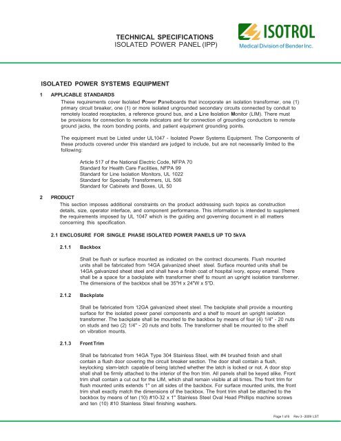
TECHNICAL SPECIFICATIONS<br />
ISOLATED POWER PANEL (IPP)<br />
Medical Division of <strong>Bender</strong> Inc.<br />
ISOLATED POWER SYSTEMS EQUIPMENT<br />
1 APPLICABLE STANDARDS<br />
These requirements cover Isolated Power Panelboards that incorporate an isolation transformer, one (1)<br />
primary circuit breaker, one (1) or more <strong>isolated</strong> ungrounded secondary circuits connected by conduit to<br />
remotely located receptacles, a reference ground bus, and a Line Isolation Monitor (LIM). There must<br />
be provisions for connection to remote indicators and for connection of grounding conductors to remote<br />
ground jacks, the room bonding points, and patient equipment grounding points.<br />
The equipment must be Listed under UL1047 - Isolated Power Systems Equipment. The Components of<br />
these products covered under this standard are judged to include, but are not necessarily limited to the<br />
following:<br />
Article 517 of the National Electric Code, NFPA 70<br />
Standard for Health Care Facilities, NFPA 99<br />
Standard for Line Isolation Monitors, UL 1022<br />
Standard for Specialty Transformers, UL 506<br />
Standard for Cabinets and Boxes, UL 50<br />
2 PRODUCT<br />
This section imposes additional constraints on the product addressing such topics as construction<br />
details, size, operator interface, and component performance. This information is intended to supplement<br />
the requirements imposed by UL 1047 which is the guiding and governing document in all matters<br />
concerning this specification.<br />
2.1 ENCLOSURE FOR SINGLE PHASE ISOLATED POWER PANELS UP TO 5kVA<br />
2.1.1 Backbox<br />
Shall be flush or surface mounted as indicated on the contract documents. Flush mounted<br />
units shall be fabricated from 14GA galvanized sheet steel. Surface mounted units shall be<br />
14GA galvanized sheet steel and shall have a finish coat of hospital ivory, epoxy enamel. There<br />
shall be a space for a backplate with transformer shelf to mount an upright isolation transformer.<br />
The dimensions of the backbox shall be 35"H x 24"W x 5"D.<br />
2.1.2 Backplate<br />
Shall be fabricated from 12GA galvanized sheet steel. The backplate shall provide a mounting<br />
surface for the <strong>isolated</strong> <strong>power</strong> <strong>panel</strong> components and a shelf to mount an upright isolation<br />
transformer. The backplate shall be mounted to the backbox by means of four (4) 1/4" - 20 nuts<br />
on studs and two (2) 1/4" - 20 nuts and bolts. The transformer shall be mounted to the shelf<br />
on vibration mounts.<br />
2.1.3 Front Trim<br />
Shall be fabricated from 14GA Type 304 Stainless Steel, with #4 brushed finish and shall<br />
contain a flush door covering the circuit breaker section. The door shall contain a flush,<br />
keylocking slam-latch capable of being latched whether the latch is locked or not. A door stop<br />
shall shall be firmly attached to the interior of the fron trim. All <strong>panel</strong>s shall be keyed alike. Front<br />
trim shall contain a cut out for the LIM, which shall remain visible at all times. The front trim for<br />
flush mounted units extends 1" on all sides of the backbox. For surface mounted units, the front<br />
trim shall exactly match the dimensions of the backbox. The front trim shall be attached to the<br />
backbox by means of ten (10) #10-32 x 1" Stainless Steel Oval Head Phillips machine screws<br />
and ten (10) #10 Stainless Steel finishing washers.<br />
Page 1 of 6<br />
Rev 3 - 2009 LST
TECHNICAL SPECIFICATIONS<br />
ISOLATED POWER PANEL (IPP)<br />
Medical Division of <strong>Bender</strong> Inc.<br />
ISOLATED POWER SYSTEMS EQUIPMENT (Continued)<br />
2.2 ENCLOSURE FOR SINGLE PHASE ISOLATED POWER PANELS UP TO 10kVA<br />
2.2.1 Backbox<br />
Shall be flush or surface mounted as indicated on the contract documents. Flush mounted units<br />
shall be fabricated from 14GA galvanized sheet steel. Surface mounted units shall be 14 GA<br />
galvanized sheet steel and shall have a finish coat of hospital ivory, epoxy enamel. There shall be<br />
a space for a backplate and a transformer shelf to mount an upright isolation transformer.<br />
The dimensions of the backbox shall be 41"H x 24"W x 8"D.<br />
2.2.2 Backplate<br />
Shall be fabricated from 12GA galvanized sheet steel. The backplate shall provide a mounting<br />
surface for all <strong>isolated</strong> <strong>power</strong> <strong>panel</strong> components except for the isolation transformer.<br />
The backplate shall be mounted to the backbox by means of four (4) 1/4" - 20 nuts on studs.<br />
2.2.3 Transformer Shelf<br />
Shall be fabricated 12GA galvanized sheet steel and securely mounted to the backbox by means<br />
of four (4) 1/4" - 20 nuts and bolts. The isolation transformer shall be mounted on vibration mounts.<br />
2.2.4 Front Trim (see Section 2.1.3)<br />
2.3 ENCLOSURE FOR SINGLE OR THREE PHASE ISOLATED POWER PANELS UP TO 15kVA<br />
2.3.1 Backbox<br />
Shall be flush or surface mounted as indicated on the contract documents. Flush mounted units shall<br />
be fabricated from 14GA galvanized sheet steel. Surface mounted units shall be 14GA galvanized<br />
sheet steel and shall have a finish coat of hospital ivory, epoxy enamel. There shall be a space for<br />
a backplate and a transformer shelf to mount an upright isolation transformer. The dimensions of<br />
the backbox shall be 48"H x 30"W x 12"D.<br />
2.3.2 Backplate<br />
Shall be fabricated from 12GA galvanized sheet steel. The backplate shall provide a mounting surface<br />
for all <strong>isolated</strong> <strong>power</strong> <strong>panel</strong> components except for the isolation transformer.<br />
The backplate shall be mounted to the backbox by means of four (4) 3/8“ – 16 bolts.<br />
2.3.3 Transformer Shelf<br />
Shall be fabricated 12GA galvanized sheet steel and securely mounted to the back box by means<br />
of four (4) 1/4" - 20 nuts and bolts. The isolation transformer shall be mounted on vibration mounts.<br />
2.3.4 Front Trim (see Section 2.1.3)<br />
2.4 ENCLOSURE FOR SINGLE OR THREE PHASE ISOLATED POWER PANELS UP TO 25kVA<br />
2.4.1 Backbox<br />
Shall be flush or surface mounted as indicated on the contract documents. Flush mounted units shall<br />
be fabricated from 14GA galvanized sheet steel. Surface mounted units shall be 14GA galvanized<br />
sheet steel and shall have a finish coat of hospital ivory, epoxy enamel. There shall be a space for<br />
a backplate and a transformer shelf to mount an upright isolation transformer. The dimensions of<br />
the backbox shall be 48"H x 30"W x 14"D.<br />
Page 2 of 6<br />
Rev 3 - 2009 LST
TECHNICAL SPECIFICATIONS<br />
ISOLATED POWER PANEL (IPP)<br />
Medical Division of <strong>Bender</strong> Inc.<br />
ISOLATED POWER SYSTEMS EQUIPMENT (Continued)<br />
2.4.2 Backplate<br />
Shall be fabricated from 12GA galvanized sheet steel. The backplate shall provide a mounting<br />
surface for all <strong>isolated</strong> <strong>power</strong> <strong>panel</strong> components except for the isolation transformer.<br />
The backplate shall be mounted to the backbox by means of four (4) 3/8“ - 16 bolts.<br />
2.4.3 Transformer Shelf<br />
Shall be fabricated 12GA galvanized sheet steel and securely mounted to the back box by means<br />
of four (4) 1/4" - 20 nuts and bolts. The isolation transformer shall be mounted on vibration mounts.<br />
2.4.4 Front Trim (see Section 2.1.3)<br />
2.5 COMPONENTS<br />
2.5.1 Isolation Transformer<br />
2.5.1.1 Single or three phase, 50 or 60Hz with primary and secondary voltages as indicated on<br />
the contract drawings.<br />
2.5.1.2 Class H rated insulation.<br />
2.5.1.3 Electrostatic shield between primary and secondary windings grounded to<br />
enclosure.<br />
2.5.1.4 Electrostatic shield designed so that it will prevent direct shorting of primary winding<br />
to secondary winding, and will reduce the coupling of harmonic distortions between<br />
the primary and secondary circuits.<br />
2.5.1.5 Core is of stacked design, securely clamped.<br />
2.5.1.6 Core and coil vacuum impregnated with final wrap of insulating material.<br />
2.5.1.7 Core and coils <strong>isolated</strong> from enclosure by means of a vibration dampening system.<br />
2.5.1.8 Total leakage current to ground from transformer secondary winding in compliance<br />
withUL1047, Tables 30.1 and 30.2.<br />
2.5.1.9 Maximum sound level of transformer: 25dB for 5kVA units or less, 30dB for 7.5kVA units,<br />
35dB for 10 & 15kVA units, and 40dB for 20 & 25 KVA units.<br />
2.5.1.10 Temperature rise limited to 115 degree C above ambient under full load conditions.<br />
2.5.1.11 Transformer UL listed or recognized as a component for the voltages, amperages, and<br />
kVA ratings required.<br />
2.5.2 Line Isolation Monitor (LIM)<br />
2.5.2.1 Solid state modular assembly of printed circuit boards utilizing SMD technology.<br />
2.5.2.2 Continuous monitoring of the impedance of each phase to ground.<br />
2.5.2.3 Must be capable of detecting all combinations of capacitive, resistive, balanced,<br />
unbalanced and hybrid faults.<br />
2.5.2.4 Total Hazard Current (THC) set at the factory to either 2mA or 5mA and shall be field<br />
adjustable to either milliampere.<br />
2.5.2.5 Combined analog and digital display of THC.<br />
2.5.2.6 Audible alarm which sounds in the event of a hazardous condition.<br />
2.5.2.7 Indicating LEDs to visually indicate the status of the system. Green to indicate<br />
“SAFE”, red to indicate“HAZARD” and amber to indicate that the audible alarm is in<br />
the "MUTE" mode. All LEDs and buttons shall be flush with the face of the LIM.<br />
2.5.2.8 A “TEST” button on the LIM face shall be activated to test all LIM functions. It shall<br />
not be possible to leave the button in the “TEST” position.<br />
2.5.2.9 The LIM shall perform an automatic self-calibration and self-check every twelve<br />
hours. An error code display shall alert the staff of an anomaly in the LIM / System<br />
operation.<br />
Page 3 of 6<br />
Rev 3 - 2009 LST
TECHNICAL SPECIFICATIONS<br />
ISOLATED POWER PANEL (IPP)<br />
Medical Division of <strong>Bender</strong> Inc.<br />
ISOLATED POWER SYSTEMS EQUIPMENT (Continued)<br />
2.5.2.10 Shall contain overload protection with an automatic reset feature.<br />
2.5.2.11 It shall be possible to order the LIM with an optional RS485 communication port<br />
and load monitoring.<br />
2.5.2.12 Field terminals shall be available for wiring remote LIM indicators with or without a<br />
display of THC.<br />
2.5.2.13 Shall be UL Recognized as a component.<br />
2.5.2.14 Shall have an easy to clean rugged Lexon front foil.<br />
2.5.2.15 The LIM shall be BENDER Model LIM2000 or equivalent.<br />
2.5.3 Primary Circuit Breaker<br />
2.5.3.1 Two-pole or three-pole sized in accordance with NFPA 70-1996 (N.E.C.) and UL 1047<br />
Standard and selected based on the transformer primary voltage as shown on the<br />
contract documents.<br />
2.5.3.2 Full size, thermal magnetic type, with minimum 10,000 AIC.<br />
2.5.4 Secondary Branch Circuit Breakers<br />
2.5.4.1 Two-pole or three-pole, ampacities, and quantities based on the contract documents.<br />
Sized in accordance with NFPA 70 (N.E.C.) and UL 1047 Standard.<br />
2.5.4.2 Full size, thermal magnetic type with minimum 10,000 AIC.<br />
2.5.5 Reference Ground Bus<br />
Shall contain a minimum of one (1) #4-2/0 main lug and nineteen (19) #14-4 grounding lugs.<br />
3 REMOTE INDICATORS for LINE ISOLATION MONITORS (OPTIONAL)<br />
Provide, where shown on the contract drawings, a single or multiple gang remote indicator which<br />
duplicates the audible and visual alarm indications of the LIM installed in the Isolated Power Panel. The<br />
remote indicator shall contain a green “SAFE” LED, a red “HAZARD” LED and a “MUTE” button with<br />
integral amber LED. The remote indicator shall function as follows:<br />
♦ The green LED stays illuminated when the leakage current is within predetermined limits.<br />
♦ The green LED extinguishes and the red LED illuminates when the predetermined limit is<br />
exceeded; an audible alarm also sounds.<br />
♦ When depressed, the “MUTE” button shall mute the audible alarm signal. Actuation of this button<br />
shall cause the integral amber LED to illuminate, indicating that the audible alarm has been<br />
silenced.<br />
♦ When the leakage current has returned to the acceptable limit level, the alarm indicators shall<br />
automatically reset.<br />
♦ Optional THC meter or digital display.<br />
Page 4 of 6<br />
Rev 3 - 2009 LST
TECHNICAL SPECIFICATIONS<br />
ISOLATED POWER PANEL (IPP)<br />
Medical Division of <strong>Bender</strong> Inc.<br />
ISOLATED POWER SYSTEMS EQUIPMENT (Continued)<br />
4 INSTALLATION<br />
Type XHHW wire with crosslinked polyethylene insulation and a dielectric constant of 3.5 or less shall be<br />
used.<br />
As necessary, special instructions shall be provided for field assembly, mounting and wiring of the<br />
equipment. They shall be part of a documentation package which includes three (3) sets of Operation and<br />
Maintenance manuals. These manuals shall include written instructions on the care and maintenance of<br />
the system, spare parts lists and certified “as built” drawings for the material furnished to the facility.<br />
Included will be an electrical schematic, an interconnection diagram, an overall outline dimensional<br />
drawing, and a LIM User Manual.<br />
5 TESTING & CERTIFICATION<br />
An engineer or senior technician shall be provided by the manufacturer for final testing and acceptance of<br />
the Isolated Power System. The following tasks shall be performed:<br />
♦ Simulate faults using the BENDER Type LT2000 Isolated Power Systems Test Kit, or equivalent.<br />
Repeat this test at each receptacle to ascertain that the LIM and associated branch circuit are<br />
functioning properly.<br />
♦ Check the calibration of the LIM meter using the LT2000 Isolated Power Systems Test Kit, or<br />
equivalent, and record the readings. Record the date and data in a permanent log book.<br />
♦ Certify that the system is properly installed and in correct working order.<br />
6 TRAINING<br />
As required, training shall be provided for the hospital maintenance and medical staff covering the correct<br />
operation and routine testing of the Isolated Power System. The function of the LIM will be explained and<br />
its test function demonstrated. The hospital maintenance staff shall be instructed on the proper use of the<br />
test equipment. The proper method of recording and logging data shall be explained. Finally, a log book<br />
shall be furnished that contains the data logged by the factory engineer / technician during the initial<br />
testing phase.<br />
7 ACCEPTABLE MANUFACTURERS<br />
The equipment shall be provided by ISOTROL or other approved supplier. Other suppliers seeking approval<br />
shall submit proof of their ability to comply with the requirements set forth in this specification.<br />
8 APPROVAL SUBMITTALS<br />
As part of the approval process, potential suppliers shall submit pertinent descriptive catalog literature.<br />
The following shop drawings shall also be submitted: a) Dimensional data, b) Transformer data, c) Line<br />
Isolation Monitor (LIM) details and performance data, d) Product <strong>specifications</strong> from the manufacturer, and<br />
e) Load center construction details including method of mounting, type of circuit breaker, current capacity,<br />
etc.<br />
9 ADDRESS OF MANUFACTURER<br />
BENDER / ISOTROL<br />
From USA, Canada and Mexico:<br />
Medical Division of <strong>Bender</strong> Inc. Phone: 800-833-6834<br />
700 Fox Chase<br />
Coatesville, PA 19320 USA<br />
All other countries:<br />
Phone: 610-383-9655<br />
Fax: 610-383-7100<br />
Page 5 of 6<br />
Rev 3 - 2009 LST
TECHNICAL SPECIFICATIONS<br />
ISOLATED POWER PANEL (IPP)<br />
Medical Division of <strong>Bender</strong> Inc.<br />
Notes:<br />
Page 6 of 6<br />
Rev 3 - 2009 LST


