MCO-19AIC MCO-19AICUV MCO-19AICUVH Series - Panasonic ...
MCO-19AIC MCO-19AICUV MCO-19AICUVH Series - Panasonic ...
MCO-19AIC MCO-19AICUV MCO-19AICUVH Series - Panasonic ...

You also want an ePaper? Increase the reach of your titles
YUMPU automatically turns print PDFs into web optimized ePapers that Google loves.
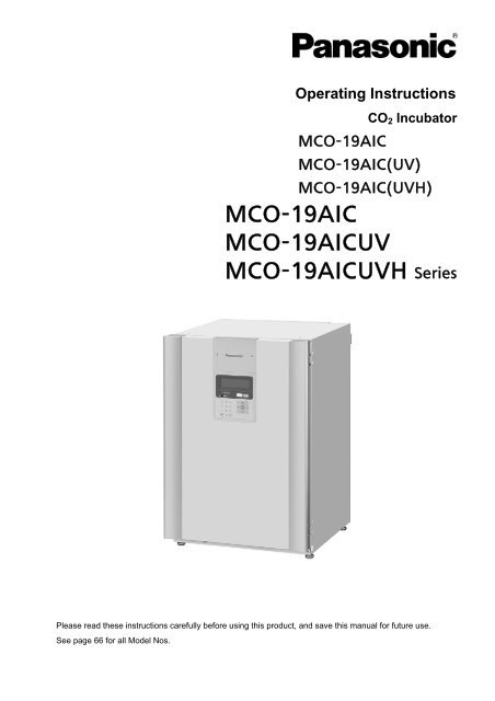
Operating Instructions<br />
<br />
<br />
<br />
CO 2 Incubator<br />
<br />
<br />
<br />
Please read these instructions carefully before using this product, and save this manual for future use.<br />
See page 66 for all Model Nos.
CONTENTS<br />
INTRODUCTION P. 2<br />
PRECAUTIONS FOR SAFE OPERATION P. 3<br />
LABELS ON INCUBATORS P. 7<br />
ENVIRONMENTAL CONDITIONS P. 7<br />
INCUBATOR COMPONENTS P. 8<br />
Control panel and keypad P. 10<br />
Remote alarm terminal P. 11<br />
INSTALLATION SITE P. 12<br />
INSTALLATION P. 13<br />
Connecting a CO 2 gas cylinder P. 14<br />
PREVENTING CONTAMINATION P. 15<br />
PRECAUTIONS FOR CULTURES P. 16<br />
Using unlock key P. 16<br />
INITIAL CLEANING METHOD P. 17<br />
REMOVING INNER ATTACHMENTS P. 18<br />
INSTALLING INNER ATTACHMENTS P. 20<br />
FILLING HUMIDIFYING PAN P. 21<br />
WATER LEVEL SENSOR P. 22<br />
ROUTINE MAINTENANCE P. 23<br />
CORRECT OPERATION P. 23<br />
LCD PANEL P. 24<br />
BASIC OPERATIONS ON CONTROL PANEL P. 25<br />
BASIC PARAMETERS<br />
Setting chamber temperature and CO 2 density P. 26<br />
Setting key lock P. 27<br />
Removing key lock P. 27<br />
Setting key lock password P. 28<br />
Setting high limit alarm temperature P. 30<br />
ALARM PARAMETERS P. 31<br />
UV LAMP PARAMETERS<br />
Using UV lamp P. 32<br />
Precautions when using UV lamp P. 33<br />
Setting UV lamp ON period P. 34<br />
Lighting UV lamp for 24 hours P. 35<br />
OTHER PARAMETERS<br />
Setting date, time, and log interval P. 36<br />
Initial settings (LCD/DAQ parameters) P. 38<br />
DISPLAYING THE LOG P. 39<br />
Transferring data P. 40<br />
H 2 O 2 DECONTAMINATION P. 41<br />
Precautions when handling H 2 O 2 reagent P. 45<br />
ALARMS, SAFETY, AND SELF-DIAGNOSIS P. 46<br />
CALIBRATION<br />
Temperature/CO 2 calibration P. 49<br />
TROUBLESHOOTING P. 51<br />
DISPOSAL OF UNIT P. 53<br />
AUTOMATIC CO 2 CYLINDER CHANGEOVER P. 58<br />
AUTOMATIC CO 2 DENSITY CALIBRATION P. 60<br />
STACKING INCUBATORS P. 63<br />
SPECIFICATIONS P. 65<br />
PERFORMANCE P. 66<br />
SAFETY CHECK SHEET P. 67<br />
1
INTRODUCTION<br />
■ Read this operating instruction carefully before using the Product and follow the instructions for safety<br />
operation.<br />
■ Our company disavows any responsibility for safety if the Product is used for other than the intended<br />
use or used with any procedures other than those given in this operating instruction.<br />
■ Keep this operating instruction in a suitable place so that it can be referred to as necessary.<br />
■ The contents of this operating instruction are subject to change without notice for improvement of<br />
performance or functions.<br />
■ Contact our sales representative or agent if any page of the operating instruction is lost or the page<br />
order is incorrect.<br />
■ Contact our sales representative or agent if any point in this operating instruction is unclear or if there<br />
are any inaccuracies.<br />
■ No part of this operating instruction may be reproduced in any form without the expressed written<br />
permission of our company.<br />
CAUTION<br />
Our company guarantees the product under certain warranty conditions. Our company in no<br />
way shall be responsible for any loss of content or damage of content.<br />
Microsoft, Windows, Windows 7, Windows Vista, Windows XP and Windows 2000 are registered<br />
trademarks in the United States of Microsoft Corporation and various other countries.<br />
2
PRECAUTIONS FOR SAFE OPERATION<br />
It is imperative that the user complies with this operating instruction<br />
as it contains important safety advice.<br />
Items and procedures are described so that you can use this unit correctly and safely.<br />
If the precautions advised are followed, this will prevent possible injury to the user and<br />
any other person.<br />
Precautions are illustrated in the following way:<br />
WARNING<br />
Failure to observe WARNING signs could result in a hazard to personnel<br />
possibly resulting in serious injury or death.<br />
CAUTION<br />
Failure to observe CAUTION signs could result in injury to personnel and<br />
damage to the unit and associated property.<br />
Symbol shows;<br />
this symbol means caution.<br />
this symbol means an action is prohibited.<br />
this symbol means an instruction must be followed.<br />
Be sure to keep this operating instruction in a place accessible to users of this unit.<br />
< Label on the unit ><br />
This mark is labeled on the cover in which the electrical components of high voltage<br />
are enclosed to prevent the electric shock.<br />
The cover should be removed by a qualified engineer or a service personnel only.<br />
WARNING<br />
As with any equipment that uses CO 2 gas, there is a likelihood of oxygen depletion in the vicinity<br />
of the equipment. It is important that you assess the work site to ensure there is suitable and<br />
sufficient ventilation. If restricted ventilation is suspected, then other methods of ensuring a<br />
safe environment must be considered. These may include atmosphere monitoring and<br />
warning devices.<br />
3
PRECAUTIONS FOR SAFE OPERATION<br />
WARNING<br />
Do not use the unit outdoors. Current leakage or electric shock may result if the unit is exposed to<br />
rain water.<br />
Only qualified engineers or service personnel should install the unit. The installation by<br />
unqualified personnel may cause electric shock or fire.<br />
Install the unit on a sturdy floor and take an adequate precaution to prevent the unit from<br />
turning over. If the floor is not strong enough or the installation site is not adequate, this may result<br />
in injury from the unit falling or tipping over.<br />
Never install the unit in a humid place or a place where it is likely to be splashed by water.<br />
Deterioration of the insulation may result which could cause current leakage or electric shock.<br />
Never install the unit in a flammable or volatile location. This may cause explosion or fire.<br />
Never install the unit where acid or corrosive gases are present as current leakage or electric<br />
shock may result due to corrosion.<br />
Always ground (earth) the unit to prevent electric shock. If the power supply outlet is not<br />
grounded, it will be necessary to install a ground by qualified engineers.<br />
Never ground the unit through a gas pipe, water main, telephone line or lightning rod. Such<br />
grounding may cause electric shock in the case of an incomplete circuit.<br />
Connect the unit to a power source as indicated on the rating label attached to the unit. Use<br />
of any other voltage or frequency other than that on the rating label may cause fire or electric shock.<br />
Never store volatile or flammable substances in this unit if the container cannot be sealed. These<br />
may cause explosion or fire.<br />
Do not insert metal objects such as a pin or a wire into any vent, gap or any outlet on the unit.<br />
This may cause electric shock or injury by accidental contact with moving parts.<br />
Use this unit in safe area when treating the poison, harmful or radiate articles. Improper use<br />
may cause bad effect on your health or environment.<br />
Turn off the power switch (if provided) and disconnect the power supply to the unit prior to any<br />
repair or maintenance of the unit in order to prevent electric shock or injury.<br />
Do not touch any electrical parts (such as power supply plug) or operate switches with a wet<br />
hand. This may cause electric shock.<br />
4
WARNING<br />
Ensure you do not inhale or consume medication or aerosols from around the unit at the time of<br />
maintenance. These may be harmful to your health.<br />
Never splash water directly onto the unit as this may cause electric shock or short circuit.<br />
Never put containers with liquid on the unit as this may cause electric shock or short circuit when<br />
the liquid is spilled.<br />
Never bind, process, or step on the power supply cord, or never damage or break the power<br />
supply plug. A broken supply cord or plug may cause fire or electric shock.<br />
Do not use the supply cord if its plug is loose. Such supply cord may cause fire or electric shock.<br />
Never disassemble, repair, or modify the unit yourself. Any such work carried out by an<br />
unauthorized person may result in fire, or electric shock or injury due to a malfunction.<br />
Disconnect the power supply plug if there is something wrong with the unit. Continued<br />
abnormal operation may cause electric shock or fire.<br />
When removing the plug from the power supply outlet, grip the power supply plug, not the cord.<br />
Pulling the cord may result in electric shock or fire by short circuit.<br />
Disconnect the power supply plug before moving the unit. Take care not to damage the power<br />
cord. A damaged cord may cause electric shock or fire.<br />
Disconnect the power plug when the unit is not used for long periods. Keeping the connection<br />
may cause electric shock, current leakage, or fire due to the deterioration of insulation.<br />
If the unit is to be stored unused in an unsupervised area for an extended period, ensure that<br />
children do not have access and that doors cannot be closed completely.<br />
The disposal of the unit should be accomplished by appropriate personnel. Remove doors to<br />
prevent accidents such as suffocation.<br />
Do not put the packing plastic bag within reach of children as suffocation may result.<br />
Use the reagent specified by our company for H 2 O 2 decontamination. Using a different H 2 O 2<br />
solution may result in explosion or damage to the incubator.<br />
When performing H 2 O 2 decontamination, securely close the internal and external doors. Failure to<br />
do so may be harmful to health due to leakage of H 2 O 2 gas.<br />
During H 2 O 2 decontamination, plug the access hole with the silicon cap that is provided. Failure<br />
to do so may be harmful to health due to leakage of H 2 O 2 gas.<br />
5
PRECAUTIONS FOR SAFE OPERATION<br />
CAUTION<br />
This unit must be plugged into a dedicated circuit protected by branch circuit breaker.<br />
Use a dedicated power source as indicated on the rating label attached to the unit. A multiple-tap<br />
may cause fire resulting from abnormal heating.<br />
Never store corrosive substances such as acid or alkali in this unit if the container cannot be<br />
sealed. These may cause corrosion of inner components or electric parts.<br />
Check the setting when starting up of operation after power failure or turning off of power<br />
switch. The stored items may be damaged due to the change of setting.<br />
Be careful not to tip over the unit during movement to prevent damage or injury.<br />
Prepare a safety check sheet (copy the last page) when you request any repair or maintenance for<br />
the safety of service personnel.<br />
Wear rubber gloves when handling the H 2 O 2 reagent. Direct contact with the H 2 O 2 reagent may<br />
result in inflammation of the skin.<br />
H 2 O 2 decontamination can be performed only for the chamber and chamber attachments with<br />
standard specifications, and not for any other objects.<br />
Perform H 2 O 2 decontamination with the chamber attachments arranged as specified by our<br />
company. Arranging them in a different way may result in insufficient decontamination.<br />
After H 2 O 2 decontamination has been completed, wear rubber gloves and use a non-woven cloth<br />
to wipe off the residual H 2 O 2 fluid from the bottom of the chamber, any objects that were<br />
decontaminated, and the bottoms of ducts.<br />
6
LABELS ON INCUBATOR<br />
Warning and caution labels are attached to the incubator. The following table describes the labels.<br />
This label is attached to covers that access high-voltage electrical components to<br />
prevent electric shock. Only a qualified engineer or service personnel should be<br />
allowed to open these covers.<br />
This symbol indicates an ultraviolet light (UV) caution.<br />
This symbol indicates that caution is required. Refer to product documentation for<br />
details.<br />
This symbol indicates a hot surface.<br />
This symbol indicates an earth.<br />
This symbol means “ON” for a power switch.<br />
This symbol means “OFF” for a power switch.<br />
ENVIRONMENTAL CONDITIONS<br />
This equipment is designed to be safe at least under the following conditions (based on the IEC 61010-1):<br />
■ Indoor use;<br />
■ Altitude up to 2000 m;<br />
■ Ambient temperature 5 o C to 40 o C<br />
■ Maximum relative humidity 80 % for temperature up to 31 o C decreasing linearly to 50 % relative<br />
humidity at 40 o C;<br />
■ Mains supply voltage fluctuations not to exceed ±10 % of the nominal voltage;<br />
■ Other supply voltage fluctuations as stated by the manufacturer;<br />
■ Transient overvoltages according to Installation Categories (Overvoltage Categories) II; For mains<br />
supply the minimum and normal category is II;<br />
■ Pollution degree 2 in accordance with IEC 60664.<br />
7
INCUBATOR COMPONENTS<br />
Handles<br />
6 5 12 7 9 (inside) 8<br />
2<br />
1<br />
4<br />
15, 16 (inside)<br />
For <strong>MCO</strong>-<strong>19AIC</strong>(UVH)/<strong>19AIC</strong>(UV) or<br />
when <strong>MCO</strong>-19UVS is installed.<br />
Handles<br />
22<br />
10<br />
13 (inside)<br />
14<br />
3<br />
21<br />
18<br />
17<br />
20<br />
11<br />
19<br />
For <strong>MCO</strong>-<strong>19AIC</strong>(UVH)/<strong>19AIC</strong>(UV) or<br />
when <strong>MCO</strong>-19UVS is installed.<br />
Rear Right Side<br />
Rear Left Side<br />
8
1. Outer door: The outer door is held to the frame with the magnetic seal. The door heater is installed in<br />
the door panel. The door opening is reversible. Contact our sales representative or agent to change the<br />
door hinge from left to right or vice versa.<br />
2. Inner door: The inner door is made of tempered glass. However do not subject the glass to excessive<br />
impacts.<br />
3. Leveling feet: The leveling feet can be turned to adjust the height. Adjust the feet so that the incubator<br />
is level.<br />
4. Trays: The trays can be pulled out toward you.<br />
5. Tray supports: The tray supports can be removed by lifting the front side and pulling toward you.<br />
6. Side supports: The right and left side supports can be removed for disinfection. Refer to page 19 and<br />
23.<br />
7. Fan cover: The fan cover serves as the inlet for circulating air. It is removable.<br />
8. Duct: The duct for the path for circulating air. It is removable.<br />
9. Fan (inside the duct): The fan is made from polypropylene resin. It can be disinfected in an autoclave.<br />
10. Sample air outlet: The sample air outlet also functions as an internal gas outlet. Normally, cover this<br />
outlet with the sample air outlet cap.<br />
11. Connecting port A/B for CO 2 gas pipe: When the optional <strong>MCO</strong>-21GC gas auto changer is installed,<br />
both ports A and B are available. If the <strong>MCO</strong>-21GC is not installed, only port A is available. Refer to page<br />
14 for gas cylinder connection. Ensure that the gas pressure is set at 0.03 MPa(G) (0.3 kgf/cm 2 (G), 4.3<br />
psi(G)). Refer to page 58 for gas auto changer.<br />
12. Door switch: Detects the door opening/closing and stops the fan and electromagnetic valve for CO 2<br />
when the door is open. The UV lamp* is also deactivated by the door opening*.<br />
13. Humidifying pan: Fill the humidifying pan with sterile distilled water. Install the humidifying pan<br />
properly so that it can be covered with the humidifying pan cover.<br />
14. Humidifying pan cover: The cover prevents the UV light entering the chamber. When filling the<br />
humidifying pan, lift the front side and take out the humidifying pan. Refer to page 21 for details.<br />
15. UV lamp*: This UV lamp does not generate ozone. Never look directly at the UV light. For<br />
replacement, contact our sales representative or agent.<br />
16. Water level sensor: This sensor detects the water level in the humidifying pan. Refer to page 22 for<br />
details.<br />
17. Remote alarm terminals: Refer to page 11.<br />
18. Access port: Place the silicon caps on the port both outside and inside when the port is not being<br />
used.<br />
19. Power switch: This is the main switch for the incubator. It also functions as an overcurrent breaker.<br />
20. Glow starter*: The glow is started if for the UV lamp.<br />
21. Attachment location for electric key: This is the attachment location for the electric key included in<br />
the optional component H 2 O 2 decon set (<strong>MCO</strong>-HL). This kit must be attached to perform H 2 O 2<br />
decontamination. Refer to the installation procedure for <strong>MCO</strong>-HL for details.<br />
22. Sample air outlet cap: Always attach this cap except when using the sample air outlet.<br />
* <strong>MCO</strong>-<strong>19AIC</strong>(UVH)/<strong>19AIC</strong>(UV) or when an optional UV system set (<strong>MCO</strong>-19UVS) is installed.<br />
9
INCUBATOR COMPONENTS<br />
Control panel and keypad<br />
1<br />
3<br />
2<br />
5<br />
10<br />
11<br />
4<br />
8<br />
9<br />
6 7<br />
1. LCD panel<br />
2. High limit regulator:<br />
This regulator is used to set the high<br />
temperature limit.<br />
3. Overheat indicator (OVER HEAT):<br />
This indicator lights when the chamber<br />
temperature reaches the high limit.<br />
4. Menu key (MENU):<br />
Press this key to access the menu.<br />
7. CE Key (CE):<br />
Press this key to clear the entered value<br />
when entering a setting.<br />
8. Cursor Keys (Up, Down, Left, and Right):<br />
Use these keys to move the cursor on the<br />
LCD panel.<br />
9. Enter key (ENT):<br />
Press this key to select a menu command.<br />
When entering a setting, pressing this key to<br />
move to the next parameter.<br />
5. Contrast knob (CONT.):<br />
Turn this knob to adjust the contrast of the<br />
LCD.<br />
6. Buzzer key (BUZZER):<br />
Press this key to silence the buzzer.<br />
Note: It is not possible to silence the buzzer<br />
for the high limit temperature alarm.<br />
10. Numeric Keys<br />
11. H 2 O 2 Key (H2O2):<br />
Press this key to start the H 2 O 2<br />
decontamination. Refer to page 41-44 for<br />
details.<br />
※ The following optional accessories must be installed to perform decontamination.<br />
・UV system set (<strong>MCO</strong>-19UVS)<br />
(This is provided as standard equipment for the <strong>MCO</strong>-<strong>19AIC</strong>(UVH)/<strong>19AIC</strong>(UV).)<br />
・H 2 O 2 decon set (<strong>MCO</strong>-HL)<br />
・H 2 O 2 generator (<strong>MCO</strong>-HP)<br />
10
Remote alarm terminal<br />
The remote alarm terminal is located at the rear right side of the incubator.<br />
Remote alarm<br />
terminals<br />
The alarm is outputted from this terminal. Contact capacity is DC 30 V, 2 A.<br />
Normal:<br />
Open<br />
Alarm:<br />
Closed<br />
Note:<br />
• When the power switch is OFF or power is interrupted, the contact output will be closed.<br />
• The remote alarm cannot be silenced by pressing the buzzer key (BUZZER) since the remote alarm is<br />
not conjunct with the buzzer key (BUZZER).<br />
REMOTE ALARM<br />
MAX DC30V 2A<br />
Remote alarm terminal<br />
N.O.<br />
11
INSTALLATION SITE<br />
For correct operation of the incubator, install it in a location with the following conditions.<br />
WARNING<br />
When using CO 2 gas for control, make sure that there is adequate ventilation. Using CO 2 gas in a<br />
small room without adequate ventilation may cause gas poisoning or oxygen deprivation. In addition,<br />
when opening the incubator doors, do not directly inhale the air in the chamber.<br />
Si l’appareil est utilisé dans un evdroit restreint, le niveau de la densite CO 2 de l’air peut s’élever et peut<br />
être nocif aux humains. Evitez d’aspirer l’air provenant de l’inérieur de l’appareil quand vous ouverz la<br />
porte.<br />
• Normal air environment<br />
Install the incubator in an environment with normal air.<br />
• Do not expose to direct sunlight<br />
Do not install the incubator in a location where it will be exposed to direct sunlight. If the incubator is<br />
operated in direct sunlight, performance will be adversely affected.<br />
• Separate from heat sources<br />
Do not install the incubator near significant heat sources, such as heaters, boilers, ovens, or autoclaves.<br />
Heat will adversely affect the performance of the incubator.<br />
• Ambient temperature at least 5 C lower than set temperature<br />
The control temperature of the incubator is at least 5 C higher than the ambient temperature. For<br />
example, if the chamber is controlled at 37 C, the ambient temperature must normally be no more than<br />
32 C. Do not allow the ambient temperature to become too high.<br />
• Strong and level floor<br />
Select a site with a strong and level floor. If the floor is uneven or the installation is not level, the incubator<br />
will be unstable and this may cause accident or injury. To avoid vibration and noise, always make sure<br />
that the installation is stable. An unstable surface may result in vibration or noise.<br />
WARNING<br />
Install the incubator at a location that can support the weight. If the floor is not strong enough or if the<br />
installation is insufficient, the incubator may fall over and cause injury.<br />
Always make sure that the floor is strong, even, and level, and that the incubator will not tip over.<br />
An insufficient installation may result in injury due to water leakage or the incubator falling over.<br />
• Low humidity<br />
Select a site with a relative humidity of 80 %R.H. or lower. Using the incubator in high humidity may result<br />
in current leakage or electric shock.<br />
WARNING<br />
Do not use the incubator outdoors. If the incubator is exposed to rain water, it may result in current<br />
leakage or electric shock.<br />
Never install the incubator in a moist location, such as near a sink or water line, or where it is<br />
likely to be exposed to water. In addition, do not install it near water or steam pipes. Moisture can<br />
cause the insulation to deteriorate, which may result in current leakage or electric shock.<br />
• No inflammable or corrosive gas<br />
Never install the incubator in a location where it will be exposed to inflammable or corrosive gas. Doing so<br />
may result in explosion or fire. In addition, insulation may deteriorate due to corrosion of protective casing,<br />
resulting in current leakage or electric shock.<br />
• No falling objects<br />
Do not install the incubator in a location where there is the possibility of objects falling from above. Doing<br />
so may result in damage or accident.<br />
12
INSTALLATION<br />
1. Remove the packing tape and clean up.<br />
Remove all the tape that is securing the doors and the inner attachments. Open the doors for ventilation.<br />
If the outer panels are dirty, dampen a cloth with a diluted neutral detergent and wipe them. (Using an<br />
undiluted solution may damage the plastic. Follow the diluting instructions for the detergent that is used.)<br />
Wipe off the residual detergent with a wet cloth and then wipe off any moisture.<br />
Note:<br />
Remove the cable tie banding the power supply cord. Prolonged banding may cause the corrosion of<br />
the cord coating.<br />
WARNING<br />
Do not leave the plastic wrapping bags within reach of children. If the bag is placed over a child’s<br />
head, it can block the mouth and nose and cause suffocation.<br />
2. Adjust the leveling feet.<br />
Adjust the leveling feet by turning them counterclockwise to level<br />
the incubator. (See the illustration on the right.)<br />
3. Ground the incubator.<br />
Ground the incubator during installation to prevent electric shock<br />
in case the insulation is not sufficient. If there is no ground wire at<br />
the location, consult with qualified service personnel.<br />
• When a ground must be installed<br />
If a grounded 3-pole outlet is not available, then a ground must<br />
be installed. Consult with qualified service personnel.<br />
Leveling feet<br />
WARNING<br />
To prevent electric shock, always ground the incubator. If grounding is not possible, then have a ground<br />
installed by qualified personnel. If the incubator is not grounded, it may result in electric shock.<br />
Never connect the ground wire to a gas pipe, water pipe, lightning rod, or telephone ground wire.<br />
Doing so may cause electric shock.<br />
• Installing a ground fault circuit breaker<br />
If using the incubator in the location with moisture or humidity cannot be avoided, then it is recommended<br />
that a ground fault circuit breaker be installed in the power supply circuit (i.e., the power supply at the<br />
incubator). Have the circuit breaker installed by qualified service personnel.<br />
CAUTION<br />
Do not climb on the incubator or place objects on top of it. Doing so may damage it or cause it to fall<br />
over, resulting in injury. If it is to be stacked, refer to page 63 and stack it securely.<br />
• When the incubator is not in use<br />
Empty the water from the humidifying pan and remove moisture from the chamber. Make sure that the<br />
chamber is completely dry before closing the doors. Failure to do so may result in damage.<br />
• Before moving the incubator<br />
Before moving the incubator, empty the water from the humidifying pan, disconnect the power supply plug<br />
from the outlet, and make sure that the cord will not be damaged. Failure to do so may result in electric<br />
shock or fire.<br />
13
INSTALLATION<br />
Connecting a CO 2 gas cylinder<br />
WARNING<br />
When connecting a gas cylinder to the incubator, confirm the gas type. Confirm that the connections<br />
are secure and that no gas will escape. Be sure to use the specified pressure. Using an incorrect<br />
gas or pressure may result in explosion or fire, or in gas poisoning or oxygen deprivation due to escaping<br />
gas.<br />
Install the incubator in a location with adequate ventilation. If adequate ventilation cannot be<br />
provided, then install an alarm system using CO 2 and O 2 densitometers.<br />
1. Use a liquefied CO 2 gas cylinder (at least 99.5 % pure). The siphon (dip tube) type cannot be used.<br />
2. Install a gas regulator rated at 25 MPa(G) (250 kgf/cm 2 (G), 3600 psi(G)) for the primary side, and 0.2<br />
MPa(G) (2 kgf/cm 2 (G), 30 psi(G)) for the secondary side.<br />
3. Using the gas tube that is provided, connect the gas regulator to the connecting port A/B for CO 2 gas<br />
pipe at the rear left side of the incubator.<br />
Note:<br />
If the CO 2 gas is supplied to multiple CO 2 incubators from a single gas cylinder, a CO 2 solid will be<br />
formed in the gas regulator. The gas regulator safety valve will operate, and there may an explosive<br />
sound.<br />
When the <strong>MCO</strong>-21GC is not mounted<br />
Using the gas tube that is provided, connect the gas regulator for the CO 2 gas cylinder to connecting port<br />
A for CO 2 gas pipe located at the rear side of the incubator. After connecting the gas tube, make sure that<br />
no gas is leaking.<br />
When the <strong>MCO</strong>-21GC is mounted<br />
Connect a pair of CO 2 gas cylinders with gas regulators independently. The gas supply line will be<br />
switched automatically. Connect the main cylinder to the connecting port A for CO 2 gas pipe and the<br />
reserve cylinder to the connecting port B for CO 2 gas pipe. After connecting the cylinders, make sure that<br />
no gas is leaking.<br />
• For details on installing the optional automatic CO 2 cylinder changeover kit (<strong>MCO</strong>-21GC), refer to the<br />
<strong>MCO</strong>-21GC installation guide. For details on using the <strong>MCO</strong>-21GC, refer to page 58.<br />
4. Set the CO 2 gas on the secondary side to 0.03 MPa(G) (0.3 kgf/cm 2 (G), 4.3 psi(G)) for gas injection. As<br />
the pressure increases, the CO 2 gas density control range will increase. Excessive pressure may cause<br />
gas supply lines inside the incubator to come loose, which may result in gas poisoning or oxygen<br />
deprivation due to the escaping of gas. If gas lines come loose, the incubator must be repaired.<br />
• The gas lines connected to the incubator will degrade over time. If any deterioration or abnormalities<br />
are found during inspection, replace the lines immediately.<br />
14
PREVENTING CONTAMINATION<br />
To prevent contamination of the chamber, select a suitable installation site.<br />
• Avoid locations with high temperatures or humidity.<br />
Avoid locations with high temperatures or humidity, because of a greater presence of microorganisms in<br />
the air.<br />
• Avoid locations with passers-by or drafts.<br />
Avoid locations near doors, air conditioners, fans, etc., where passers-by or drafts can facilitate the entry<br />
of microorganisms into the chamber.<br />
• If possible, use a cleanroom.<br />
To achieve a better culture, it is recommended that a cleanroom be used if one is available.<br />
• Use clean containers.<br />
The greatest cause of contamination is dirty containers for cultures. Be careful not to get containers or<br />
trays dirty when taking them in and out.<br />
• Keep the chamber clean.<br />
Wipe off any fingerprints. If water spills from the humidifying pan, or if the doors are left open for a long<br />
time, condensation may form on the inside of the doors. If that occurs, wipe off the condensation with a<br />
dry sterile gauze. In particular, clean and disinfect the chamber if the culture medium is spilled. For details,<br />
refer to “ROUTINE MAINTENANCE” on page 23.<br />
• Use sterile distilled water in the humidifying pan.<br />
Always use sterile distilled water in the humidifying pan. Do not use ultrapure water, because it may<br />
cause red rust-like particles in the humidifying pan.<br />
The water level alarm is displayed in the status display area on the control panel. Quickly refill the water<br />
in the humidifying pan when the water level alarm is displayed. Adding low-temperature water will<br />
significantly lower the temperature in the chamber. Clean the humidifying pan once a month.<br />
• Keep the incubator out of direct airflows from air conditioners or fans.<br />
Cool airflow from an air conditioner may cause condensation and lead to possible contamination.<br />
15
PRECAUTIONS FOR CULTURES<br />
• Leave space between culture containers.<br />
Always leave space for ventilation between culture containers (Petri dishes, flasks, etc.). Inadequate<br />
spacing may result in uneven temperature distribution and CO 2 gas density.<br />
• Do not place harmful materials in the chamber.<br />
Never place samples that release acidic, alkali, or corrosive gas in the chamber. Doing so may cause<br />
damage resulting from discoloration or corrosion.<br />
• Close the inner door.<br />
Always close the inner door before closing the outer door. Failure to close the inner door will adversely<br />
affect performance even if the outer door is closed.<br />
• Open and close the doors gently.<br />
Always open and close the doors gently. Closing the doors forcefully may cause spillage of the culture<br />
medium, incomplete closing, or damage to the gasket. Before opening the inner door, check through the<br />
glass to confirm that the UV lamp is OFF (if the <strong>MCO</strong>-<strong>19AIC</strong>(UVH)/<strong>19AIC</strong>(UV) or the optional<br />
<strong>MCO</strong>-19UVS is installed).<br />
• Be careful when closing the outer door.<br />
Use the handle when closing the outer door. Holding the door in other places may cause injury by getting<br />
fingers caught in the door. Do not lean on the outer door. Doing so may result in injury from the outer door<br />
coming loose or the incubator falling over, or it may cause current leakage or electric shock.<br />
• Be careful of the inside of the outer door.<br />
The inside of the outer door may become hot.<br />
• Avoid using excessive force on the inner door.<br />
Do not put your hand on the glass, poke it with sharp objects, or apply strong force. Doing so may result<br />
in injury from breaking the glass.<br />
• Check the cause of any alarm buzzer.<br />
If an alarm buzzer sounds while the incubator is in use, immediately check the cause of the alarm. For<br />
details on what may cause an alarm buzzer to sound, refer to page 46.<br />
Using unlock key<br />
• Unlocking when power is interrupted<br />
If power is interrupted to the <strong>MCO</strong>-<strong>19AIC</strong>(UVH) or <strong>MCO</strong>-<strong>19AIC</strong>(UV)/<strong>19AIC</strong> with an <strong>MCO</strong>-HL installed, the<br />
outer door is electrically locked. To unlock the outer door while the power is interrupted, use the unlock<br />
key that is provided. To lock the outer door again, turn the unlock key to the lock direction while the outer<br />
door is open. After the outer door has been locked condition manually, then close the outer door.<br />
Note:<br />
The outer door cannot be locked by using the unlock key while the outer door is closed. Lock the outer<br />
door while it is open. Attempting to turn the unlock key while the outer door is closed may damage the<br />
electric lock system.<br />
WARNING<br />
For the <strong>MCO</strong>-<strong>19AIC</strong>(UVH) or <strong>MCO</strong>-<strong>19AIC</strong>(UV)/<strong>19AIC</strong> with an <strong>MCO</strong>-HL installed, the outer door is<br />
electrically locked during decontamination. The chamber is filled with H 2 O 2 gas during decontamination.<br />
Do not unlock the outer door during decontamination.<br />
16
INITIAL CLEANING METHOD<br />
Before using the incubator for the first time, clean dirt (tape residue, smear, etc.) from the<br />
chamber and the inner attachments thoroughly. To keep the chamber clean is essential to<br />
get the proper performance out of the incubator. Use the following steps to clean the<br />
incubator properly.<br />
1. Remove the inner attachments, referring to “REMOVING INNER ATTACHMENTS” on page 18.<br />
2. Clean the removed inner attachments, the chamber inside walls and the inner door gaskets with a cloth<br />
or sponge soaked in neutral detergent, diluted by 5 % or less. (Undiluted detergent can damage the<br />
plastic components. For the dilution, refer to the instruction of the detergent.) (Fig. 1)<br />
CAUTION<br />
Do not use detergents or antiseptic solutions with acid, alkali, or chlorine. Doing so may cause<br />
discoloration, corrosion, or rusting.<br />
Be careful to keep the diluted detergent or water out of the temperature sensor, the CO 2 gas injection port,<br />
the inner sample air access port, the fan motor shaft bearing, and the inner sample air outlet<br />
(Fig.2 ). Also, do not wash the temperature sensor, the water level sensor and the UV lamp using<br />
detergent. Doing so may cause failure. (Fig. 2)<br />
3. Soak a gauze or unwoven cloth in distilled water and wring it tightly, and then wipe off the residual<br />
detergent thoroughly.<br />
4. Wash the silicon caps (2 pcs) for the access port and the fan using the above mentioned detergent and<br />
rinse them with distilled water, and then autoclave them for sterilization (121 o C, 20 minutes).<br />
5. Wipe up the inside walls and the inner attachments like trays thoroughly with a cloth or unwoven cloth<br />
soaked in alcohol for disinfection. Be careful not to leave any residue alcohol.<br />
6. Reinstall the inner attachments correctly and securely, referring to “INSTALLING INNER<br />
ATTACHMENTS” on page 20.<br />
Silicon<br />
cap<br />
Temp. sensor<br />
(UV lamp)<br />
Water level sensor<br />
Fig. 1 Fig. 2<br />
17
REMOVING INNER ATTACHMENTS<br />
CAUTION<br />
Wear rubber gloves when performing maintenance on the chamber. Failure to wear gloves may<br />
result in cuts or abrasions from sharp edges or corners.<br />
Be careful not to damage the water level sensor or the UV lamp in the duct (if the<br />
<strong>MCO</strong>-<strong>19AIC</strong>(UVH)/<strong>19AIC</strong>(UV) or the optional <strong>MCO</strong>-19UVS is installed).<br />
Do not use detergents or antiseptic solutions with acid, alkali, or chlorine. Doing so may cause<br />
discoloration, corrosion, or rusting.<br />
1. Turn OFF the power to the incubator.<br />
2. Open the outer and inner doors and pull out all the trays. (Fig. 1)<br />
3. Lift the front of the tray supports and pull them out. (Fig. 2)<br />
4. Lift the humidifying pan cover off from the pins on the rear side. (Fig. 3)<br />
5. Pull out the humidifying pan. (Fig. 4)<br />
6. Loosen the two screws securing the fan cover and take off the fan cover. (Fig. 5)<br />
7. Lift the duct and remove it from the pins on the rear side. (Fig. 6)<br />
Pins<br />
Tray support<br />
Humidifying pan cover<br />
Fig. 1 Fig. 2 Fig. 3<br />
Duct<br />
Fan cover<br />
Humidifying pan<br />
Fig. 4 Fig. 5 Fig. 6<br />
18
8. Remove the fan by pulling out the central spring and then by pulling out the fan. (Fig. 7)<br />
9. Remove the screw securing the clamp for the side support. (Fig. 8)<br />
10. Remove the clamp. (Fig. 9)<br />
11. Lift the side supports off of the pins. (Fig. 10)<br />
12. Remove the silicon caps of the access port, one each from interior (Fig. 11) and exterior (Fig. 12).<br />
1Pull out the central spring<br />
Screw<br />
Clamp<br />
2Pull out the fan<br />
Fig. 7 Fig. 8 Fig. 9<br />
Silicon cap<br />
Silicon cap<br />
Side<br />
support<br />
Fig. 10 Fig. 11 Fig. 12<br />
19
INSTALLING INNER ATTACHMENTS<br />
Use the following steps to install the inner attachments properly.<br />
1. To reinstall all the attachments, perform the procedure in reverse order from step 12 on page 19.<br />
2. When installing the fan, insert it to the motor shaft securely. Lightly turn the fan manually to make sure<br />
that it does not touch the rear panel. Then install the central spring. (Fig. 1)<br />
CAUTION<br />
If the fan is not inserted deep enough, the intended velocity performance cannot be achieved, which may<br />
cause culture failure or insufficient decontamination.<br />
3. To install the duct, confirm 4 pins are securely installed in the 4 holes of the duct. (Fig. 2)<br />
CAUTION<br />
If the duct is fixed insecurely, the intended velocity performance cannot be achieved, which may cause<br />
culture failure or insufficient decontamination.<br />
1 Push the fan deeply.<br />
2 Install the central spring afterwards.<br />
3 Lightly turn the fan manually to make<br />
sure that it does not touch the rear panel.<br />
Fig. 1 Fig. 2<br />
4. To install the side support, confirm the direction of fixing holes as shown in Fig. 3.<br />
5. As shown in Fig. 4, set the tray with only the front edge bent down. If the tray is set in the wrong<br />
direction, it may not be level and may become unstable.<br />
Fig. 3<br />
Bent down<br />
Fig. 4<br />
20
FILLING HUMIDIFYING PAN<br />
Use the following procedure to fill the humidifying pan or to replace the water.<br />
1. Lift the humidifying pan cover. (Fig. 1)<br />
2. Pull out the humidifying pan toward you. (Fig. 2)<br />
3. Dispose of the remaining water in the humidifying<br />
pan and clean the humidifying pan with a diluted<br />
detergent. Then rinse it thoroughly with distilled<br />
water and wipe it with alcohol for disinfection.<br />
4. Wipe all moisture from the bottom of the chamber.<br />
Fig. 1<br />
5. Return the humidifying pan to the chamber and<br />
pour sterile distilled water (approx. 1.5 L, preheated<br />
to 37 C). (Fig. 3)<br />
CAUTION<br />
Install the humidifying pan in a longitudinal direction<br />
as its shorter side is placed in the back. Improper<br />
installation may cause condensations.<br />
Fig. 2<br />
6. Set the humidifying pan with the inner side flush<br />
against the back, and replace the humidifying pan<br />
cover. Close the inner door and the outer door, and<br />
confirm that RH PAN is not displayed in reverse<br />
video in the status display field.<br />
Note:<br />
• Preheat the water to 37 C to be poured into the<br />
humidifying pan. Adding low-temperature water will<br />
lower the temperature and humidity in the chamber.<br />
• If the water level alarm indication “RH PAN” is<br />
displayed, use the above procedure to replenish the<br />
water.<br />
Fig. 3<br />
CAUTION<br />
When refilling the water in the humidifying pan, always wipe off any dirt from the water level sensor<br />
with alcohol for disinfection. While doing that, be careful not to apply excessive force to the sensor<br />
lead wire.<br />
Caution:<br />
In order to adjust the humidity inside the incubator chamber optimally and prevent condensation on the<br />
chamber surface and the inner door, it is designed to create the lower temperature area underneath the<br />
humidifying pan to recondense the evaporated moisture in the humidifying pan. Although the<br />
condensation may be seen round the humidifying pan on the bottom of chamber (inside the humidifying<br />
pan cover), it is not a malfunction.<br />
21
WATER LEVEL SENSOR<br />
This incubator is equipped with a water level sensor. The water level sensor is set automatically when the<br />
humidifying pan is installed. Take care not to damage the water level sensor when removing or installing<br />
the humidifying pan.<br />
When the humidifying pan is removed (side view)<br />
Water level sensor<br />
Humidifying pan<br />
When the humidifying pan is installed (side view)<br />
Note: Make sure that the humidifying pan is pushed all the way to the back and that the water level<br />
sensor comes down when you install the humidifying pan.<br />
Note:<br />
• Lift the water level sensor before installing the humidifying pan if the water level sensor is in the lower<br />
position after maintenance.<br />
• When installing the humidifying pan, make sure that the humidifying pan is set properly and that water<br />
level sensor comes down into the humidifying pan. “RH PAN” will be displayed in reverse video in the<br />
status display field on LCD panel if the water level sensor does not come down completely. If necessary,<br />
set the humidifying pan again in the proper location.<br />
• The water level sensor detects the water level every 30 minutes and just after the outer door is closed. It<br />
takes several seconds to detect the water level. Therefore, “RH PAN” may be displayed in reverse video<br />
several times in the status display field on LCD panel after the outer door is closed even when the<br />
humidifying pan is full.<br />
CAUTION<br />
Foreign particles on the water surface can adhere to the water level sensor and fittings by capillary action<br />
because the water level sensor is always in the water. The adhered foreign particles degrade water level<br />
sensor performance and “RH PAN” may be displayed in reverse video in the status display field on LCD<br />
panel even though there is sufficient water in the humidifying pan. Be sure to wipe OFF any dirt on the<br />
water level sensor with alcohol for disinfection whenever you change the humidifying water. When<br />
cleaning the water level sensor, take care not to apply excessive force to the lead wires.<br />
22
ROUTINE MAINTENANCE<br />
To use this unit in a clean condition, clean the chamber and all the inner attachments at least once a<br />
month.<br />
1. Remove all the inner attachments by the procedures shown on page 18.<br />
2. Clean the chamber and all the inner attachments by the procedures shown on page 17.<br />
3. Install all the inner attachments by the procedures shown on page 20.<br />
● When there is excessive dirt, contact our sales representative or agent.<br />
CORRECT OPERATION<br />
Use the following procedure to start trial operation or actual operation of the incubator.<br />
1. Install the incubator correctly, referring to “INSTALLATION” on page 13.<br />
2. Remove the packing materials from the chamber and inner attachments. Clean and disinfect the<br />
chamber and all the inner attachments, referring to above “ROUTINE MAINTENANCE”.<br />
3. Add approximately 1.5 L of sterile distilled water to the humidifying pan. (Refer to page 21.)<br />
4. Connect the power supply cord to the outlet. Turn ON the power switch on the left side of the rear panel<br />
of the incubator.<br />
Note:<br />
The humidity in the incubator chamber is adjusted to the optimum setting. To prevent condensation on the<br />
surface inside chamber and the inner door, there is a low-temperature area under the humidifying pan in<br />
the bottom of chamber to recondense evaporated moisture. Condensation may occur around the<br />
humidifying pan at the bottom of the chamber (on the inside of the humidifying pan cover), but this does<br />
not indicate a problem.<br />
23
LCD PANEL<br />
The following display (called the “Top Display”) will appear when the power switch is turned ON. The<br />
default temperature is 37.0 o C and the default CO 2 density is 0 %. The date and time are preset at the<br />
factory. Refer to page 36 to change the date and time.<br />
1<br />
0<br />
1<br />
0<br />
2<br />
1<br />
1<br />
1<br />
2<br />
1<br />
3<br />
1<br />
4<br />
3<br />
1<br />
5<br />
1<br />
6<br />
1<br />
7<br />
1<br />
8<br />
1<br />
9<br />
2<br />
0<br />
2<br />
1<br />
2<br />
2<br />
2<br />
3<br />
2<br />
4<br />
2<br />
5<br />
2<br />
6<br />
2<br />
7<br />
2<br />
8<br />
2<br />
9<br />
3<br />
0<br />
5<br />
3<br />
1<br />
3<br />
2<br />
3<br />
3<br />
3<br />
4<br />
3<br />
5<br />
3<br />
6<br />
3<br />
7<br />
3<br />
8<br />
3<br />
9<br />
4<br />
0<br />
2<br />
6<br />
7<br />
1 T e m p 3 7 . 0 o<br />
C C O 2 5 . 0 % A B<br />
2<br />
3<br />
4<br />
37.0 5.0<br />
5 S t a t u s U V R H P A N D o o r : O p e n<br />
6 O K<br />
7<br />
4<br />
1. Display of set value of temperature<br />
The set value of chamber temperature is displayed.<br />
2. Display of current temperature<br />
The current chamber temperature is displayed.<br />
3. Display of set value of CO 2 density<br />
The set value of the chamber CO 2 density is displayed.<br />
4. Display of current CO 2 density<br />
The current chamber CO 2 density is displayed.<br />
5. Display of current CO 2 cylinder<br />
A and B will be displayed if an optional gas auto changer (<strong>MCO</strong>-21GC) is installed. The port of the CO 2<br />
gas pipe that is currently supplying CO 2 will be displayed in reverse video. Nothing will be displayed if the<br />
<strong>MCO</strong>-21GC is not installed.<br />
6. Status display field<br />
Various status or alarms are displayed.<br />
・When the UV lamp is lit: “UV” is displayed in reverse video. (If the <strong>MCO</strong>-<strong>19AIC</strong>(UVH)/<strong>19AIC</strong>(UV) or the<br />
optional <strong>MCO</strong>-19UVS is installed).<br />
・When the humidifying water is low: “RH PAN” is displayed in reverse video and blinks.<br />
・When the door is open: “Door: Open” is displayed in reverse video.<br />
7. Message display field<br />
A message is displayed when fault occurs. The message is displayed alternately in normal characters<br />
and reverse video. Refer to page 46-48 for alarm details. “OK” is displayed during normal operation.<br />
24
BASIC OPERATIONS ON CONTROL PANEL<br />
The following operations are possible through the control panel:<br />
• Setting the temperature・・・The chamber temperature can be set (page 26).<br />
• Setting the CO 2 density・・・The chamber CO 2 density can be set (page 26).<br />
• Setting the key lock・・・Changing the temperature and CO 2 density can be disabled (page 27).<br />
• Setting alarms・・・The temperature alarm, the CO 2 density alarm (page 31), and the high limit alarm<br />
temperature (page 30) can be set.<br />
• Setting UV parameters・・・ON/OFF parameters and the ON period of the UV lamp can be set for the<br />
<strong>MCO</strong>-<strong>19AIC</strong>(UVH)/<strong>19AIC</strong>(UV) or when the incubator is equipped with the optional <strong>MCO</strong>-19UVS (page<br />
32).<br />
• Setting other parameters・・・The initial settings of the date, time, and the log cycle (page 36), and the<br />
LCD display and baud rate (page 38) can be set.<br />
• Displaying the operation log and transferring data・・・A graph of past operation data can be<br />
displayed (page 39) and operation data can be transferred to a PC (page 40).<br />
• H 2 O 2 decontamination・・・H 2 O 2 decontamination of the chamber and the inner attachments can be<br />
performed when the optional H 2 O 2 generator (<strong>MCO</strong>-HP) is installed (page 42).<br />
• Automatic CO 2 cylinder changeover・・・The cylinder can be switched when the optional gas auto<br />
changer (<strong>MCO</strong>-21GC) is installed (page 58).<br />
• Setting the CO 2 standard gas density・・・The CO 2 standard gas density can be set when the optional<br />
STD gas auto calibration kit (<strong>MCO</strong>-SG) is installed. (page 60)<br />
25
BASIC PARAMETERS<br />
Setting chamber temperature and CO 2 density<br />
The setting procedure for the chamber temperature and the CO 2 density are given below. (Default<br />
settings: Chamber temperature: 37 o C, CO 2 density: 0 %)<br />
The incubator automatically starts operation using these settings after the power is turned ON.<br />
1. From the “Top Display”, press the menu key (MENU) to access the menu. Select “Set” and press the<br />
enter key (ENT).<br />
1 T e m p 3 7 . 0 o C C O 2 5 . 0 %<br />
2<br />
3<br />
4<br />
5<br />
6<br />
37.0 5.0<br />
S t a t u s<br />
O K<br />
M E N U<br />
S e t<br />
L o g<br />
T o o l s<br />
7<br />
2. The “Stand-by Setting” display will be displayed. Set the parameters.<br />
1<br />
2<br />
3<br />
4<br />
5<br />
S t a n d - b y S e t t i n g<br />
M E N U<br />
T e m p e r a t u r e 3 7 . 0 o C ( 0 . 0 o C - 5 0 . 0 o C )<br />
O K<br />
C O 2 D e n s i t y 5 . 0 % ( 0 . 0 % - 2 0 . 0 % )<br />
C a n c e l<br />
K e y L o c k 0 ( 0 . U n l o c k 1 . L o c k )<br />
6<br />
H i g h L i m i t 5 2 . 0 o C<br />
The setting ranges of the parameters are as follows:<br />
●Temperature: 0 o C to 50 o C. To 36.5 o C, enter 365.<br />
●CO 2 density: 0 % to 20 %. To set 5.0 %, enter 050.<br />
3. Press the menu key (MENU) to display the menu after setting the parameters. Select “OK” and press<br />
the enter key (ENT). The settings will be saved.<br />
Note:<br />
When starting the incubator for the first time or after not using it for an extended period of time, allow at<br />
least 4 hours for the chamber temperature, the humidity, and the CO 2 sensor to become stable after<br />
setting the desired chamber temperature at a 0 % CO 2 density. Then change the setting to the desired<br />
CO 2 density.<br />
26
Setting key lock<br />
1. To set the key lock, change the value of the key lock parameter from 0 to 1 on the “Stand-by Setting”<br />
display and press the enter key (ENT). The buzzer will sound briefly and the keys will be locked.<br />
1<br />
2<br />
3<br />
4<br />
5<br />
S t a n d - b y S e t t i n g<br />
M E N U<br />
T e m p e r a t u r e 3 7 . 0 o C ( 0 . 0 o C - 5 0 . 0 o C )<br />
O K<br />
C O 2 D e n s i t y 5 . 0 % ( 0 . 0 % - 2 0 . 0 % )<br />
C a n c e l<br />
K e y L o c k 1 ( 0 . U n l o c k 1 . L o c k )<br />
6<br />
H i g h L i m i t 5 2 . 0 o C<br />
2. “Key Lock” will be displayed in reverse video at the right side of “Stand-by Setting”, and changing the<br />
temperature and CO 2 density settings will be disabled.<br />
Removing key lock<br />
1. To remove the key lock, change the value of the key lock parameter from 1 to 0 on the “Stand-by<br />
Setting” display and press the enter key (ENT).<br />
1<br />
2<br />
3<br />
4<br />
5<br />
S t a n d - b y S e t t i n g K e y L o c k<br />
T e m p e r a t u r e 3 7 . 0 o C ( 0 . 0 o C - 5 0 . 0 o C )<br />
C O 2 D e n s i t y 5 . 0 % ( 0 . 0 % - 2 0 . 0 % )<br />
K e y L o c k 0 ( 0 . U n l o c k 1 . L o c k )<br />
6<br />
H i g h L i m i t 5 2 . 0 o C<br />
2. The cursor will move to the Password field. Input the 4-digit password (default: 0000) and press the<br />
enter key (ENT). When key lock is release, the buzzer will sound briefly, and “Key Lock” will disappear<br />
from the “Stand-by Setting” display.<br />
1<br />
2<br />
3<br />
4<br />
S t a n d - b y S e t t i n g K e y L o c k<br />
T e m p e r a t u r e 3 7 . 0 o C ( 0 - 5 0 . 0 o C )<br />
C O 2 D e n s i t y 5 . 0 % ( 0 . 0 % - 2 0 . 0 % )<br />
K e y L o c k 0 P a s s w o r d<br />
H i g h L i m i t 5 2 . 0 o C<br />
27
BASIC PARAMETERS<br />
3. Press the menu key (MENU) to display the menu, select “OK” and press the enter key (ENT). The<br />
settings will be saved.<br />
Note: The buzzer will sound for a long time if the wrong password is entered. Enter the correct password.<br />
The password for releasing the key lock must be shared and administered among all users of the<br />
incubator. The password is set to 0000 when the incubator is shipped from the factory. The procedure for<br />
changing the password is given next.<br />
Setting key lock password<br />
1. From the “Top Display”, press the menu key (MENU) to display the menu, select “Tools”, and press the<br />
enter key (ENT).<br />
1 T e m p 3 7 . 0 o C C O 2 5 . 0 %<br />
2<br />
3<br />
4<br />
5<br />
6<br />
37.0 5.0<br />
S t a t u s<br />
O K<br />
M E N U<br />
S e t<br />
L o g<br />
T o o l s<br />
7<br />
2. Select “Key Lock PW Setting” from the “Select Tools” display, press the menu key (MENU) to display<br />
the menu, select “OK”, and press the enter key (ENT).<br />
S e l e c t T o o l s ( 1 / 2 )<br />
T e m p / C O 2 C a l i b r a t i o n<br />
A l a r m S e t t i n g<br />
L C D / D A Q S e t t i n g<br />
U V S e t t i n g<br />
K e y L o c k P W S e t t i n g<br />
M E N U<br />
O K<br />
S v C<br />
C a n c e l<br />
D a t e<br />
T i m e<br />
28
3. Input the current user password (4 digits), select “OK”, and press the enter key (ENT). (The default<br />
user password is 0000 when the incubator is shipped from the factory.)<br />
K e y L o c k P W S e t t i n g<br />
C u r r e n t U s e r P a s s w o r d * * * *<br />
4. Enter the new user password (4 digits), select “OK”, and press the enter key (ENT).<br />
K e y L o c k P W S e t t i n g<br />
N e w U s e r P a s s w o r d * * * *<br />
5. Enter the new user password again, select “OK”, and press the enter key (ENT) to save. After that<br />
press the menu key (MENU) to display the menu, and select “Cancel“ from the menu.<br />
K e y L o c k P W S e t t i n g<br />
N e w U s e r P a s s w o r d ****<br />
R e E n t e r U s e r P a s s w o r d * * * *<br />
Note:<br />
Be careful not to forget the key lock password. If you have forgotten the password and cannot release the<br />
key lock, contact our sales representative or agent.<br />
29
BASIC PARAMETERS<br />
Setting high limit alarm temperature<br />
The high limit temperature alarm is provided with the incubator. The alarm temperature can be changed<br />
by using the following procedure.<br />
1. In the “Stand-by Setting” display, turn the high limit regulator on the control panel using a small<br />
screwdriver to set the desired high limit alarm temperature. The high limit temperature can be set<br />
between 34 o C and 52 o C.<br />
1<br />
2<br />
3<br />
4<br />
5<br />
S t a n d - b y S e t t i n g<br />
M E N U<br />
T e m p e r a t u r e 3 7 . 0 o C ( 0 . 0 o C - 5 0 . 0 o C )<br />
O K<br />
C O 2 D e n s i t y 5 . 0 % ( 0 . 0 % - 2 0 . 0 % )<br />
C a n c e l<br />
K e y L o c k 0 ( 0 . U n l o c k 1 . L o c k )<br />
6<br />
H i g h L i m i t 5 2 . 0 o C<br />
Note:<br />
・Set the high limit alarm temperature to at least 5 o C higher than the chamber set temperature.<br />
・Set the high limit alarm temperature to at least 50 o C when H 2 O 2 decontamination is performed.<br />
2. After setting the parameter, press the menu key (MENU) to display the menu, select “OK”, and press<br />
the enter key (ENT). The alarm temperature will be saved.<br />
Refer to the tables of “ALARMS, SAFETY, AND SELF-DIAGNOSIS” on page 46 for details.<br />
Note:<br />
・The high limit alarm temperature will be changed at any time by turning the high limit regulator even if<br />
the “Stand-by Setting” display is not displayed.<br />
・Set the high limit alarm temperature after the chamber reaches the set temperature for operation.<br />
30
ALARM PARAMETERS<br />
1. Press the menu key (MENU) from the “Top Display” to display the menu, select “Tools”, and press the<br />
enter key (ENT).<br />
1 T e m p 3 7 . 0 o C C O 2 5 . 0 %<br />
2<br />
3<br />
4<br />
5<br />
6<br />
37.0 5.0<br />
S t a t u s<br />
O K<br />
M E N U<br />
S e t<br />
L o g<br />
T o o l s<br />
7<br />
2. Select “Alarm Setting” from the “Select Tools” display, press the menu key (MENU) to display the menu,<br />
select “OK”, and press the enter key (ENT).<br />
S e l e c t T o o l s ( 1 / 2 )<br />
T e m p / C O 2 C a l i b r a t i o n<br />
A l a r m S e t t i n g<br />
L C D / D A Q S e t t i n g<br />
U V S e t t i n g<br />
K e y L o c k P W S e t t i n g<br />
M E N U<br />
O K<br />
S v c<br />
C a n c e l<br />
D a t e<br />
T i m e<br />
3. The “Alarm Setting” display will appear. The temperature alarm, the CO 2 alarm, the alarm delay, the<br />
ring back, and the door delay can be set on this display. The alarm buzzer can be silenced by pressing<br />
the buzzer key (BUZZER). The alarm buzzer will sound again after the specified ring back time if the<br />
condition that caused the alarm continues. The ring back time can be set.<br />
1<br />
3<br />
4<br />
5<br />
6<br />
A l a r m S e t t i n g<br />
M E N U<br />
T e m p A l a r m ± 1 . 0 o C ( ± 1 . 0 ° C - ± 5 . 0 ° C )<br />
C O 2 A l a r m ± 0 . 5 % ( ± 0 . 5 % - ±<br />
O K<br />
5 . 0 % )<br />
C a n c e l<br />
A l a r m D e l a y 1 5 m i n ( 0 - 1 5 m i n )<br />
R i n g B a c k 3 0 m i n ( 0 . O F F 1 - 9 9 m i n )<br />
D o o r D e l a y 2 m i n ( 1 - 3 0 m i n )<br />
・Temp Alarm: ±1.0 o C to ±5.0 o C (Default: ±1.0 o C)<br />
・CO 2 Alarm: ±0.5 % to ±5.0 % (Default: ±1.0 %)<br />
・Alarm Delay: 0 minute to 15 minutes (Default: 15 minutes)<br />
・Ring Back: 1 minute to 99 minutes, or OFF (Default: 30 minutes)<br />
・Door (alarm) Delay: 1 minute to 30 minutes (Default: 2 minutes)<br />
31
UV LAMP PARAMETERS<br />
The UV lamp is used with the <strong>MCO</strong>-<strong>19AIC</strong>(UVH)/<strong>19AIC</strong>(UV) or the <strong>MCO</strong>-<strong>19AIC</strong> with an <strong>MCO</strong>-19UVS UV<br />
system set installed. Use the following procedures to make the settings.<br />
Using UV lamp<br />
The UV lamp is located inside the duct to sterilize the water in the humidifying pan and the air circulating<br />
in the chamber. Observe the following points to use the UV lamp correctly.<br />
• When all the inner attachments are installed correctly, only the inside of the duct and the inside of the<br />
humidifying pan cover are exposed to UV light.<br />
• Correctly install all of the inner attachments when starting a cell culture, and never turn ON the UV lamp<br />
when the humidifying pan cover is removed.<br />
• Always install the humidifying pan cover even when using the incubator without turning ON the UV<br />
lamp. Leaving the cover uninstalled will affect the chamber temperature distribution and the humidity<br />
recovery performance.<br />
• The UV lamp stays lit for a preset period of time after the outer door is closed. The default setting is for<br />
five minutes.<br />
• If the outer door is not opened for at least 12 consecutive hours, the UV lamp will light for the preset<br />
time period every 12 hours.<br />
• The recommended replacement time for the UV lamp (i.e., when the UV output ratio drops to 60 % to<br />
70 % of its initial value) is when the accumulated ON time reaches 1,000 hours. When the accumulated<br />
ON time reaches approximately 1,000 hours, the “UV” will blink in the status display field on the LCD<br />
panel (when the UV lamp is not lit) and “Warning :UV Life” is displayed in the message display field on the<br />
LCD panel. It is recommended that the UV lamp be quickly replaced at this point. Contact our sales<br />
representative or agent for information on replacing the UV lamp.<br />
• If the UV lamp burns out, “Err18:UV Lamp Abnormal” will be displayed in the message display field. If<br />
this occurs, replace the UV lamp. When replacing the UV lamp, replace the glow starter (type FG-7P) at<br />
the same time. Contact our sales representative or agent for information on replacing the UV lamp.<br />
• If the UV lamp burns out (“Err18:UV Lamp Abnormal” will be displayed in the message display field), it<br />
will not be possible to perform H 2 O 2 decontamination. Replace the UV lamp and the glow starter (type<br />
FG-7P).<br />
32
Precautions when using UV lamp<br />
WARNING<br />
Do not look directly at UV light. UV light is harmful to the eyes.<br />
• Always use the humidifying pan and humidifying pan cover.<br />
The humidifying pan and humidifying pan cover prevent UV light from escaping. Always use them even<br />
when not humidifying. To check whether the UV lamp is lit, open the outer door and then press the door<br />
switch with the inner door still closed. Visible blue light can be confirmed from the front of the humidifying<br />
pan cover. UV light is harmful to the eyes, so do not light the UV lamp when the inner door or the<br />
humidifying pan cover is open.<br />
• Be careful when handling the UV lamp.<br />
There is a UV lamp inside of the duct. Be careful not to damage it when installing or removing the inner<br />
attachments, the humidifying pan, or the H 2 O 2 generator.<br />
33
UV LAMP PARAMETERS<br />
Setting UV lamp ON period<br />
Use the following procedure to change the setting of the UV lamp ON period.<br />
1. Press the menu key (MENU) from the “Top Display” to display the menu, select “Tools”, and press the<br />
enter key (ENT).<br />
1 T e m p 3 7 . 0 o C C O 2 5 . 0 %<br />
2<br />
3<br />
4<br />
5<br />
6<br />
37.0 5.0<br />
S t a t u s<br />
O K<br />
M E N U<br />
S e t<br />
L o g<br />
T o o l s<br />
7<br />
2. Select “UV Setting” from the “Select Tools” display, press the menu key (MENU) to display the menu,<br />
select “OK”, and press the enter key (ENT).<br />
S e l e c t T o o l s ( 1 / 2 )<br />
T e m p / C O 2 C a l i b r a t i o n<br />
A l a r m S e t t i n g<br />
L C D / D A Q S e t t i n g<br />
U V S e t t i n g<br />
K e y L o c k P W S e t t i n g<br />
M E N U<br />
O K<br />
S v c<br />
C a n c e l<br />
D a t e<br />
T i m e<br />
3. The “UV Setting” display will appear. Set the UV timer for the UV lamp ON period.<br />
1<br />
3<br />
4<br />
5<br />
U V S e t t i n g<br />
U V T i m e r 5 mi n ( 0 - 3 0 m i n )<br />
U V L i f e 0 %<br />
U V T i m e r E x t . + 0 %<br />
U V 2 4 h M o d e 0 ( 0 . O F F 1 . O N )<br />
6<br />
4. Press the menu key (MENU) to display the menu, select “OK”, and press the enter key (ENT). The<br />
parameter will be saved.<br />
34
The UV timer can be set from 0 minute to 30 minutes. The default setting is for 5 minutes. When the UV<br />
timer is set to zero, the UV lamp will not light.<br />
If the outer door is opened while the UV lamp is lit, the lamp will turn OFF. Then, when the outer door is<br />
closed, the lamp will light for the preset period of time.<br />
If the UV lamp ON time is set for longer than 10 minutes or if only the outer door is repeated opened<br />
and closed, condensation may occur in the chamber and may affect temperature distribution. It will also<br />
shorten the service life of the UV lamp.<br />
When replacing the UV lamp, contact our sales representative or agent.<br />
Note: To compensate for the drop in UV ray output along with increased accumulated ON time of the UV<br />
lamp, the incubator automatically extends the UV lamp ON time according to the accumulated ON time.<br />
The automatically extended time is displayed as a percentage under “UV Timer Ext.” in the “UV Setting”<br />
display.<br />
Lighting UV lamp for 24 hours<br />
If the chamber has been contaminated by dirt or by spilling the medium, use the following procedure to<br />
decontaminate the chamber by lighting the UV lamp for 24 hours.<br />
1. Remove all attachments from the chamber, including the trays, the tray supports, the side supports, the<br />
fan cover, the duct, the fan, the humidifying pan, and the humidifying pan cover. Clean all the<br />
attachments in an autoclave or with alcohol for disinfection.<br />
2. Clean and wipe off inside the chamber with alcohol for disinfection.<br />
3. Set the CO 2 density to 0 % and set the UV 24-hour mode to 1 on the “UV Setting” display.<br />
1<br />
U V<br />
S e t t i n g<br />
3<br />
4<br />
5<br />
U V T i m e r 5 m i n ( 0 - 3 0 m i n )<br />
U V L i f e 0 %<br />
U V T i m e r E x t . + 0 %<br />
U V 2 4 h M o d e 1 ( 0 . O F F 1 . O N )<br />
6<br />
4. Press the menu key (MENU) to display the menu, select “OK”, and press the enter key (ENT). The<br />
parameter will be saved.<br />
・This procedure must be preformed only with the outer door closed and the UV lamp turned OFF.<br />
・The UV lamp will light continuously for 24 hours after this parameter is set. The setting is canceled if the<br />
outer door is opened. Perform the above procedure to set the UV 24-hour mode again if you open the<br />
outer door.<br />
・Install all attachments after completion of the UV 24-hour mode.<br />
Note: Set the high limit alarm temperature to at least 10 o C higher than the chamber set temperature<br />
when using the UV 24-hour mode. The UV 24-hour mode may cause the automatic set temperature<br />
alarm because the temperature of the chamber will increase.<br />
35
OTHER PARAMETERS<br />
Setting date, time, and log interval<br />
1. Press the menu key (MENU) from the “Top Display” to display the menu, select “Tools” and press the<br />
enter key (ENT).<br />
1 T e m p 3 7 . 0 o C C O 2 5 . 0 %<br />
2<br />
3<br />
4<br />
5<br />
6<br />
37.0 5.0<br />
S t a t u s<br />
O K<br />
M E N U<br />
S e t<br />
L o g<br />
T o o l s<br />
7<br />
2. Select “Date Time” from the “Select Tools” display, press the menu key (MENU) to display the menu,<br />
select “OK”, and press the enter key (ENT).<br />
S e l e c t T o o l s ( 1 / 2 )<br />
T e m p / C O 2 C a l i b r a t i o n<br />
A l a r m S e t t i n g<br />
L C D / D A Q S e t t i n g<br />
U V S e t t i n g<br />
K e y L o c k P W S e t t i n g<br />
M E N U<br />
O K<br />
S v c<br />
C a n c e l<br />
D a t e<br />
T i m e<br />
36
3. The “Date Time” display will appear. Set the date, time and log interval.<br />
1<br />
D a t e<br />
T i m e<br />
M E N U<br />
3<br />
4<br />
5<br />
6<br />
D a t e 0 9 / 0 3 / 0 1 ( Y Y / M M / D D )<br />
T i m e 1 0 : 0 5 : 0 0 ( h h : m m : s s )<br />
L o g I n t e r v a l 6 m i n ( 2 - 3 0 m i n )<br />
O K<br />
C a n c e l<br />
・Entering the date<br />
Example for March 1, 2009: Enter 090301 in the “Date Field”.<br />
・Entering the time<br />
Example for 10:05:00: Enter 100500 in the “Time Field”.<br />
・Entering the log interval<br />
Example for 6 minutes: Enter 6 in “Log Interval Field”.<br />
Note:<br />
■ The default is 6 minutes.<br />
■ The log interval can be set to between 2 minutes and 30 minutes.<br />
■ Relation between the log interval and the period that can be saved<br />
1: Log interval of 2 minutes -- About 5 days<br />
2: Log interval of 6 minutes -- About 14 days<br />
3: Log interval of 30 minutes -- About 70 days<br />
For the data beyond the above period, the older data is deleted to save the newer data.<br />
37
OTHER PARAMETERS<br />
Initial settings (LCD/DAQ parameters)<br />
1. Select “LCD/DAQ Setting” from the “Select Tools” display, press the menu key (MENU) to display the<br />
menu, select “OK”, and press the enter key (ENT).<br />
S e l e c t T o o l s ( 1 / 2 )<br />
T e m p / C O 2 C a l i b r a t i o n<br />
A l a r m S e t t i n g<br />
L C D / D A Q S e t t i n g<br />
U V S e t t i n g<br />
K e y L o c k P W S e t t i n g<br />
M E N U<br />
O K<br />
S v c<br />
C a n c e l<br />
D a t e<br />
T i m e<br />
2. The “LCD/DAQ Setting” display will appear. Set the initial setting for each parameter as necessary.<br />
1<br />
3<br />
4<br />
5<br />
L C D / D A Q S e t t i n g<br />
M E N U<br />
L C D B a c k C o l o r 1 ( 1 . B l u e 2 . W h i t e )<br />
D A Q S p e e d 0 ( 0 . 2 4 2 . 9 6<br />
O<br />
3<br />
K<br />
. 3 5 0 )<br />
D A Q I D 0 ( 0 . O F F 1 - 2 C 5 a 5 n ) c e l<br />
D A Q M o d e 0 ( 0 . L o c a l 1 . R e m o t e )<br />
R e m o t e A l a r m 0 ( 0 . O F F 1 . A c t i v e )<br />
6<br />
・LCD Back Color: Setting of the background color (1: Blue, 2: White)<br />
Note:<br />
DAQ is an external monitoring system of the chamber status. It is necessary to set the DAQ speed, DAQ<br />
ID, and DAQ mode to use the optional communications software. Communications software is an<br />
optional accessory. Contact our sales representative or agent for details.<br />
38
DISPLAYING THE LOG<br />
A log of the past chamber temperatures and CO 2 densities can be displayed on a graph.<br />
1. Press the menu key (MENU) from the “Top Display” to display the menu, select “Log” and press the<br />
enter key (ENT).<br />
1 T e m p 3 7 . 0 o C C O 2 5 . 0 %<br />
2<br />
3<br />
4<br />
5<br />
6<br />
37.0 5.0<br />
S t a t u s<br />
O K<br />
M E N U<br />
S e t<br />
L o g<br />
T o o l s<br />
7<br />
2. The log will be displayed with dots. Press the “Up Cursor key” and “Down Cursor key” to switch<br />
between the temperature and CO 2 density displays. Press the “Left Cursor key” and “Right Cursor key” to<br />
scroll the displayed data (Left Cursor key: older data, Right Cursor key: newer data).<br />
1 5 0 ° C 2 0 0 9 / 0 3 / 0 1 T e m p<br />
3<br />
Temperature<br />
4<br />
5<br />
6 0 1 2 2 4<br />
Switched with Up and Down Cursor keys<br />
CO 2 density<br />
1<br />
2 0 % 2 0 0 9 / 0 3 / 0 1 C O 2<br />
3<br />
4<br />
5<br />
6 0 1 2 2 4<br />
39
DISPLAYING THE LOG<br />
Transferring data<br />
Use the following procedure to transfer the log data to a PC.<br />
1. To transfer the log data for one day, press the menu key (MENU) to display the menu, select “PC 1D”,<br />
and press the enter key (ENT). To transfer all of the log data, select “PC All” and press the enter key<br />
(ENT).<br />
1<br />
3<br />
4<br />
5<br />
5 0 ° C 2 0 0 9 / 0 3 / 0 1 T e m p<br />
M E N U<br />
P C 1 D<br />
P C A l l<br />
C l e a r<br />
C a n c e l<br />
6 0 1 2 2 4<br />
2. A “Progress” display will appear. On a HyperTerminal on PC, specify a transfer, text capture, and the<br />
name of the file to save. Use TXT or CSY as the file name extension. Press the menu key (MENU) to<br />
display the menu, select “Start”, and press the enter key (ENT).<br />
The transfer will be started. “Finished” will be displayed when the transfer has been completed. Select<br />
“Cancel“ from the menu after the transfer has been completed and press the enter key (ENT).<br />
1<br />
3<br />
4<br />
5<br />
P r o g r e s s<br />
S e n d l o g d a t a t o P C .<br />
L o g D a t a 2 0 0 9 / 0 3 / 0 1<br />
M E N U<br />
S t a r t<br />
C a n c e l<br />
6<br />
F i n i s h e d .<br />
Setting in PC side for transmission of log data (For Windows 2000 and Windows XP)<br />
1. From the Windows Start Button, select Program - Accessories - Communications -<br />
HyperTerminal to start the HyperTerminal. (If the HyperTerminal is not available from the Start Menu,<br />
execute the following file: C:¥Program Files¥Windows NT¥hypertrm.exe.)<br />
2. In the HyperTerminal Window, set a new connection, the name (for example, Matsushita), connection<br />
settings, method of connection, COM1, properties of COM1, and port.<br />
Baud rate: 9,600, Data bits: 8, Parity: None, Stop bits: 1, Flow control: Xon/Xoff.<br />
(The communications condition of the incubator will be set automatically to the above settings when the<br />
“Progress” display appears.)<br />
Note: An optional interface board MTR-480 (RS-232C/RS-485) is required to transfer data.<br />
40
H 2 O 2 DECONTAMINATION<br />
When the chamber has been contaminated, or when cleaning the chamber prior to starting a culture,<br />
H 2 O 2 decontamination can be performed using the H 2 O 2 generator.<br />
• The following products must be purchased separately in order to perform H 2 O 2 decontamination. Before<br />
performing H 2 O 2 decontamination, make sure that these are correctly installed.<br />
UV system set (<strong>MCO</strong>-19UVS) (Not required for the <strong>MCO</strong>-<strong>19AIC</strong>(UVH)/<strong>19AIC</strong>(UV).)<br />
H 2 O 2 decon set (<strong>MCO</strong>-HL)<br />
H 2 O 2 generator (<strong>MCO</strong>-HP)<br />
• The H 2 O 2 decontamination function decontaminates the chamber and the inner attachments. Do not<br />
place any objects other than the specified attachments in the chamber during decontamination.<br />
• Before performing H 2 O 2 decontamination, clean the chamber and the inner attachments with alcohol for<br />
disinfection.<br />
• Before performing H 2 O 2 decontamination, make sure that the duct, the fan and the H 2 O 2 generator are<br />
securely attached. (Fig. 1 - 3 on page 52)<br />
• The chamber temperature during H 2 O 2 decontamination reaches 45 C. Before performing H 2 O 2<br />
decontamination, set the high limit temperature alarm to 50 C or higher.<br />
• For the H 2 O 2 reagent, use one bottle of the H 2 O 2 reagent specified by our company (<strong>MCO</strong>-H2O2).<br />
• After decontamination, dilute the residual H 2 O 2 reagent in the H 2 O 2 generator with a large quantity of<br />
water and dispose of it, and rinse with distilled water. (Do not wash either the inside or outside of the H 2 O 2<br />
generator with alcohol.)<br />
WARNING<br />
Use the reagent specified by our company for H 2 O 2 decontamination. Using a different H 2 O 2 solution<br />
may cause explosion or damage to the incubator, or insufficient decontamination.<br />
Do not use chemicals other than the H 2 O 2 reagent, such as alcohol. Doing so may result in damage<br />
to the H 2 O 2 generator.<br />
WARNING<br />
When performing H 2 O 2 decontamination, make sure that the outer and inner doors are securely<br />
closed. During H 2 O 2 decontamination, plug the access hole with the silicon caps that are provided. Failure<br />
to do so may be harmful to health due to leakage of H 2 O 2 gas.<br />
CAUTION<br />
H 2 O 2 decontamination can be performed only for the chamber and inner attachments with standard<br />
specifications, and not for any other objects.<br />
CAUTION<br />
Perform H 2 O 2 decontamination with the inner attachments arranged as specified by our company.<br />
Arranging them in a different way may result in insufficient decontamination.<br />
CAUTION<br />
Wear rubber gloves when handling the H 2 O 2 reagent. Direct contact with the H 2 O 2 reagent may result<br />
in inflammation of the skin.<br />
CAUTION<br />
After H 2 O 2 decontamination has been completed, residual H 2 O 2 solution will remain on the bottom of the<br />
chamber, the H 2 O 2 generator, and the bottom of the duct. Wearing protective glasses and rubber<br />
gloves, wipe it off with a non-woven cloth. Failure to do so may result in a deficient culture.<br />
41
H 2 O 2 DECONTAMINATION<br />
Use the following procedure to perform H 2 O 2 decontamination using the H 2 O 2 generator (<strong>MCO</strong>-HP).<br />
1. Take out all the trays, the tray supports, the side supports, the humidifying pan cover, the humidifying<br />
pan, the fan cover, and the duct from the chamber. Dispose of the water in the humidifying pan, wipe the<br />
inside walls of the chamber with a gauze containing water or alcohol for disinfection.<br />
2. Attach the duct and side supports, and set the tray supports in the 2nd, 5th, 7th, 9th holes from the top<br />
of the side supports. Then set the trays.<br />
3. Pour one bottle of the H 2 O 2 reagent (<strong>MCO</strong>-H2O2) into the H 2 O 2 generator. Set the two pins on the<br />
H 2 O 2 generator in the 2 holes on the lower left side of the duct (Fig. 1).<br />
4. Connect the H 2 O 2 generator and connector on the bottom right of the far side of the chamber with the<br />
enclosed cable. Be sure to keep the connector cap (Fig. 2).<br />
5. Set the humidifying pan cover, the humidifying pan and the fan cover as shown in Fig. 3, and close the<br />
inner door and the outer door.<br />
Note: The trays included as accessory are designed to be appropriate for decontamination. If half tray<br />
(<strong>MCO</strong>-25ST, optional) or trays for previous models are used, decontamination may not be sufficiently<br />
effective.<br />
Duct end<br />
Connector<br />
H 2 O 2 generator<br />
Fig. 1<br />
Fig. 2<br />
Front<br />
Humidifying<br />
pan cover<br />
Fan cover<br />
Humidifying pan<br />
H 2 O 2<br />
Generator<br />
Fig. 3<br />
42
6. Press the H 2 O 2 key (H2O2) for 5 seconds. The system check will start.<br />
1<br />
H 2 O 2 D e c o n t a m i n a t i o n<br />
3<br />
4<br />
H 2 O 2 D e c o n S y s t e m C h e c k ・ ・ ・ ・ ・<br />
5<br />
6<br />
7. If the system is normal, the following display will appear. (If the system is not normal, refer to Table 2<br />
on page 47.) Select “OK” and press the enter key (ENT) to start H 2 O 2 decontamination. Decontamination<br />
will be performed automatically to step 10. The buzzer will sound when decontamination has been<br />
completed (It takes about 1 hour 40 minutes after warming-up).<br />
Note: The outer door will be locked with the electric lock for safety until the decontamination has been<br />
completed.<br />
1<br />
3<br />
4<br />
5<br />
H 2 O 2 D e c o n t a m i n a t i o n<br />
R e a d y t o S t a r t <br />
M E N U<br />
O K<br />
C a n c e l<br />
6<br />
8. During the H 2 O 2 mist generation, “H2O2 Decon” will blink at the top left corner of the screen.<br />
Note: H 2 O 2 mist generates from the H 2 O 2 generator and then quickly changes to a gas.<br />
1 H 2 O 2 D e c o n U V R e s o l v e S t e p : 4<br />
2<br />
3<br />
4<br />
5<br />
6<br />
7<br />
7min<br />
90min<br />
T e m p : 4 5 . 0 ℃<br />
D o o r : L o c k e d<br />
43
H 2 O 2 DECONTAMINATION<br />
9. After completion of H 2 O 2 mist generation, “UV Resolve” will blink at the top of the screen, and H 2 O 2 gas<br />
resolution by UV will start.<br />
1 H 2 O 2 D e c o n U V R e s o l v e S t e p : 7<br />
2<br />
3<br />
4<br />
5<br />
6<br />
7<br />
0min<br />
89min<br />
T e m p : 4 5 . 0 ℃<br />
D o o r : L o c k e d<br />
10. After H 2 O 2 gas resolution, H 2 O 2 decontamination has been completed. The following display will<br />
appear. Open the outer door and the inner door, then disconnect the cable of the H 2 O 2 generator from the<br />
connector in the chamber. Then take out the H 2 O 2 generator.<br />
Note: Always put on protection glasses and rubber gloves when performing decontamination.<br />
1<br />
2<br />
3<br />
H 2 O 2 D e c o n t a m i n a t i o n S t e p : 8<br />
D e c o n F i n i s h e d .<br />
4<br />
5<br />
6<br />
T e m p : 4 5 . 0 ℃<br />
P l e a s e R e m o v e H 2 O 2 U n i t D o o r : U n l o c k<br />
7<br />
11. The following display will appear. Press the menu key (MENU) to display the menu, select “OK”, and<br />
press the enter key (ENT) to return to the “Top Display”.<br />
1<br />
2<br />
3<br />
H 2 O 2 D e c o n t a m i n a t i o n S t e p : 8<br />
D e c o n F i n i s h e d .<br />
4<br />
5<br />
6<br />
T e m p : 4 5 . 0 ℃<br />
P U S H M E N U O K D o o r : U n l o c k<br />
7<br />
44
12. Dilute the remaining H 2 O 2 reagent in the H 2 O 2 generator with a large<br />
volume of water and dispose of it. Rinse and wash the H 2 O 2 generator with<br />
distilled water. Then keep the H 2 O 2 generator in a clean environment outside<br />
of the chamber.<br />
Note: After H 2 O 2 decontamination, cover the connector on the chamber side<br />
with the connector cap deeply. (Fig. 1)<br />
13. After H 2 O 2 decontamination, surplus H 2 O 2 liquid will remain at the bottom<br />
of the chamber and in the bottom part of the H 2 O 2 generator duct. This<br />
solution contains H 2 O 2 at a low density (about 1 % or less), so put on<br />
protective glasses and rubber gloves and wipe it up with a non-woven cloth.<br />
Fig. 1<br />
14. Ventilate the chamber sufficiently and place all the attachments back into the chamber.<br />
Note: Be sure to attach the connector cap.<br />
CAUTION<br />
The electric lock will remained locked if power fails during H 2 O 2 decontamination. After the power comes<br />
back ON, the H 2 O 2 gas resolution process will start execution and finish automatically. Execute the<br />
decontamination again because the decontamination will be incomplete.<br />
WARNING<br />
Never open the outer door by unlocking it with the unlock key during H 2 O 2 decontamination or H 2 O 2 gas<br />
resolution with the UV lamp. H 2 O 2 gas leakage is potentially harmful to health.<br />
Precautions when handling H 2 O 2 reagent<br />
Observe the following precautions when handling the H 2 O 2 reagent (<strong>MCO</strong>-H2O2).<br />
• Handling precautions<br />
Wear protective equipment, such as protective glasses and rubber gloves.<br />
Do not use fire in the area where the reagent is being handled.<br />
Do not leave any reagent in the container after it has been used or while it is being used.<br />
Do not place inflammable or combustible materials near the area where the reagent is handled.<br />
• Precautions for storage<br />
Always close the container cover securely to prevent impurities from becoming mixed in the reagent.<br />
Check the container to make sure that there is no damage, corrosion, or cracking.<br />
Store the container with the inlet facing upwards, and make sure that the container will not tip or be<br />
knocked over.<br />
If possible, store the reagent in a location where water is available and where the floor can be easily<br />
washed.<br />
• Precautions for disposal<br />
Dispose according to the rule in your country.<br />
45
ALARMS, SAFETY, AND SELF-DIAGNOSIS<br />
The incubator supports the following alarms, safety functions, and self-diagnostic functions.<br />
Table 1: Alarms, safety, and self-diagnosis for culture operations<br />
Alarm or safety<br />
Conditions Display Buzzer Safety operation<br />
function<br />
High limit<br />
temperature<br />
alarm<br />
Automatic set<br />
temperature<br />
alarm<br />
Automatic set<br />
CO 2 density<br />
alarm<br />
Auto-return<br />
Key lock<br />
Door alarm<br />
CO 2 gas<br />
cylinder empty<br />
CO 2 line<br />
changeover<br />
Chamber<br />
temperature<br />
sensor error<br />
Sensor box<br />
temperature<br />
sensor error<br />
Ambient<br />
temperature<br />
sensor error<br />
CO 2 sensor<br />
error<br />
Main heater<br />
error<br />
Bottom heater<br />
error<br />
Door heater<br />
error<br />
Sensor box<br />
heater error<br />
Heater SSR<br />
burnout<br />
Low humidifying<br />
water<br />
The chamber temperature exceeds the<br />
high limit alarm temperature set value.<br />
“Err13: Main Heater Abnormal or<br />
Err16: CO 2 S Box Heater Abnormal” is<br />
displayed in the message display field.<br />
Overheat indicator lights.<br />
“Warning :High Temp” or<br />
The chamber temperature is out of the<br />
“Warning :Low Temp”<br />
automatic set temperature alarm setting<br />
range (±1.0 o C to ±5.0 o is displayed in the message display<br />
C).<br />
field.<br />
The chamber CO 2 density is out of the “Warning :High CO 2 Density” or<br />
automatic set CO 2 density alarm setting “Warning :Low CO 2 Density” is<br />
range (±0.5 % to ±5.0 %).<br />
displayed in the message display field.<br />
There are no key operations for approx.<br />
90 s in a setting mode.<br />
The key lock is ON.<br />
The outer door is open.<br />
The CO 2 density does not increase<br />
when the CO 2 valve is opened.<br />
Continuous tone<br />
Heater OFF<br />
Remote alarm<br />
operates<br />
Intermittent tone<br />
Remote alarm<br />
after set alarm delay<br />
operates after delay<br />
time (0 min to 15<br />
of 0 min to 15 min.<br />
min) has elapsed<br />
Intermittent tone<br />
after set alarm delay<br />
time (0 min to 15<br />
min) has elapsed<br />
(Return to the “Top Display”.) -----<br />
“Key Lock” is displayed on the standby<br />
operation setting screen.<br />
“Door:Open” is displayed<br />
in the message display field.<br />
“Err01: CO 2 Gas Empty” is displayed<br />
in the message display field.<br />
“Err01: CO 2 Gas Empty” is displayed<br />
The CO 2 gas supply is switched<br />
in the message display field.<br />
automatically to the reserve cylinder<br />
The text blinks for the empty CO<br />
(only when the <strong>MCO</strong>-21GC is installed).<br />
2 gas<br />
supply line.<br />
The chamber temperature sensor is<br />
disconnected.<br />
The chamber temperature sensor is<br />
short-circuited.<br />
The sensor box temperature sensor is<br />
disconnected.<br />
The sensor box temperature sensor is<br />
short-circuited.<br />
The ambient temperature sensor is<br />
disconnected.<br />
The ambient temperature sensor is<br />
short-circuited.<br />
The Vref or Vgas output voltage for the<br />
CO 2 sensor is abnormal.<br />
Main heater burnout occurs or the main<br />
heater SSR is short-circuited when the<br />
high limit temperature alarm operates.<br />
Bottom heater burnout occurs or the<br />
bottom heater SSR is short-circuited.<br />
Door heater burnout occurs or the door<br />
heater SSR is short-circuited.<br />
Sensor box heater burnout occurs or<br />
the sensor box heater SSR is<br />
short-circuited.<br />
Main, bottom, door, or sensor box<br />
heater SSR burnout occurs.<br />
The water in the humidifying pan drops<br />
to approx. 600 ml.<br />
“Err05: Temp Sensor Open”<br />
is displayed in the message display<br />
field.<br />
“Err06: Temp Sensor Short”<br />
is displayed in the message display<br />
field.<br />
“Err07: CO 2 S Box Temp Sensor Open”<br />
is displayed in the message display<br />
field.<br />
“Err08: CO 2 S Box Temp Sensor Short”<br />
is displayed in the message display<br />
field.<br />
“Err09: At Sensor Open” is displayed in<br />
the message display field.<br />
“Err10: At Sensor Short” is displayed in<br />
the message display field.<br />
“Err11: CO 2 Sensor Vref Abnormal” or<br />
“Err12: CO 2 Sensor Gas Abnormal” is<br />
displayed in the message display field.<br />
“Err13: Main Heater Abnormal” is<br />
displayed in the message display field.<br />
“Err14: Humidity Heater Abnormal”<br />
is displayed in the message display<br />
field.<br />
“Err15: Door Heater Abnormal” is<br />
displayed in the message display field.<br />
“Err16: CO 2 S Box Heater Abnormal” is<br />
displayed in the message display field.<br />
“Err17: Heater SSR Open” is displayed<br />
in the message display field.<br />
“RH PAN” blinks in reverse video in the<br />
status display field.<br />
-----<br />
Intermittent tone<br />
after set alarm delay<br />
time (1 min to 30<br />
min) has elapsed<br />
Intermittent tone<br />
〃<br />
〃<br />
〃<br />
〃<br />
〃<br />
〃<br />
〃<br />
〃<br />
〃<br />
〃<br />
〃<br />
〃<br />
〃<br />
Remote alarm<br />
operates after delay<br />
of 0 min to 15 min.<br />
The setting mode is<br />
canceled.<br />
Setting changes are<br />
prohibited.<br />
The CO 2 valve is<br />
closed.<br />
The heater turns<br />
OFF after 1 min.<br />
Remote alarm<br />
operates.<br />
The CO 2 gas supply<br />
is switched.<br />
Remote alarm<br />
operates.<br />
The heater turns<br />
OFF.<br />
Remote alarm<br />
operates.<br />
The heater turns<br />
OFF.<br />
Remote alarm<br />
operates.<br />
CO 2 valve is closed.<br />
Remote alarm<br />
operates.<br />
CO 2 valve is closed.<br />
Remote alarm<br />
operates.<br />
Remote alarm<br />
operates.<br />
Remote alarm<br />
operates.<br />
CO 2 valve is closed.<br />
Remote alarm<br />
operates.<br />
Remote alarm<br />
operates.<br />
Remote alarm<br />
operates.<br />
Remote alarm<br />
operates.<br />
Remote alarm<br />
operates.<br />
Remote alarm<br />
operates.<br />
----- -----<br />
46
Alarm or safety<br />
function<br />
UV lamp failure<br />
New UV lamp<br />
recommended<br />
Conditions Display Buzzer Safety operation<br />
The UV lamp burns out (only for the<br />
<strong>MCO</strong>-<strong>19AIC</strong>(UVH)/<strong>19AIC</strong>(UV) or when<br />
the optional <strong>MCO</strong>-19UVS is installed).<br />
The accumulated ON time reaches<br />
approx. 1,000 h (only for the<br />
<strong>MCO</strong>-<strong>19AIC</strong>(UVH)/<strong>19AIC</strong>(UV) or when<br />
the optional <strong>MCO</strong>-19UVS is installed).<br />
“Err18: UV Lamp Abnormal” is<br />
displayed in the message display field.<br />
“UV” is displayed in the status display<br />
field. (When the UV lamp is ON)<br />
“UV” blinks in the status display field.<br />
(When the UV lamp is OFF)<br />
“Warning :UV Life” is displayed in the<br />
message display field.<br />
Intermittent tone<br />
Remote alarm<br />
operates.<br />
----- -----<br />
The buzzer can be stopped by pressing the buzzer key (BUZZER), but the remote alarms will not stop.<br />
In addition, the buzzer that sounds because of the high limit temperature alarm cannot be stopped by<br />
pressing the buzzer key (BUZZER).<br />
Err01 recovery is achieved automatically by correctly connecting the new CO 2 gas cylinder and pressing<br />
the buzzer key (BUZZER) to stop the buzzer. In addition, when the <strong>MCO</strong>-21GC is installed and the gas<br />
supply is switched to the reserve gas cylinder, press the buzzer key (BUZZER) and replace the gas<br />
cylinder.<br />
If an error from Err05 to Err18 occurs (except for the high limit temperature alarm in Err13 to Err16),<br />
then contact our sales representative or agent.<br />
Table 2: Alarms and Safety functions for H 2 O 2 decontamination<br />
Alarm and safety<br />
Condition Display Buzzer Safety operation<br />
function<br />
System check error<br />
at start of H 2 O 2<br />
decontamination<br />
Failure during<br />
warming-up<br />
Failure during H 2 O 2<br />
decontamination<br />
Failure during H 2 O 2<br />
gas resolve by UV.<br />
The H 2 O 2 generator is not<br />
connected.<br />
There is no H 2 O 2 solution or<br />
the H 2 O 2 level sensor has<br />
failed (or is disconnected).<br />
The door is not closed.<br />
Power was interrupted.<br />
The outer door is open.<br />
The volume of H 2 O 2 generated<br />
is abnormal.<br />
Power was interrupted during<br />
H 2 O 2 decontamination.<br />
The outer door is open.<br />
The UV lamp failed during<br />
H 2 O 2 gas resolve by UV.<br />
Power was interrupted during<br />
H 2 O 2 gas resolve by UV.<br />
The outer door is open.<br />
“H2O2 Decon System Error” is displayed<br />
in the screen center.<br />
“Err31:H2O2 Unit No Connect” is<br />
displayed in the message display field.<br />
“H2O2 Decon System Error” is displayed<br />
in the screen center.<br />
“Err32: H2O2 Level is Low” is displayed<br />
in the message display field.<br />
“H2O2 Decon System Error” is displayed<br />
in the screen center.<br />
“Err33: Door is Open” is displayed in the<br />
message display field.<br />
After power is restored, return to the<br />
“Top Display”.<br />
“Err38:Door Lock Failed” is displayed in<br />
the message display field.<br />
After completion, “Decon Failed” is<br />
displayed in the screen center.<br />
“Err34:H2O2 Volume” is displayed in the<br />
message display field.<br />
After power is restored, “Err35: Power<br />
Failed” is displayed in the message<br />
display field.<br />
After completion, “Decon Failed” is<br />
displayed in the screen center.<br />
“Err38:Door Lock Failed” is displayed in<br />
the message display field.<br />
After completion, “Decon Failed” is<br />
displayed in the screen center.<br />
“Err36: UV Lamp Failure” is displayed in<br />
the message display field.<br />
After power is restored, “Err37: Power<br />
Failed” is displayed in the message<br />
display field.<br />
“Err38:Door Lock Failed” is displayed in<br />
the message display field.<br />
After completion, “Decon Failed” is<br />
displayed in the screen center.<br />
47<br />
-----<br />
-----<br />
-----<br />
Decontamination mode is<br />
cancelled.<br />
Decontamination mode is<br />
cancelled.<br />
Decontamination mode is<br />
cancelled.<br />
----- -----<br />
Continuous<br />
tone<br />
(when the<br />
outer door<br />
is open.)<br />
Intermittent<br />
tone with<br />
15min delay<br />
Intermittent<br />
tone<br />
Continuous<br />
tone<br />
(when the<br />
outer door<br />
is open.)<br />
Intermittent<br />
tone<br />
-----<br />
Continuous<br />
tone<br />
(when the<br />
outer door<br />
is open.)<br />
Decontamination mode is<br />
cancelled.<br />
Remote alarm operates.<br />
(when the outer door is open.)<br />
Moves to UV resolve.<br />
Remote alarm operates with 15<br />
min. delay.<br />
Electrically locked during power<br />
interruption. After power is<br />
restored, moves to UV resolve.<br />
Remote alarm operates.<br />
H 2 O 2 mist generation is<br />
cancelled.<br />
Resolve time is extended.<br />
Remote alarm operates.<br />
(when the outer door is open.)<br />
Resolve time is extended.<br />
Remote alarm operates.<br />
Electrically locked during power<br />
interruption. After power is<br />
restored, UV resolve is<br />
repeated.<br />
Resolve time is extended.<br />
Remote alarm operates.<br />
(when the outer door is open.)
ALARMS, SAFETY, AND SELF-DIAGNOSIS<br />
Table 3: Alarm and Safety functions for automatic standard gas calibration<br />
Alarm and safety Condition Display Buzzer Safety operation<br />
function<br />
System check error The gas pressure of CO 2 gas “Std Gas Calib Error” is displayed in the<br />
The automatic CO<br />
at start/operating of line for the standard gas screen center.<br />
Intermittent<br />
2 density<br />
calibration is cancelled.<br />
automatic CO 2 calibration is less than the “Err41: CO2 Std Gas Empty” is tone<br />
Remote alarm operates.<br />
density calibration specified pressure.<br />
displayed in the message display field.<br />
Note:<br />
For models with electric locking, an unlock key is provided in order to unlock the outer door during a<br />
power interruption or in case the electric lock fails. Always store this key in a safe place. It is<br />
recommended that you make a note of the key symbol and number in case the key is lost.<br />
WARNING<br />
Do not use the unlock key to unlock the outer door during H 2 O 2 decontamination or during H 2 O 2<br />
gas resolve by UV. Doing so may cause harm to health from H 2 O 2 gas leakage.<br />
48
CALIBRATION<br />
Temperature/CO 2 calibration<br />
1. Press the menu key (MENU) from the “Top Display” to display the menu, select “Tools”, and press the<br />
enter key (ENT).<br />
1 T e m p 3 7 . 0 o C C O 2 5 . 0 %<br />
2<br />
3<br />
4<br />
5<br />
6<br />
37.0 5.0<br />
S t a t u s<br />
O K<br />
M E N U<br />
S e t<br />
L o g<br />
T o o l s<br />
7<br />
2. Select “Temp/CO2 Calibration” from the “Select Tools (1/2)” display, press the menu key (MENU) to<br />
display the menu, select “OK”, and press the enter key (ENT).<br />
S e l e c t T o o l s ( 1 / 2 )<br />
T e m p / C O 2 C a l i b r a t i o n<br />
M E N U<br />
A l a r m<br />
S e t t i n g<br />
O K<br />
L C D / D A Q S e t t i n g<br />
U V S e t t i n g<br />
K e y L o c k P W S e t t i n g<br />
S v c<br />
C a n c e l<br />
D a t e<br />
T i m e<br />
3. The “Temp/CO2 Calibration” display will appear.<br />
Example<br />
Enter the value shown below if the displayed chamber temperature is 37.0 o C but the actual temperature<br />
is 36.5 o C.<br />
●Temperature span: Enter 365.<br />
0<br />
1<br />
0<br />
2<br />
0<br />
3<br />
0<br />
4<br />
0<br />
5<br />
0<br />
6<br />
0<br />
7<br />
0<br />
8<br />
0<br />
9<br />
1<br />
0<br />
1<br />
1<br />
1 T e m p / C O 2 C a l i b r a t i o n<br />
1<br />
2<br />
1<br />
3<br />
1<br />
4<br />
1<br />
5<br />
1<br />
6<br />
1<br />
7<br />
1<br />
8<br />
1<br />
9<br />
2<br />
0<br />
3 P V V o l t<br />
T e m p S p a n 3 6 . 5 o C 3 7 . 0 o C 0 . 0 ° C<br />
4 C O 2 Z e r o 0 . 1 % 0 . 0 % 4 . 0 2 V 5 0 0<br />
5 C O 2 S p a n 0 . 0 % 5 . 0 % 4 . 0 1 V 5 0 0<br />
C O 2 R e f 4 . 0 2 V<br />
6 C O 2 G a s 4 . 0 1 V<br />
2<br />
1<br />
2<br />
2<br />
2<br />
3<br />
2<br />
4<br />
2<br />
5<br />
2<br />
6<br />
2<br />
7<br />
2<br />
8<br />
2<br />
9<br />
3<br />
0<br />
3<br />
1<br />
3<br />
2<br />
3<br />
3<br />
3<br />
4<br />
3<br />
5<br />
3<br />
6<br />
3<br />
7<br />
3<br />
8<br />
3<br />
9<br />
4<br />
0<br />
49
CALIBRATION<br />
Example<br />
Enter the value shown below if the displayed chamber CO 2 density is 5.0 % but the actual CO 2 density is<br />
4.5 %.<br />
●CO 2 density span: Enter 045.<br />
0<br />
1<br />
0<br />
2<br />
0<br />
3<br />
0<br />
4<br />
0<br />
5<br />
0<br />
6<br />
0<br />
7<br />
0<br />
8<br />
0<br />
9<br />
1<br />
0<br />
1<br />
1<br />
1 T e m p / C O 2 C a l i b r a t i o n<br />
1<br />
2<br />
1<br />
3<br />
1<br />
4<br />
1<br />
5<br />
1<br />
6<br />
1<br />
7<br />
1<br />
8<br />
1<br />
9<br />
2<br />
0<br />
3 P V V o l t<br />
T e m p S p a n 0 . 0 o C 3 7 . 0 o C 0 . 0 ° C<br />
4 C O 2 Z e r o 0 . 0 % 4 . 0 2 V 5 0 0<br />
5 C O 2 S p a n 4 . 5 % 5 . 0 % 4 . 0 1 V 5 0 0<br />
C O 2 R e f 4 . 0 2 V<br />
6 C O 2 G a s 4 . 0 1 V<br />
2<br />
1<br />
2<br />
2<br />
2<br />
3<br />
2<br />
4<br />
2<br />
5<br />
2<br />
6<br />
2<br />
7<br />
2<br />
8<br />
2<br />
9<br />
3<br />
0<br />
3<br />
1<br />
3<br />
2<br />
3<br />
3<br />
3<br />
4<br />
3<br />
5<br />
3<br />
6<br />
3<br />
7<br />
3<br />
8<br />
3<br />
9<br />
4<br />
0<br />
4. Press the menu key (MENU) to display the menu, select “OK”, and press the enter key (ENT).<br />
5. After the “Select Tools (1/2)” display is displayed, press menu key (MENU) to display the menu, select<br />
“Cancel”, and press the enter key (ENT) to return to the “Top Display”.<br />
Note:<br />
It is important to accurately measure the temperature inside the incubator when calibrating the<br />
temperature. Particularly, the temperature gauge used must have an accuracy of JIS 0.5 Class or better.<br />
The temperature must be measured at several points.<br />
The temperature setting must not change by more than ±1.0 o C during calibration. If these values are<br />
exceeded, an error buzzer will sound, the input data will be ignored, and the incubator will return to the<br />
display mode. If it is necessary to change the temperature by more than 1.0 o C, perform calibration in<br />
several stages over a period of time.<br />
50
TROUBLESHOOTING<br />
If the incubator does not seem to be working properly, check the following items before calling for service.<br />
Symptom<br />
The incubator does not<br />
operate at all.<br />
The key is not working.<br />
An alarm has occurred.<br />
The chamber temperature<br />
does not match the set value.<br />
The CO 2 gas density does<br />
not match the set value.<br />
The chamber temperature<br />
does not rise.<br />
A large quantity of CO 2 gas is<br />
being consumed.<br />
Normal cultures are not<br />
possible, and the CO 2 gas<br />
density is suspect.<br />
Items to check and countermeasures<br />
Is the incubator plugged in<br />
Is there a power outage, or has a circuit breaker interrupted the<br />
power<br />
Is the key lock function turned OFF<br />
When starting operation:<br />
Does the chamber temperature match the set value<br />
Does the CO 2 gas density in the chamber match the set value<br />
(1) Is the secondary pressure for the gas regulator at the specified value<br />
of 0.03 MPa(G) (0.3 kgf/cm 2 (G), 4.3 psi(G))<br />
(2) Is the gas tube properly connected<br />
During operation:<br />
Is the high limit alarm temperature set at least 1 C higher than the<br />
chamber set temperature<br />
Has the temperature setting been changed Has the outer door been<br />
left open for a long time Has a low-temperature object been placed in<br />
the chamber If any of these is the case, the alarm will be<br />
automatically cleared if you wait.<br />
Has the gas tube come loose, or is there a gas leak<br />
Has the CO 2 gas density setting been changed<br />
Is the gas cylinder empty Check the primary pressure of the gas<br />
cylinder once a week. (When the primary pressure is 3.8 MPa(G) (38<br />
kgf/cm 2 (G), 5.5 kpsi(G)) or lower, it is a sign that there is little gas<br />
remaining. Replace the cylinder soon.)<br />
Is the incubator operating beside the appliance that generates the<br />
electromagnetic wave<br />
Is the ambient temperature less than 5 C different from the set value<br />
for the chamber temperature<br />
Is the outer door closed with the inner door left open<br />
Is the secondary pressure for the gas regulator at the specified value<br />
of 0.03 MPa(G) (0.3 kgf/cm 2 (G), 4.3 psi(G))<br />
Is the gas tube blocked<br />
Is there enough water in the humidifying pan (Be sure to use sterile<br />
distilled water.)<br />
Are the outer and inner doors being frequently opened and closed<br />
Check whether gas is leaking from connectors due to deterioration of<br />
the gas tube, or whether there may be any pinhole leaks. The gas tube<br />
is a replaceable part, and it is recommended that it be replaced once a<br />
year.<br />
Is the packing seal for the inner door defective<br />
Is the access hole open<br />
Is the ambient air environment around the incubator normal Is there a<br />
source of polluted gas in the vicinity<br />
51
TROUBLESHOOTING<br />
Symptom<br />
The CO 2 gas density is slow to<br />
recover.<br />
CO 2 gas is not being injected.<br />
The outer door does not open.<br />
H 2 O 2 decontamination cannot be<br />
performed.<br />
In H 2 O 2 decontamination cycle,<br />
”Err34:H2O2 Volume “ occurred.<br />
Items to check and countermeasures<br />
A HEPA filter is used for the incubator CO 2 gas piping. If gas<br />
density is slow to recover when the CO 2 gas pressure is normal, it<br />
is possible that the HEPA filter may be clogged. Contact our sales<br />
representative or agent.<br />
Is there little gas remaining in the CO 2 gas cylinder<br />
Is the secondary pressure for the gas regulator at the specified<br />
value of 0.03 MPa(G) (0.3 kgf/cm 2 (G), 4.3 psi(G))<br />
Is the gas tube blocked<br />
The CO 2 control method for the incubator is the ON-OFF method.<br />
CO 2 gas is intermittently injected as the gas density in the chamber<br />
approaches the set value. Injections may be stopped for periods of<br />
approximately 15 seconds, but that is not an error.<br />
<strong>MCO</strong>-<strong>19AIC</strong>(UVH), or when the optional <strong>MCO</strong>-HL is installed:<br />
When the power switch is OFF, the electric lock is locked and the<br />
outer door does not open. Either turn ON the power switch or use<br />
the accessory unlock key to override the electric lock.<br />
During decontamination the outer door is electrically locked and<br />
does not open.<br />
If the <strong>MCO</strong>-<strong>19AIC</strong>(UV)/<strong>19AIC</strong> is being used, is the optional<br />
<strong>MCO</strong>-HL installed<br />
If the <strong>MCO</strong>-<strong>19AIC</strong> is being used, are the optional <strong>MCO</strong>-HL and<br />
<strong>MCO</strong>-19UVS installed<br />
Is the UV lamp burned out If the UV lamp is burned out, H 2 O 2<br />
decontamination will not be possible.<br />
Is the H 2 O 2 generator cable properly connected<br />
Has the entire bottle of the H 2 O 2 reagent been used<br />
Has the high limit temperature alarm been set to 50 C or higher<br />
Is the duct securely attached Attach the duct properly to the 4<br />
points hooks. (Fig. 1)<br />
Is the fan attached properly Remove the central spring at the<br />
center of the fan and confirm if the fan is pushed all the way to the<br />
motor shaft. Then, reinstall the central spring. (Fig. 2)<br />
Is the H 2 O 2 generator securely installed Set the 2 pins of the H 2 O 2<br />
generator in the 2 holes at the left bottom of the duct. (Fig. 3)<br />
1 Push the fan deeply.<br />
Fig. 1<br />
2 Install the central spring<br />
afterwards.<br />
3 Lightly turn the fan manually to<br />
make sure that it does not touch<br />
the rear panel.<br />
Fig. 2<br />
Fig. 3<br />
Note: If the problem still has not been solved after trying the above checks and countermeasures, or for<br />
any problems not covered here, contact our sales representative or agent.<br />
52
DISPOSAL OF UNIT<br />
When disposing of the CO 2 incubator, contact our sales representative or agent.<br />
WARNING<br />
The CO 2 incubator must be dismantled and disposed of by qualified personnel only. If the CO 2<br />
incubator is left where outsiders enter, it may result unexpected accident (for example, children to become<br />
locked inside).<br />
Before disposing the CO 2 incubator with biohazardous danger, decontaminate the CO 2 incubator to the<br />
extent possible by the user.<br />
53
DISPOSAL OF UNIT<br />
Note:<br />
This symbol mark and recycle system apply only to EU countries. They<br />
do not applied to the countries in other areas of the world.<br />
Waste Electrical and Electronic Equipment (WEEE) Directive 2002/96/EC<br />
(English)<br />
This <strong>Panasonic</strong> product is designed and manufactured with high-quality materials and components that<br />
can be recycled and reused.<br />
This symbol means that the electrical and electronic equipment, at their end-of-life, should be disposed of<br />
separately from household wastes.<br />
Dispose of this product at your local community waste collection/recycling center.<br />
In the European Union there are separate collection systems for used electrical and electronic products.<br />
Please help us to conserve the environment we live in.<br />
(German)<br />
Ihr <strong>Panasonic</strong> Produkt wurde entworfen und hergestellt mit qualitativ hochwertigen Materialien und<br />
Komponenten, die recycelt und wiederverwendet werden können.<br />
Dieses Symbol bedeutet, daß elektrische und elektronische Geräte am Ende ihrer Nutzungsdauer von<br />
Hausmüll getrennt entsorgt werden sollen.<br />
Bitte entsorgen Sie dieses Gerät bei Ihrer örtlichen kommunalen Sammelstelle oder im Recycling Centre.<br />
In der Europäischen Union gibt es unterschiedliche Sammelsysteme für Elektrik- und Elektronikgeräte.<br />
Helfen Sie uns bitte, die Umwelt zu erhalten, in der wir leben!<br />
54
(French)<br />
Votre produit <strong>Panasonic</strong> est conçu et fabriqué avec des matèriels et des composants de qualité supérieure<br />
qui peuvent être recyclés et réutilisés.<br />
Ce symbole signifie que les équipements électriques et électroniques en fin de vie doivent être éliminés<br />
séparément des ordures ménagères.<br />
Nous vous prions donc de confier cet équipement à votre centre local de collecte/recyclage.<br />
Dans l’Union Européenne, il existe des systèmes sélectifs de collecte pour les produits électriques et<br />
électroniques usagés.<br />
Aidez-nous à conserver l’environnement dans lequel nous vivons !<br />
Les machines ou appareils électriques et électroniques contiennent fréquemment des matières qui, si elles<br />
sont traitées ou éliminées de manière inappropriée, peuvent s’avérer potentiellement dangereuses pour la<br />
santé humaine et pour l’environnement.<br />
Cependant, ces matières sont nécessaires au bon fonctionnement de votre appareil ou de votre machine.<br />
Pour cette raison, il vous est demandé de ne pas vous débarrasser de votre appareil ou machine usagé<br />
avec vos ordures ménagères.<br />
(Spanish)<br />
Los productos <strong>Panasonic</strong> están diseñados y fabricados con materiales y componentes de alta calidad,<br />
que pueden ser reciclados y reutilizados.<br />
Este símbolo significa que el equipo eléctrico y electrónico, al final de su ciclo de vida, no se debe<br />
desechar con el resto de residuos domésticos.<br />
Por favor, deposite su viejo “televisor” en el punto de recogida de residuos o contacte con su<br />
administración local.<br />
En la Unión Europea existen sistemas de recogida específicos para residuos de aparatos eléctricos y<br />
electrónicos.<br />
Por favor, ayúdenos a conservar el medio ambiente!<br />
55
DISPOSAL OF UNIT<br />
(Portuguese)<br />
O seu produto <strong>Panasonic</strong> foi concebido e produzido com materiais e componentes de alta qualidade que<br />
podem ser reciclados e reutilizados.<br />
Este símbolo significa que o equipamento eléctrico e electrónico no final da sua vida útil deverá ser<br />
descartado separadamente do seu lixo doméstico.<br />
Por favor, entregue este equipamento no seu ponto local de recolha/reciclagem.<br />
Na União Europeia existem sistemas de recolha separados para produtos eléctricos e electrónicos<br />
usados.<br />
Por favor, ajude-nos a conservar o ambiente em que vivemos!<br />
(Italian)<br />
Il vostro prodotto <strong>Panasonic</strong> è stato costruito da materiali e componenti di alta qualità, che sono<br />
riutilizzabili o riciclabili.<br />
Prodotti elettrici ed elettronici portando questo simbolo alla fine dell’uso devono essere smaltiti<br />
separatamente dai rifiuti casalinghi.<br />
Vi preghiamo di smaltire questo apparecchio al deposito comunale.<br />
Nell’Unione Europea esistono sistemi di raccolta differenziata per prodotti elettrici ed elettronici.<br />
Aiutateci a conservare l’ambiente in cui viviamo!<br />
56
(Dutch)<br />
<strong>Panasonic</strong> producten zijn ontwikkeld en gefabriceerd uit eerste kwaliteit materialen, de onderdelen kunnen<br />
worden gerecycled en weer worden gebruikt.<br />
Het symbool betekent dat de elektrische en elektronische onderdelen wanneer deze vernietigd gaan<br />
worden , dit separaat gebeurt van het normale huisafval.<br />
Zorg ervoor dat het verwijderen van de apparatuur bij de lokaal erkende instanties gaat gebeuren.<br />
In de Europese Unie wordt de gebruikte elektrische en elektronische apparatuur bij de daarvoor wettelijke<br />
instanties aangeboden.<br />
Alstublieft help allen mee om het milieu te beschermen.<br />
(Swedish)<br />
Din <strong>Panasonic</strong> produkt är designad och tillverkad av material och komponenter med hög kvalitet som kan<br />
återvinnas och återanvändas.<br />
Denna symbol betyder att elektriska och elektroniska produkter, efter slutanvändande, skall sorteras och<br />
lämnas separat från Ditt hushållsavfall.<br />
Vänligen, lämna denna produkt hos Din lokala mottagningstation för avfall/återvinningsstation.<br />
Inom den Europeiska Unionen finns det separata återvinningssystem för begagnade elektriska och<br />
elektroniska produkter.<br />
Vänligen, hjälp oss att bevara miljön vi lever i!<br />
57
AUTOMATIC CO 2 CYLINDER CHANGEOVER<br />
A gas auto changer (<strong>MCO</strong>-21GC) is available as an optional accessory. This kit switches the gas supply<br />
lines when one of the CO 2 gas cylinders becomes empty.<br />
Note: The installation of the <strong>MCO</strong>-21GC must be performed only by qualified service personnel.<br />
Install the <strong>MCO</strong>-21GC and then perform the following procedure.<br />
1. Connect 2 gas tubes to the connecting ports A and B for CO 2 gas pipe. The connecting ports A and B<br />
for CO 2 gas pipes are located on the left back of the incubator. (Refer to page 8).<br />
Note: Only the port A can be used when the <strong>MCO</strong>-21GC is not installed. There will be 2 ports, the ports A<br />
and B, after the <strong>MCO</strong>-21GC is installed.<br />
2. Connect a CO 2 gas cylinder equipped with a gas regulator to each gas tube. Refer to page 14 for<br />
information on connecting the gas cylinders. (“Gas cylinder A” is the CO 2 gas cylinder connected to the<br />
connecting port A for CO 2 gas pipe, and “gas cylinder B” is the CO 2 gas cylinder connected to the<br />
connecting port B for CO 2 gas pipe.)<br />
3. Open the valves of both gas cylinders.<br />
4. The current CO 2 gas supply line is displayed on the “Top Display”.<br />
(“A” and “B” will be displayed only when the <strong>MCO</strong>-21GC is installed. Nothing will be displayed if<br />
<strong>MCO</strong>-21GC is not installed.)<br />
Current CO 2 gas supply line<br />
1 T e m p 3 7 . 0 o C C O 2 5 . 0 % A B<br />
2<br />
3<br />
4<br />
5<br />
6<br />
7<br />
37.0 5.0<br />
S t a t u s<br />
O K<br />
5. The <strong>MCO</strong>-21GC detects that there is no more CO 2 gas in a cylinder when the CO 2 density in the<br />
chamber does not increase for a while even after opening the CO 2 gas valve in the incubator. It switches<br />
the gas supply line when it detects that there is no more gas. At that time, the indications of switching the<br />
gas cylinder are as follows:<br />
Message display field<br />
Display of gas supply<br />
The character for gas supply line<br />
When CO 2 gas supply line switches<br />
that is empty blinks.<br />
Err01: CO 2 Gas Empty is<br />
automatically (Only when <strong>MCO</strong>-21GC<br />
The gas supply line that is<br />
displayed.<br />
is installed.)<br />
currently being used is displayed<br />
in reverse video.<br />
●To silence the buzzer, press the buzzer key (BUZZER). The alarm condition is cleared and normal<br />
operation continues.<br />
58
6. When the gas cylinder A is switched to the gas cylinder B, remove gas cylinder A and replace it with<br />
new one.<br />
Note: Be careful when handling the empty CO 2 gas cylinder. Some gas may still be left in the cylinder.<br />
●When the gas cylinder B becomes empty, the line is switched to the gas cylinder A again.<br />
The <strong>MCO</strong>-21GC detects that there is no more CO 2 gas in a cylinder when the CO 2 density in the chamber<br />
does not increase for a while even after opening the CO 2 gas valve in the incubator. The supply line may<br />
also be switched for other reasons even though there is gas left in the cylinder: blocking or restricting of<br />
gas tube, reduction of CO 2 gas pressure, or improper opening of CO 2 gas cylinder. Always check the gas<br />
quantity in the cylinder before disconnecting it.<br />
● Use the following procedure to manual switch the line between CO 2 cylinders A and B (only when<br />
<strong>MCO</strong>-21GC is installed). This procedure shows switching the line from the gas cylinder B to the gas<br />
cylinder A as an example.<br />
1. From the “Top Display”, press the “Left Cursor Key” for 5 seconds.<br />
1 T e m p 3 7 . 0 o C C O 2 5 . 0 % A B<br />
2<br />
3<br />
4<br />
5<br />
6<br />
7<br />
37.0 5.0<br />
S t a t u s<br />
O K<br />
2. The CO 2 gas supply line will be switched from the gas cylinder B to the gas cylinder A.<br />
1 T e m p 3 7 . 0 o C C O 2 5 . 0 % A B<br />
2<br />
3<br />
4<br />
5<br />
6<br />
7<br />
37.0 5.0<br />
S t a t u s<br />
O K<br />
(When the line needs to be switched from the gas cylinder A to the gas cylinder B, press the “Right<br />
Cursor Key” for 5 seconds.)<br />
59
AUTOMATIC CO 2 DENSITY CALIBRATION<br />
To calibrate the CO 2 density, a STD gas auto calibration kit (<strong>MCO</strong>-SG) is available. By connecting a CO 2<br />
standard gas cylinder that has the density that is the same as the set CO 2 density (usually 5 % CO 2 ), the<br />
CO 2 sensor can be calibrated to maintain the accuracy of the CO 2 density display as necessary.<br />
● Setting the connected standard CO 2 gas density<br />
1. Press the menu key (MENU) from the “Top Display” to display the menu, select “Tools”, and press the<br />
enter key (ENT).<br />
1 T e m p 3 7 . 0 o C C O 2 5 . 0 %<br />
2<br />
3<br />
4<br />
5<br />
6<br />
37.0 5.0<br />
S t a t u s<br />
O K<br />
M E N U<br />
S e t<br />
L o g<br />
T o o l s<br />
7<br />
2. Press the “Down Cursor Key” from the “Select Tools (1/2)” display to display the “Select Tools (2/2)”<br />
display, and then select “Standard Gas Setting”, press the menu key (MENU) to display the menu, select<br />
“OK”, and press the enter key (ENT).<br />
S e l e c t T o o l s ( 1 / 2 )<br />
T e m p / C O 2 C a l i b r a t i o n<br />
A l a r m S e t t i n g<br />
L C D / D A Q S e t t i n g<br />
U V S e t t i n g<br />
K e y L o c k P W S e t t i n g<br />
M E N U<br />
O K<br />
S v c<br />
C a n c e l<br />
D a t e<br />
T i m e<br />
S e l e c t T o o l s ( 2 / 2 )<br />
S t a n d a r d G a s S e t t i n g<br />
S t a n d a r d G a s C a l i b r a t i o n<br />
M E N U<br />
O K<br />
S v c<br />
C a n c e l<br />
60
3. Input the CO 2 density of standard gas to be used, press the menu key (MENU) to display the menu,<br />
select “OK”, and press the enter key (ENT).<br />
1<br />
3<br />
4<br />
S t a n d a r d G a s S e t t i n g<br />
M E N U<br />
C O 2 S T D G a s D e n s i t y 5 . 0 %<br />
O K<br />
%<br />
C a n c e l<br />
5<br />
6<br />
● Calibration method for CO 2 gas density<br />
1. Select “Standard Gas Calibration” from the “Select Tools (2/2)” display, press the menu key (MENU) to<br />
display the menu, select “OK”, and press the enter key (ENT).<br />
S e l e c t T o o l s ( 2 / 2 )<br />
S t a n d a r d G a s S e t t i n g<br />
S t a n d a r d G a s C a l i b r a t i o n M E N U<br />
O K<br />
S v c<br />
C a n c e l<br />
2. The system check will start.<br />
1<br />
3<br />
4<br />
5<br />
S t a n d a r d G a s C a l i b r a t i o n S t e p : 1<br />
S t d G a s C a l i b S y s t e m C h e c k ・・・・・<br />
C O 2 : 0 . 0 %<br />
S T G : 5 . 0 %<br />
6<br />
61
AUTOMATIC CO 2 DENSITY CALIBRATION<br />
3. If the system is normal, the following display will appear. Select “OK” and press the enter key (ENT) to<br />
start calibrating the CO 2 density. After calibration, return to normal cultivating operation.<br />
1<br />
3<br />
4<br />
5<br />
S t a n d a r d G a s C a l i b r a t i o n<br />
R e a d y t o S t a r t <br />
M E N U<br />
O K<br />
C a n c e l<br />
C O 2 : 0 . 0 %<br />
S T G : 5 . 0 %<br />
6<br />
1<br />
3<br />
4<br />
5<br />
S t a n d a r d G a s C a l i b r a t i o n S t e p : 3<br />
S t d G a s C a l i b r a t i n g ・・・・・<br />
C O 2 : 4 . 8 %<br />
S T G : 5 . 0 %<br />
6<br />
1 T e m p 3 7 . 0 o<br />
C C O 2 5 . 0 %<br />
2<br />
3<br />
4<br />
5<br />
6<br />
7<br />
37.0 5.0<br />
S t a t u s<br />
O K<br />
62
STACKING INCUBATORS<br />
Use the following procedure to stack incubators. This work is potentially dangerous, so contact our sales<br />
representative or agent.<br />
CAUTION<br />
Select a floor that is strong enough to support the stacked incubators.<br />
Never stack 3 or more incubators. Doing so is dangerous.<br />
1. Take out 2 stacking plates A, 2 stacking plates B, 4 protective stickers, and 4 screws from the<br />
accessory bag.<br />
Note:<br />
When stacking 2 incubators, use 2 stacking plates (A and B) for each one. Only one pair of stacking<br />
plates is provided per an incubator, so take out the stacking plates (A and B) from both incubators.<br />
Similarly only 2 protective stickers are provided per an incubator<br />
2. Unplug both of the incubators that are to be stacked.<br />
3. Remove the caps at the 2 places in the front of the top surface of the incubator that is to be on the<br />
bottom, attach the protective stickers to the 4 corners on the top surface of the incubator that is to be on<br />
the bottom. (Fig. A)<br />
4. Secure stacking plate A with the screws that are provided.<br />
5. Remove the front panel (5 screws) from the incubator that is to be on the top.<br />
6. Place the upper incubator on top of the lower one, being careful not to pinch your fingers.<br />
7. Make the lower incubator level by adjusting the leveling feet, and then level the upper incubator in the<br />
same way.<br />
8. Secure the stacking plate A fixed to the lower incubator to the upper incubator with the accessory<br />
screws.<br />
9. Remove from the back of the lower incubator the 2 hooks (4 screws) and remove from the upper<br />
incubator the 2 screws on the lower rear panel.<br />
10. Use the 6 screws that were removed in step 9 to secure stacking plate B to the rear panels of the<br />
upper and lower incubators.<br />
11. Replace the front panel (5 screws) to the upper incubator.<br />
12. Use the hooks on the back of the upper incubator to prevent the incubators from falling over.<br />
63
STACKING INCUBATORS<br />
Front panel<br />
Stacking plate B<br />
Front<br />
Stacking plate A<br />
Protective sticker<br />
Hook<br />
Fig. A<br />
64
SPECIFICATIONS<br />
Product name<br />
External dimensions<br />
Internal dimensions<br />
Interior volume<br />
Exterior<br />
Interior<br />
Outer door<br />
Inner door<br />
Trays<br />
Access port<br />
Insulation<br />
Heating system<br />
Heater<br />
Humidifying system<br />
Temperature controller<br />
Temperature display<br />
CO 2 controller<br />
CO 2 density display<br />
Air circulation<br />
Air filter<br />
CO 2 incubator<br />
<strong>MCO</strong>-<strong>19AIC</strong><br />
CO 2 incubator<br />
<strong>MCO</strong>-<strong>19AIC</strong>(UV)<br />
CO 2 incubator<br />
<strong>MCO</strong>-<strong>19AIC</strong>(UVH)<br />
W620 mm x D710 mm x H900 mm (W24.4 inch x D28.0 inch x H35.4 inch)<br />
W490 mm x D523 mm x H665 mm (W19.3 inch x D20.6 inch x H26.2 inch)<br />
170 L (6.00 cu.ft.)<br />
Painted steel<br />
Stainless steel containing copper<br />
Painted steel<br />
Tempered glass<br />
4 trays made of stainless steel containing copper<br />
W450 mm x D450 mm x H12 mm (W17.7 inch x D17.7 inch x H0.47 inch)<br />
Maximum load: 7 kg/tray<br />
Inner diameter: 30 mm (1.18 inch), On the back side<br />
Rigid polyurethane foamed-in place<br />
DHA system (heater jacket + air jacket system)<br />
314 W<br />
Natural evaporation with humidifying pan<br />
PID control system<br />
Digital display<br />
PID control system<br />
Digital display<br />
Fan assisted<br />
0.3 m, Efficiency: 99.97 % or higher<br />
UV lamp ----- 4W x 1 (ozone-free emission)<br />
Water level sensor<br />
Alarms<br />
Remote alarm contacts<br />
CO 2 inlet connection<br />
CO 2 inlet pressure<br />
Weight<br />
Accessories<br />
Optical<br />
Automatic set temperature alarm, Automatic set CO 2 density alarm,<br />
High limit temperature alarm, CO 2 gas, various sensor/heater alarms<br />
Allowable contact capacity: DC 30 V, 2 A<br />
4 mm to 6 mm (0.157 inch to 0.236 inch) diameter tube can be connected<br />
0.03 MPa(G) (0.3 kgf/cm 2 (G), 4.3 psi(G))<br />
93 kg<br />
4 trays, 4 sets of tray supports, 1 gas tube, 1 humidifying pan,<br />
1 pair of stacking plates A and B, 2 protective stickers, 2 tube bands<br />
65
SPECIFICATIONS<br />
Product name<br />
CO 2 incubator<br />
<strong>MCO</strong>-<strong>19AIC</strong><br />
UV system set<br />
(<strong>MCO</strong>-19UVS)<br />
H 2 O 2 generator (<strong>MCO</strong>-HP)<br />
H 2 O 2 decon set (<strong>MCO</strong>-HL)<br />
CO 2 incubator<br />
<strong>MCO</strong>-<strong>19AIC</strong>(UV)<br />
CO 2 incubator<br />
<strong>MCO</strong>-<strong>19AIC</strong>(UVH)<br />
H 2 O 2 generator and<br />
H 2 O 2 decon set are<br />
standard equipment<br />
UV system set is a standard equipment.<br />
H 2 O 2 reagent (<strong>MCO</strong>-H2O2)<br />
STD gas auto calibration kit (<strong>MCO</strong>-SG)<br />
Gas regulator (<strong>MCO</strong>-100L)<br />
Optional accessories<br />
Tray (<strong>MCO</strong>-47ST, includes 2 tray supports)<br />
Half tray (<strong>MCO</strong>-25ST), Gas auto changer (<strong>MCO</strong>-21GC)<br />
Roller base (<strong>MCO</strong>-18RB), UV replacement kit (<strong>MCO</strong>-20UV)<br />
Stacking plate (<strong>MCO</strong>-18SB, when stacking on the <strong>MCO</strong>-175)<br />
Stacking plate (<strong>MCO</strong>-21SB, when stacking on the <strong>MCO</strong>-20AIC)<br />
Interface board (MTR-L03), Interface board (MTR-480)<br />
Data acquisition system (MTR-5000)<br />
interface board (<strong>MCO</strong>-420MA)<br />
Note: Refer to the updated catalog when ordering an optional component.<br />
Designs and specifications are subject to change without notice.<br />
PERFORMANCE<br />
Product name<br />
CO 2 Incubator <strong>MCO</strong>-<strong>19AIC</strong><br />
<strong>MCO</strong>-<strong>19AIC</strong>(UV)<br />
<strong>MCO</strong>-<strong>19AIC</strong>(UVH)<br />
Model No.<br />
<strong>MCO</strong>-<strong>19AIC</strong>-PT<br />
<strong>MCO</strong>-<strong>19AIC</strong>UV-PT<br />
<strong>MCO</strong>-<strong>19AIC</strong>UVH-PT<br />
<strong>MCO</strong>-<strong>19AIC</strong>-PA<br />
<strong>MCO</strong>-<strong>19AIC</strong>UV-PA<br />
<strong>MCO</strong>-<strong>19AIC</strong>UVH-PA<br />
<strong>MCO</strong>-<strong>19AIC</strong>-PK<br />
<strong>MCO</strong>-<strong>19AIC</strong>UV-PK<br />
<strong>MCO</strong>-<strong>19AIC</strong>UVH-PK<br />
Temperature control range Ambient temperature+5 o C to 50 o C (ambient temperature: 5 o C to 35 o C)<br />
Temperature distribution<br />
Temperature variation<br />
±0.25 o C (ambient temperature: 25 o C, setting: 37 o C, CO 2 : 5 %, no load)<br />
±0.1 o C (ambient temperature: 25 o C, setting: 37 o C, CO 2 : 5 %, no load)<br />
CO 2 control range 0 % to 20 %<br />
CO 2 variation<br />
Chamber humidity<br />
Applicable environment<br />
condition<br />
Noise level<br />
±0.15 % (ambient temperature: 25 o C, setting: 37 o C, CO 2 : 5 %, no load)<br />
95 %R.H.±5 %R.H.<br />
Temperature: 5 o C to 35 o C, Humidity: 80 %R.H. max.<br />
(The designed performance may not be obtained<br />
If the ambient temperature is equal or less than 15 o C)<br />
30 dB (A scale)<br />
Power consumption Max. 350 W Max. 310 W<br />
Heat emission<br />
Max. 1,120 kJ/h<br />
Rated voltage, frequency 110 V to 120 V, 60 Hz 220 V, 60 Hz<br />
Amperage Max. 2.8 A Max. 1.4 A<br />
Note: The unit with CE mark complies with EC directives.<br />
Based on our measuring method.<br />
66
CAUTION<br />
Please fill in this form before servicing.<br />
Hand over this form to the service engineer to keep for his and your safety.<br />
Safety check sheet<br />
1. Unit contents :<br />
Risk of infection:<br />
Risk of toxicity:<br />
Risk from radioactive sources:<br />
□Yes<br />
□Yes<br />
□Yes<br />
□No<br />
□No<br />
□No<br />
(List all potentially hazardous materials that have been stored in this unit.)<br />
Notes :<br />
2. Contamination of the unit<br />
Unit interior<br />
No contamination<br />
Decontaminated<br />
Contaminated<br />
Others:<br />
□Yes<br />
□Yes<br />
□Yes<br />
□No<br />
□No<br />
□No<br />
3. Instructions for safe repair/maintenance of the unit<br />
a) The unit is safe to work on<br />
b) There is some danger (see below)<br />
□Yes<br />
□Yes<br />
□No<br />
□No<br />
Procedure to be adhered to in order to reduce safety risk indicated in b) below.<br />
Date :<br />
Signature :<br />
Address, Division :<br />
Telephone :<br />
Product name :<br />
CO 2 incubator<br />
Model No.<br />
<strong>MCO</strong>-<br />
Serial number : Date of Installation :<br />
Please decontaminate the unit yourself before calling the service engineer.<br />
67
1-1-1, Sakata Oizumi-Machi Ora-Gun, Gunma 370-0596, Japan<br />
© <strong>Panasonic</strong> Healthcare Co., Ltd. 2012<br />
Printed in Japan<br />
7FB6P15152900<br />
S0412-1042