485PTBR - Datasheet - RS-232 to RS-485 Converter
485PTBR - Datasheet - RS-232 to RS-485 Converter
485PTBR - Datasheet - RS-232 to RS-485 Converter

You also want an ePaper? Increase the reach of your titles
YUMPU automatically turns print PDFs into web optimized ePapers that Google loves.
Integrate – Expand – Simplify B&B ELECTRONICS PRODUCT INFORMATION<br />
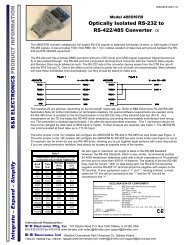
Model: <strong><strong>485</strong>PTBR</strong><br />
<strong>RS</strong>-<strong>232</strong> <strong>to</strong> <strong>RS</strong>-<strong>485</strong> <strong>Converter</strong> CE<br />
International Headquarters:<br />
707 Day<strong>to</strong>n Road P.O. Box 1040 Ottawa, IL 61350 USA<br />
815-433-5100 Fax 433-5104 www.bb-elec.com orders@bb-elec.com support@bb-elec.com<br />
Westlink Commercial Park Oranmore Co. Galway Ireland<br />
+353 91 792444 Fax +353 91 792445 www.bb-europe.com orders@bb-elec.com support@bb-europe.com<br />
<strong><strong>485</strong>PTBR</strong>-3903-1/2<br />
© 2003 by B&B Electronics. All rights reserved.<br />
Description<br />
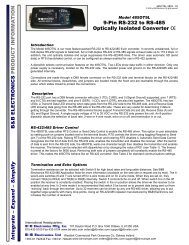
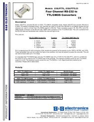
The <strong><strong>485</strong>PTBR</strong> converts unbalanced <strong>RS</strong>-<strong>232</strong> signals <strong>to</strong> balanced, full or half-duplex <strong>RS</strong>-<strong>485</strong> signals. <strong>RS</strong>-<strong>485</strong> is an<br />
enhanced version of the <strong>RS</strong>-422 Standard. It allows multiple drivers and receivers on a two-wire system. The <strong>RS</strong>-<strong>232</strong><br />
port has a female DB-9 connec<strong>to</strong>r with pins 2(RD), 3(TD), and 5(SG) supported. Pins 7(RTS) and 8(CTS) are tied<br />
<strong>to</strong>gether. Also pins 6(DSR), 1(CD), and 4(DTR) are tied <strong>to</strong>gether, but not passed through the converter. The <strong>RS</strong>-<strong>485</strong><br />
port has an 8-position pluggable terminal block connec<strong>to</strong>r.<br />
Baud Rate<br />
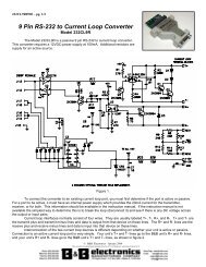
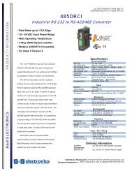
The <strong><strong>485</strong>PTBR</strong> can accept baud rates from 300 baud <strong>to</strong> 115.2K baud. In order <strong>to</strong> change the baud rate on the <strong><strong>485</strong>PTBR</strong><br />
a resis<strong>to</strong>r and possibly a capaci<strong>to</strong>r must be changed. By looking up the selected baud rate on Table 1 the resis<strong>to</strong>r and<br />
capaci<strong>to</strong>r value can be determined. Remove R3 and C7 from the printed circuit board. Place new components in the R2<br />
and C6 locations. See Figure 1 and 2 for resis<strong>to</strong>r and capaci<strong>to</strong>r locations.<br />
Biasing Resis<strong>to</strong>rs<br />
The biasing resis<strong>to</strong>rs R5 and R7 can also be altered. The <strong><strong>485</strong>PTBR</strong> comes standard with 4.7K biasing resis<strong>to</strong>rs. To<br />
change the value of biasing resis<strong>to</strong>rs, remove R5 and R7 and replace with new value in locations R4 and R6. See<br />
Figure 1 and 2 for resis<strong>to</strong>r locations.<br />
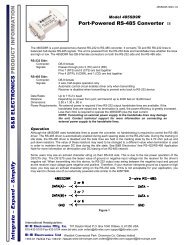
Termination Resis<strong>to</strong>r<br />
The termination resis<strong>to</strong>r location for the <strong><strong>485</strong>PTBR</strong> is located at R8. A termination resis<strong>to</strong>r can be placed in the R8<br />
location and a jumper wire placed from the terminal location <strong>to</strong> RD(B). We recommend a value of 100 <strong>to</strong> 120 ohm<br />
resis<strong>to</strong>r for termination. See Figure 2 for termination resis<strong>to</strong>r location.<br />
Constant Receiver Enable<br />
The <strong><strong>485</strong>PTBR</strong> is standard setup with the receiver disabled during transmission. The <strong><strong>485</strong>PTBR</strong> can be set up for<br />
constant receiver enable. When R9 is removed the receiver is in constant receive mode (four-wire). When R9 is in the<br />
circuit the <strong><strong>485</strong>PTBR</strong> is in half-duplex mode (two-wire). See Figure 1 for jumper location.<br />
Data Line Polarity<br />
The polarity of the two <strong>RS</strong>-<strong>485</strong> lines must be correct. With no data being sent, the <strong>RS</strong>-<strong>232</strong> line should be negative and<br />
the <strong>RS</strong>-<strong>485</strong> “A” terminal should be negative with respect <strong>to</strong> the “B” terminal. If your equipment uses a “+” and “-“ naming<br />
scheme, in most cases the “A” line will be connected <strong>to</strong> the “-“ and the “B” line will be connected <strong>to</strong> the “+”.<br />
DECLARATION OF CONFORMITY<br />
Manufacturer’s Name:<br />
B&B Electronics Manufacturing Company<br />
Manufacturer’s Address: P.O. Box 1040<br />
707 Day<strong>to</strong>n Road<br />
Ottawa, IL 61350 USA<br />
Model Number:<br />
<strong><strong>485</strong>PTBR</strong><br />
Description:<br />
<strong>RS</strong>-<strong>232</strong> <strong>to</strong> <strong>RS</strong>-<strong>485</strong> <strong>Converter</strong><br />
Type:<br />
Light industrial ITE equipment<br />
Application of Council Directive: 89/336/EEC<br />
Standards: EN 55022<br />
EN 61000-6-1<br />
EN 61000 (-4-2, -4-3, -4-4, -4-5, -4-6, -4-8, -4-11)<br />
William H. Franklin III, Direc<strong>to</strong>r of Engineering
Integrate – Expand – Simplify B&B ELECTRONICS PRODUCT INFORMATION<br />
Table 1<br />
COMPONENT REPLACEMENTS FOR<br />
CHANGING BAUD RATE TIMEOUTS<br />
Resis<strong>to</strong>r Capaci<strong>to</strong>r<br />
Baud Time<br />
(R3) (C7)<br />
Rate (ms)<br />
(ohm) (mfd)<br />
300 33.3 330K 0.1<br />
600 16.6 160K 0.1<br />
1200 8.33 820K 0.01<br />
2400 4.16 430K 0.01<br />
4800 2.08 200K 0.01<br />
9600 1.04 100K 0.01<br />
19200 .520 56K 0.01<br />
38400 .260 27K 0.01<br />
57600 .176 16K 0.01<br />
115200 .0868 8.2K 0.01<br />
International Headquarters:<br />
707 Day<strong>to</strong>n Road P.O. Box 1040 Ottawa, IL 61350 USA<br />
815-433-5100 Fax 433-5104 www.bb-elec.com orders@bb-elec.com support@bb-elec.com<br />
Westlink Commercial Park Oranmore Co. Galway Ireland<br />
+353 91 792444 Fax +353 91 792445 www.bb-europe.com orders@bb-elec.com support@bb-europe.com<br />
<strong><strong>485</strong>PTBR</strong>-3903-2/2<br />
© 2003 by B&B Electronics. All rights reserved.<br />
Figure 1. PC Board Layout - Top<br />
Figure 2. PC Board Layout - Bot<strong>to</strong>m