Vlinx MESR9xx Modbus Gateway
Vlinx MESR9xx Modbus Gateway
Vlinx MESR9xx Modbus Gateway

You also want an ePaper? Increase the reach of your titles
YUMPU automatically turns print PDFs into web optimized ePapers that Google loves.
<strong>Vlinx</strong><strong>MESR9xx</strong><strong>Modbus</strong> <strong>Gateway</strong>Manual Documentation Number <strong>MESR9xx</strong>-0109mwww.bb-elec.comwww.bb-europe.com
<strong>Vlinx</strong> <strong>MESR9xx</strong>Documentation Number: <strong>MESR9xx</strong>-0109mThis product was designed and manufactured in Ottawa, Illinois USAUsing domestic and imported parts byInternational HeadquartersB&B Electronics Mfg. Co. Inc.707 Dayton RoadOttawa, IL 61350 USAPhone (815) 433-5100 -- General Fax (815) 433-5105Website: www.bb-elec.comEuropean HeadquartersB&B Electronics Ltd.Westlink Commercial ParkOranmore, Co. Galway, IrelandPhone +353 91-792444 -- Fax +353 91-792445Website: www.bb-europe.comRevision – One – January 2009©2009 B&B Electronics Mfg. Co. Inc. No part of this publication may be reproduced or transmitted in anyform or by any means, electronic or mechanical, including photography, recording, or any informationstorage and retrieval system without written consent. Information in this manual is subject to changewithout notice, and does not represent a commitment on the part of B&B Electronics Mfg. Co. Inc.B&B Electronics Mfg. Co. Inc. shall not be liable for incidental or consequential damages resulting fromthe furnishing, performance, or use of this manual.All brand names used in this manual are the registered trademarks of their respective owners. The use of trademarks or other designations in thispublication is for reference purposes only and does not constitute an endorsement by the trademark holder.Manual Documentation Number <strong>MESR9xx</strong>-0109mwww.bb-elec.comwww.bb-europe.com
Table of ContentsTable of Contents1. Introduction ....................................................................................................................................................... 1About <strong>MESR9xx</strong> <strong>Modbus</strong> <strong>Gateway</strong>s .......................................................................................................................................... 1<strong>MESR9xx</strong> <strong>Modbus</strong> <strong>Gateway</strong> Model Numbering ......................................................................................................................... 2List of <strong>MESR9xx</strong> <strong>Modbus</strong> <strong>Gateway</strong> Models ............................................................................................................................... 3<strong>MESR9xx</strong> <strong>Modbus</strong> <strong>Gateway</strong> Features ....................................................................................................................................... 4<strong>Vlinx</strong> Manager Configuration Software ....................................................................................................................................... 52. <strong>MESR9xx</strong> <strong>Modbus</strong> <strong>Gateway</strong> Hardware ............................................................................................................ 6Package Checklist ...................................................................................................................................................................... 6<strong>MESR9xx</strong> <strong>Modbus</strong> <strong>Gateway</strong> Enclosures and Mounting ............................................................................................................. 6LED Indicators ............................................................................................................................................................................ 7E1/E2 Ethernet Link LED .............................................................................................................................................. 7Ready LED ..................................................................................................................................................................... 7Serial Port LEDs ............................................................................................................................................................ 7Mode Switch ............................................................................................................................................................................... 8Ethernet Connector .................................................................................................................................................................... 8Fiberoptic Connectors ................................................................................................................................................................ 9Serial Port Connectors ............................................................................................................................................................... 9Power Connector ..................................................................................................................................................................... 10Mounting Hardware .................................................................................................................................................................. 103. <strong>Modbus</strong> <strong>Gateway</strong> Setup and Connections ................................................................................................... 12Connecting the Power Supply .................................................................................................................................................. 12Connecting <strong>MESR9xx</strong> <strong>Modbus</strong> <strong>Gateway</strong>s to <strong>Modbus</strong> networks .............................................................................................. 12Connecting the MESR9x1-x ......................................................................................................................................... 13Connecting the MESR9x2T-x ....................................................................................................................................... 14Connecting the MESR9x2D-x ....................................................................................................................................... 14Connecting <strong>MESR9xx</strong> <strong>Modbus</strong> <strong>Gateway</strong>s to a Network .......................................................................................................... 15Network Connection (10BaseT/100BaseTX) ................................................................................................................ 15Fiberoptic Connection ................................................................................................................................................. 15<strong>MESR9xx</strong> <strong>Modbus</strong> <strong>Gateway</strong> Configuration Connections ......................................................................................................... 15Configuring the <strong>MESR9xx</strong> <strong>Modbus</strong> <strong>Gateway</strong> via the Network Connection .................................................................. 16Configuring the <strong>MESR9xx</strong> <strong>Modbus</strong> <strong>Gateway</strong> on Networks without a DHCP Server ................................................... 17Configuring the <strong>MESR9xx</strong> <strong>Modbus</strong> <strong>Gateway</strong> via the Serial Port (Console Mode) ...................................................... 20<strong>MESR9xx</strong> <strong>Modbus</strong> <strong>Gateway</strong> Operational Connections ............................................................................................................ 21Using <strong>MESR9xx</strong> <strong>Modbus</strong> <strong>Gateway</strong>s in Direct IP Mode ............................................................................................... 21Initiating a Hardware Reset on the <strong>Modbus</strong> <strong>Gateway</strong> .............................................................................................................. 22Reloading Factory Defaults ...................................................................................................................................................... 224. Description, <strong>Modbus</strong> <strong>Gateway</strong> Properties .................................................................................................... 23Attached ................................................................................................................................................................................... 23Baud Rate ................................................................................................................................................................................ 23Character Timeout ................................................................................................................................................................... 23Configuration Files ................................................................................................................................................................... 23Data/Parity/Stop ....................................................................................................................................................................... 24Default <strong>Gateway</strong> ....................................................................................................................................................................... 24DHCP ....................................................................................................................................................................................... 24Firmware Version ..................................................................................................................................................................... 25Hardware Version .................................................................................................................................................................... 25ID Routing ................................................................................................................................................................................ 25IP Address ................................................................................................................................................................................ 25Link Status ............................................................................................................................................................................... 26MAC Address ........................................................................................................................................................................... 26<strong>Modbus</strong> Priority ........................................................................................................................................................................ 26<strong>Modbus</strong> Serial Retries .............................................................................................................................................................. 26<strong>Modbus</strong> ASCII .......................................................................................................................................................................... 26Page iManual Documentation Number <strong>MESR9xx</strong>-0109mwww.bb-elec.com/www.bb-europe.com/
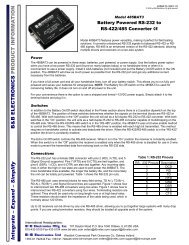
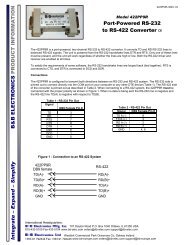
1. Introduction <strong>Vlinx</strong> <strong>MESR9xx</strong> <strong>Modbus</strong> <strong>Gateway</strong>1. IntroductionThank you for purchasing a <strong>MESR9xx</strong> <strong>Modbus</strong> <strong>Gateway</strong> product! This product has beenmanufactured to the highest standards of quality and performance to ensure yourcomplete satisfaction.Figure 1. An MESR921 <strong>Modbus</strong> <strong>Gateway</strong>About <strong>MESR9xx</strong> <strong>Modbus</strong> <strong>Gateway</strong>s<strong>MESR9xx</strong> <strong>Modbus</strong> <strong>Gateway</strong>s connect <strong>Modbus</strong> networks (RS-232, RS-422 or RS-485)to Ethernet networks, allowing the <strong>Modbus</strong> network to become a node on the network.The serial ports can be accessed over a LAN/WAN using Direct IP Mode connections.<strong>MESR9xx</strong> <strong>Modbus</strong> <strong>Gateway</strong>s feature 10BaseT or 100BaseTX copper network media andfiber optic media options, depending on the model. <strong>MESR9xx</strong> <strong>Modbus</strong> <strong>Gateway</strong>s arebuilt for use in industrial environments, featuring an IP30 approved slim line DIN railmountable case. They operate from a range of DC power supply voltages and featurepluggable terminal block power connectors. An external power supply, sold separately, isrequired. The photograph above is an MESR921 gateway. The MESR92x units have anadditional Ethernet port which functions much like an Ethernet Switch. MESR90x unitshave one Ethernet port.Page 1Manual Documentation Number <strong>MESR9xx</strong>-0109mwww.bb-elec.com/www.bb-europe.com/
1. Introduction <strong>Vlinx</strong> <strong>MESR9xx</strong> <strong>Modbus</strong> <strong>Gateway</strong><strong>MESR9xx</strong> <strong>Modbus</strong> <strong>Gateway</strong> Model Numbering<strong>MESR9xx</strong> <strong>Modbus</strong> <strong>Gateway</strong>s are a growing family of products. Models are availablewith one or two serial connections. Network connection options include10BaseT/100BaseTX copper or several different fiber optic options. The followingdiagram shows the model numbering scheme:Page 2Manual Documentation Number <strong>MESR9xx</strong>-0109mwww.bb-elec.com/www.bb-europe.com/
1. Introduction <strong>Vlinx</strong> <strong>MESR9xx</strong> <strong>Modbus</strong> <strong>Gateway</strong>Model NumberMESR902T-SC40MESR902T-ST80MESR902T-SC80MESR901MESR901-MTMESR901-MCMESR901-STMESR901-SCMESR901-ST40MESR901-SC40MESR901-ST80MESR901-SC80Features1 Single-mode 40 Km SC, 2 port MEI with TB1 Single-mode 80 Km ST, 2 port MEI with TB1 Single-mode 80 Km SC, 2 port MEI with TB1 RJ45 Copper, 1 port MEI with TB/DB9 Male1 Multi-mode ST, 1 port MEI with TB/DB9 Male1 Multi-mode SC, 1 port MEI with TB/DB9 Male1 Single-mode ST, 1 port MEI with TB/DB9 Male1 Single-mode SC, 1 port MEI with TB/DB9 Male1 Single-mode 40 Km ST, 1 port MEI with TB/DB9 Male1 Single-mode 40 Km SC, 2 port MEI with DB9 Male1 Single-mode 80 Km ST, 1 port MEI with TB/DB9 Male1 Single-mode 80 Km SC, 1 port MEI with TB/DB9 Male<strong>MESR9xx</strong> <strong>Modbus</strong> <strong>Gateway</strong> Features• Four series models• MESR901-x (single serial port, single Ethernet Port)• MESR902T-x (two serial ports with pluggable terminal blocks, single Ethernetport)• MESR921-x (single serial port, two Ethernet Ports)• MESR922T-x (two serial ports with pluggable terminal blocks, two EthernetPorts)• On models with two Ethernet Ports, the second port is an Ethernet passthroughport. This port functions much like an unmanaged switch.Page 4• Fiber models available for each of the above series• Multi-interface serial ports• DB-9M and pluggable terminal block serial port connector options• All ports are software selectable as RS-232, RS-422 or RS-485 2- and 4-wire• Configuration can be done via network or direct serial connection• Slim line DIN rail mountable case• Accepts DC power over a wide voltage rangeManual Documentation Number <strong>MESR9xx</strong>-0109mwww.bb-elec.com/www.bb-europe.com/
1. Introduction <strong>Vlinx</strong> <strong>MESR9xx</strong> <strong>Modbus</strong> <strong>Gateway</strong>• 10/100 Mbps Ethernet with Auto Selection, Auto MDI/MDIX• LAN and WAN Communications• TCP Client or Server operation - configurable• Firmware Upload for future revisions/upgrades• Software Support - Windows 2000/2003 Server/XP/Vista x32• Configuration of Ethernet and serial port settings using <strong>Vlinx</strong> Manager software<strong>Vlinx</strong> Manager Configuration Software<strong>Vlinx</strong> Manager configuration software enables you to find connected <strong>Modbus</strong> gateways,configure them, upgrade <strong>Modbus</strong> gateway firmware, and save/load configuration files. Itfeatures a graphical user interface (GUI) that is convenient and easy to use.Page 5Manual Documentation Number <strong>MESR9xx</strong>-0109mwww.bb-elec.com/www.bb-europe.com/
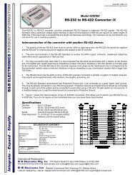
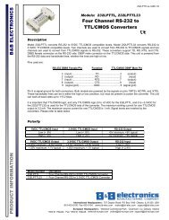
2. Hardware <strong>Vlinx</strong> <strong>MESR9xx</strong> <strong>Modbus</strong> <strong>Gateway</strong>2. <strong>MESR9xx</strong> <strong>Modbus</strong> <strong>Gateway</strong> Hardware<strong>MESR9xx</strong> <strong>Modbus</strong> <strong>Gateway</strong>s are enclosed in DIN rail mountable enclosures and featureLED indicators, power, Ethernet and serial connectors and a recessed Mode switch.Package Checklist<strong>MESR9xx</strong> <strong>Modbus</strong> <strong>Gateway</strong>s are shipped with the following items included:• <strong>MESR9xx</strong> <strong>Modbus</strong> <strong>Gateway</strong> Module• Quick Start Guide• CD with User Manual, Quick Start Guide and firmware<strong>MESR9xx</strong> <strong>Modbus</strong> <strong>Gateway</strong> Enclosures and MountingAll <strong>MESR9xx</strong> <strong>Modbus</strong> <strong>Gateway</strong> models are built into similar enclosures. Modules areDIN rail mountable. The MESR92x (shown below) enclosure is larger than theMESR90x.See the specification table for dimensions.Figure 2. Front View of an MESR921 <strong>Modbus</strong> <strong>Gateway</strong>Page 6Manual Documentation Number <strong>MESR9xx</strong>-0109mwww.bb-elec.com/www.bb-europe.com/
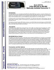
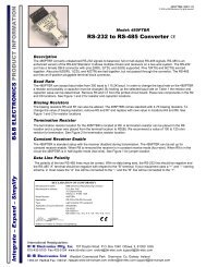
2. Hardware <strong>Vlinx</strong> <strong>MESR9xx</strong> <strong>Modbus</strong> <strong>Gateway</strong>LED Indicators<strong>MESR9xx</strong> <strong>Modbus</strong> <strong>Gateway</strong>s have three types of LED indicators: Ethernet Link LEDs,a Ready LED and Serial Port LEDs.Figure 3. Ready Ethernet Port LEDs on 1 and 2 Ethernet Port <strong>Modbus</strong> <strong>Gateway</strong>sE1/E2 Ethernet Link LEDThe Ethernet Link LED (E1 or E2) illuminates (green) if the Ethernet is connected.When the LED is blinking it indicates that there is data traffic on the Ethernet link.E1 is used for all models to connect to the network. E2 is used on MESR92X models, andis a pass-through Ethernet connector.Ready LEDThe Ready LED (green) blinks if the system is operating correctly, once per second innormal operating conditions, or three times per second in reset, configuration mode, orwhen loading factory defaults. If the LED is off or steady, it indicates the system is notoperating correctly.Serial Port LEDsMESR901-x <strong>Modbus</strong> <strong>Gateway</strong>s feature one serial port. MESR902D, and MESR902T-x<strong>Modbus</strong> <strong>Gateway</strong>s feature two serial ports. Each serial port has an associated LED. SerialPort LEDs blink (green) when data is being transmitted or received on the serial port.When the LED is On it indicates the serial port is open.Figure 4. Serial Port LEDs on 1 and 2 Serial Port <strong>Modbus</strong> <strong>Gateway</strong>sPage 7Manual Documentation Number <strong>MESR9xx</strong>-0109mwww.bb-elec.com/www.bb-europe.com/
2. Hardware <strong>Vlinx</strong> <strong>MESR9xx</strong> <strong>Modbus</strong> <strong>Gateway</strong>Mode SwitchA recessed momentary reset switch is located on the top of the enclosure. To activate theswitch, insert a small plastic tool through the hole in the enclosure and press lightly.Figure 5. Mode SwitchThe Mode switch can be used to:• Initiate a Hardware Reset• Enter Console Mode• Reload factory defaultsNote: Refer to Section 3. <strong>Modbus</strong> <strong>Gateway</strong> Setup and Connections for more information on usingthe Mode switch.Ethernet Connector<strong>Modbus</strong> gateway models using 10BaseT/100BaseTX network connections use an RJ45receptacle. The <strong>Modbus</strong> gateway is connected to a standard Ethernet network drop usinga straight-through RJ45 (male) Ethernet cable.Figure 6. Ethernet Connectors. E2 is pass-through connection on model shownNote: Refer to Appendix D for connection pin-outs.Page 8Manual Documentation Number <strong>MESR9xx</strong>-0109mwww.bb-elec.com/www.bb-europe.com/
2. Hardware <strong>Vlinx</strong> <strong>MESR9xx</strong> <strong>Modbus</strong> <strong>Gateway</strong>Fiberoptic Connectors<strong>Modbus</strong> gateway models using fiber optic network connections use either SC or STconnectors, depending on the specific model.Figure 7. SC and ST Fiberoptic Cable ConnectorsSerial Port Connectors<strong>MESR9xx</strong> <strong>Modbus</strong> <strong>Gateway</strong>s use four serial port connector configurations, depending onthe model:• MESR901-x <strong>Modbus</strong> <strong>Gateway</strong>s feature one serial port and use a DB-9Mconnector for RS-232 and a five-position removeable terminal block for RS-422and RS-485 connections.• MESR902T-x <strong>Modbus</strong> <strong>Gateway</strong>s feature two serial ports, both using five-positionremovable terminal blocks for RS-232, RS-422 and RS-485 connections.• MESR921-x <strong>Modbus</strong> <strong>Gateway</strong>s feature one serial port and use a DB-9Mconnector for RS-232 and a five-position removeable terminal block for RS-422and RS-485 connections.• MESR922T-x <strong>Modbus</strong> <strong>Gateway</strong>s feature two serial ports, both using five-positionremovable terminal blocks for RS-232, RS-422 and RS-485 connections.Figure 8. DB-9 Female Serial Port ConnectorPage 9Manual Documentation Number <strong>MESR9xx</strong>-0109mwww.bb-elec.com/www.bb-europe.com/
2. Hardware <strong>Vlinx</strong> <strong>MESR9xx</strong> <strong>Modbus</strong> <strong>Gateway</strong>Figure 9. Five-Position Pluggable Terminal BlockNote: Refer to Appendix D for connection pin-outs.Power ConnectorThe power connector is a 2-position pluggable terminal block.Figure 10.Power ConnectionMounting Hardware<strong>MESR9xx</strong> <strong>Modbus</strong> <strong>Gateway</strong> modules can be DIN rail mounted. The DIN mounting clipand spring is included on each module.Page 10Manual Documentation Number <strong>MESR9xx</strong>-0109mwww.bb-elec.com/www.bb-europe.com/
2. Hardware <strong>Vlinx</strong> <strong>MESR9xx</strong> <strong>Modbus</strong> <strong>Gateway</strong>Figure 11.DIN Clips on <strong>Modbus</strong> <strong>Gateway</strong> Modules. Large DIN clips are used on MESR92x, small DIN clips on MESR90x.Page 11Manual Documentation Number <strong>MESR9xx</strong>-0109mwww.bb-elec.com/www.bb-europe.com/
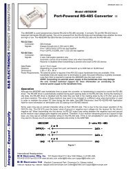
3. Setup and Connections <strong>Vlinx</strong> <strong>MESR9xx</strong> <strong>Modbus</strong> <strong>Gateway</strong>3. <strong>Modbus</strong> <strong>Gateway</strong> Setup and ConnectionsThis section describes how to setup and connect <strong>MESR9xx</strong> <strong>Modbus</strong> <strong>Gateway</strong>s.Note: In this section devices to be connected to the <strong>Modbus</strong> gateway’s serial connection are simplyreferred to as the “<strong>Modbus</strong> network”.Connecting the Power SupplyConnect a DC power supply to the power terminals on the top of the <strong>Modbus</strong> gateway.Polarity of the wires is indicated on the label on the side of the <strong>Modbus</strong> gateway.Acceptable voltages are between 10 VDC and 48 VDC. The power supply must becapable of supplying 4 Watts for MESR90x units or 6 Watts fro MESR92x units.Figure 12.MESR Power ConnectionConnecting <strong>MESR9xx</strong> <strong>Modbus</strong> <strong>Gateway</strong>s to <strong>Modbus</strong> networks<strong>MESR9xx</strong> <strong>Modbus</strong> <strong>Gateway</strong>s can be configured to connect to <strong>Modbus</strong> networks usingRS-232, RS-422, RS-485 2-wire and RS-485 4-wire.Page 12Manual Documentation Number <strong>MESR9xx</strong>-0109mwww.bb-elec.com/www.bb-europe.com/
3. Setup and Connections <strong>Vlinx</strong> <strong>MESR9xx</strong> <strong>Modbus</strong> <strong>Gateway</strong>RS-232 connections support eight signal lines plus Signal Ground. Signals are singleended and referenced to Ground. Default communications parameters are 9600, 8, N, 1and no flow control implemented.RS-422 connections support two signal pairs: RXA(-), RXB(+) and TXA(-), TXA(+),plus GND. The data lines are differential pairs (A & B) in which the B line is positiverelative to the A line in the idle (mark) state. Ground provides a common mode reference.RS-485 connections support 2-wire or 4-wire operation.When configured for 4-wire operation the connection supports two signal pairs: RXA(-),RXB(+) and TXA(-), TXA(+), plus GND. This makes full-duplex operation possible.The data lines are differential pairs (A & B) in which the B line is positive relative to theA line in the idle (mark) state. Ground provides a common mode reference.When configured for 2-wire operation the connection supports one signal pair: DataB(+)and DataA(-) signal channels using half-duplex operation. The data lines are differentialwith the Data B line positive relative to Data A in the idle (mark) state. Ground providesa common mode reference.Connecting the MESR9x1-xThe MESR9x1-x has one serial connection that supports RS-232, RS-422 and RS-485(2- and 4-wire). The unit has two connectors: a DB-9M connector and a 5-positionterminal block.If you select RS-232 mode when you configure the <strong>Modbus</strong> gateway, you must connectthe <strong>Modbus</strong> network to the <strong>Modbus</strong> gateway via a serial cable. The MESR901 is a DTE.If the <strong>Modbus</strong> network is a DTE, use a null modem (cross-over) cable. If the <strong>Modbus</strong>network is a DCE, use a straight-through cable.If you select RS-422 mode, RS-485 2-wire mode, or RS-485 4-wire mode when youconfigure the <strong>Modbus</strong> gateway, you must connect the <strong>Modbus</strong> network appropriately, viathe 5-position terminal block.Note: Refer to Appendix D for connector pinout information.Page 13Manual Documentation Number <strong>MESR9xx</strong>-0109mwww.bb-elec.com/www.bb-europe.com/
3. Setup and Connections <strong>Vlinx</strong> <strong>MESR9xx</strong> <strong>Modbus</strong> <strong>Gateway</strong>Figure 13.MESR901 ConnectionsConnecting the MESR9x2T-xThe MESR9x2T-x has two serial connections that support RS-232, RS-422 and RS-485(2- and 4-wire). The unit has two connectors, both of which are 5-position terminalblocks. Make the appropriate connections to the terminal blocks to match the serialconnection mode you select when configuring the <strong>Modbus</strong> gateway.Note: Refer to Appendix D for connector pinout information.Figure 14.MESR902T-x ConnectionsConnecting the MESR9x2D-xThe MESR9x2D-x has two serial connections that support RS-232, RS-422 and RS-485(2- and 4-wire). The unit has two connectors, both of which are DB-9M connectors. Youmust connect the <strong>Modbus</strong> network to the <strong>Modbus</strong> gateway via a serial cable. TheMESR902D is a DTE. If the <strong>Modbus</strong> network is a DTE, use a null modem (cross-over)cable. If the <strong>Modbus</strong> network is a DCE, use a straight-through cable.Note: Refer to Appendix D for connector pin-out information.Page 14Manual Documentation Number <strong>MESR9xx</strong>-0109mwww.bb-elec.com/www.bb-europe.com/
3. Setup and Connections <strong>Vlinx</strong> <strong>MESR9xx</strong> <strong>Modbus</strong> <strong>Gateway</strong>Figure 15.MESR902D-x ConnectionsConnecting <strong>MESR9xx</strong> <strong>Modbus</strong> <strong>Gateway</strong>s to a NetworkNetwork Connection (10BaseT/100BaseTX)When connecting a <strong>Modbus</strong> gateway equipped with a 10BaseT/100BaseTX networkconnection (RJ45 connector) a standard network cable is connected from the <strong>Modbus</strong>gateway to a network drop. PCs configuring and/or communicating with the <strong>Modbus</strong>gateway are also connected to the network.Fiberoptic ConnectionWhen connecting a <strong>Modbus</strong> gateway equipped with a fiberoptic interface to afiberoptic link the appropriate fiberoptic cable must be connected between the <strong>Modbus</strong>gateway and the network interface. Refer to Figure 2, “List of <strong>MESR9xx</strong> <strong>Modbus</strong><strong>Gateway</strong> Models” at the beginning of this manual for a list of supported fiber types,distances and connectors.<strong>MESR9xx</strong> <strong>Modbus</strong> <strong>Gateway</strong> Configuration Connections<strong>MESR9xx</strong> <strong>Modbus</strong> <strong>Gateway</strong>s can be configured over the network or via a serial port.Page 15Manual Documentation Number <strong>MESR9xx</strong>-0109mwww.bb-elec.com/www.bb-europe.com/
3. Setup and Connections <strong>Vlinx</strong> <strong>MESR9xx</strong> <strong>Modbus</strong> <strong>Gateway</strong>Configuring the <strong>MESR9xx</strong> <strong>Modbus</strong> <strong>Gateway</strong> via the Network ConnectionWhen configuring via the network, either <strong>Vlinx</strong> Manager software or the web interfacecan be used.Configuring with <strong>Vlinx</strong> Manager<strong>MESR9xx</strong> <strong>Modbus</strong> <strong>Gateway</strong>s can be configured over the network <strong>Vlinx</strong> Managersoftware running on a PC.To open <strong>Vlinx</strong> Manager:1. From the Desktop, click Start Programs B&B Electronics <strong>Vlinx</strong> <strong>Modbus</strong><strong>Gateway</strong> Manager Configuration Manager.The <strong>Vlinx</strong> Manager Device Discovery window appears.Figure 16.<strong>Vlinx</strong> Manager Discovery Window2. Configure your <strong>Modbus</strong> gateway as required.Note: For more information on configuration options refer to Section 4: Description of <strong>Modbus</strong>gateway Properties.Configuring with the Web Interface<strong>MESR9xx</strong> <strong>Modbus</strong> <strong>Gateway</strong>s can be configured over the network using a standardinternet browser such as Internet Explorer or Firefox.To open the web configuration interface:1. On a PC connected to the network, open a browser.Page 16Manual Documentation Number <strong>MESR9xx</strong>-0109mwww.bb-elec.com/www.bb-europe.com/
3. Setup and Connections <strong>Vlinx</strong> <strong>MESR9xx</strong> <strong>Modbus</strong> <strong>Gateway</strong>2. In the browser’s address bar, type the IP address of the <strong>Modbus</strong> gateway.Note: Your <strong>Modbus</strong> gateway comes from the factory pre-configured to receive an IP addressassignment from a DHCP server. If a DHCP Server is not available on your network, it will defaultto 169.254.102.39.The web interface Login page appears.Figure 17.<strong>Vlinx</strong> Manager Login Screen3. Configure your <strong>Modbus</strong> gateway as required.Note: For more information on configuration options refer to Section 4: Description of <strong>Modbus</strong><strong>Gateway</strong> Properties.Configuring the <strong>MESR9xx</strong> <strong>Modbus</strong> <strong>Gateway</strong> on Networks without a DHCPServerYour <strong>Modbus</strong> <strong>Gateway</strong> comes from the factory set up to receive an IP assignment from aDHCP Server. If there is not a DHCP server on your network, the <strong>Modbus</strong> <strong>Gateway</strong> willdefault to IP address 169.254.102.39. If this address does not work with your PC, thereare two methods to manually configure the network information.1. Method 1: Change your PC Network to Match the <strong>Modbus</strong> <strong>Gateway</strong>a. Open your network connectionPage 17Manual Documentation Number <strong>MESR9xx</strong>-0109mwww.bb-elec.com/www.bb-europe.com/
3. Setup and Connections <strong>Vlinx</strong> <strong>MESR9xx</strong> <strong>Modbus</strong> <strong>Gateway</strong>b. Click on Internet Protocol (TCP/IP) and click . Change theparameters to the following:IP Address = 169.254.102.1Subnet Mask = 255.255.0.0Default <strong>Gateway</strong> = 169.254.102.100c. Use the <strong>Vlinx</strong> Manager Software to search for, discover, and configure the<strong>Modbus</strong> <strong>Gateway</strong>.Page 18Manual Documentation Number <strong>MESR9xx</strong>-0109mwww.bb-elec.com/www.bb-europe.com/
3. Setup and Connections <strong>Vlinx</strong> <strong>MESR9xx</strong> <strong>Modbus</strong> <strong>Gateway</strong>2. Method 2: Change the <strong>Modbus</strong> <strong>Gateway</strong>’s network settings to match your PC usingConsole Modea. Connect a null modem serial cable (crossover cable) from port 1 on the<strong>Modbus</strong> <strong>Gateway</strong> to an available COM port on your PC.b. Open Hyper Terminal or similar serial emulation software and connect to theCOM port used in step one. Ensure the port is configured to 115,200 baud, 8data bits, no parity, and 1 stop bit.c. Enter Console Mode. Press and hold the <strong>Modbus</strong> <strong>Gateway</strong>’s for 2 to 10seconds. The LED indicators will respond as follows:Model Port 1 LED Port 2 LED Ready LEDMESR9x1 OFF XXXXXXX ONMESR9x2 OFF ON OFFd. Release the reset button. The READY LED will blink once per second for fiveseconds. This indicates that the <strong>Modbus</strong> <strong>Gateway</strong> is re-booting in ConsoleMode.e. When the <strong>Modbus</strong> <strong>Gateway</strong> has successfully restarted in Console Mode, theREADY LED will be OFF and the PORT 1 LED will be ON.f. Open the <strong>Vlinx</strong> Manager Software and select “Serial Port” as the method toconnect to the <strong>Modbus</strong> <strong>Gateway</strong>.g. After logging in, click on .h. Un-check the box next to “I Want DHCP to setup the Network.”i. Re-configure the <strong>Modbus</strong> <strong>Gateway</strong>’s network settings to something within therange of your PC’s network settings. For example:PC Network SettingsIP Address = 192.168.0.1Subnet Mask = 255.255.0.0Default <strong>Gateway</strong> = 192.168.0.100Change the <strong>Modbus</strong> <strong>Gateway</strong>’s network settings to:IP Address = 192.168.0.50Subnet Mask = 255.255.0.0Default <strong>Gateway</strong> = 192.168.0.100Page 19Manual Documentation Number <strong>MESR9xx</strong>-0109mwww.bb-elec.com/www.bb-europe.com/
3. Setup and Connections <strong>Vlinx</strong> <strong>MESR9xx</strong> <strong>Modbus</strong> <strong>Gateway</strong>j. Save the settings and remove power from the <strong>Modbus</strong> <strong>Gateway</strong>.k. Re-apply power. Open the <strong>Vlinx</strong> Manager Software and select “Network”as the method to connect to the device.Configuring the <strong>MESR9xx</strong> <strong>Modbus</strong> <strong>Gateway</strong> via the Serial Port (ConsoleMode)Your <strong>Modbus</strong> gateway can be configured via a serial port using <strong>Vlinx</strong> Manager. To usethis feature the <strong>Modbus</strong> gateway's serial port must be connected to the serial port of a PC(using a null modem cable).Figure 18.Console Mode SetupTo configure the <strong>Modbus</strong> gateway it must be put into Console Mode, using the Modeswitch.To enter Console Mode, press and hold the Mode switch for between two and tenseconds. The LED indicators respond as follows:1. The Ready LED blinks three times per second while the button is being pressed.2. The <strong>Modbus</strong> gateway is in Console Mode when:• On the MESR901: Port 1 LED is On and the Ready LED is Off.• On MESR902x models: Port 1 LED is On and the Port 2 LED is Off.To configure the <strong>Modbus</strong> gateway, open the <strong>Vlinx</strong> Manager software and set up the<strong>Modbus</strong> gateway's parameters as required.Note: For more information on configuration options refer to Section 4: Description of <strong>Modbus</strong><strong>Gateway</strong> Properties.To exit Console Mode, press and hold the Reset switch for two seconds, or turn off thepower from the <strong>MESR9xx</strong>, wait a few seconds, and turn the power on again.Page 20Manual Documentation Number <strong>MESR9xx</strong>-0109mwww.bb-elec.com/www.bb-europe.com/
3. Setup and Connections <strong>Vlinx</strong> <strong>MESR9xx</strong> <strong>Modbus</strong> <strong>Gateway</strong>The LEDs go back to their normal states when the device resumes normal operation.<strong>MESR9xx</strong> <strong>Modbus</strong> <strong>Gateway</strong> Operational Connections<strong>MESR9xx</strong> <strong>Modbus</strong> <strong>Gateway</strong>s can operate in Direct IP Mode.Using <strong>MESR9xx</strong> <strong>Modbus</strong> <strong>Gateway</strong>s in Direct IP ModeA Direct IP connection allows applications using TCP/IP socket programs tocommunicate with the COM ports on the <strong>Modbus</strong> gateway. In this type of application the<strong>Modbus</strong> gateway is configured as a TCP server. The socket program running on the PCestablishes a communication connection with the <strong>Modbus</strong> gateway. The data is sentdirectly to and from the serial port on the server.To set up a Direct IP Mode connection:1. Connect the <strong>Modbus</strong> gateway to the network and a <strong>Modbus</strong> network as described inprevious sections.2. Configure the <strong>Modbus</strong> gateway with the appropriate network settings (using <strong>Vlinx</strong>Manager or the web interface).3. Configure your software application with the appropriate IP address and port numberto communicate with the <strong>Modbus</strong> network(s).Figure 19.Direct IP ConnectionPage 21Manual Documentation Number <strong>MESR9xx</strong>-0109mwww.bb-elec.com/www.bb-europe.com/
3. Setup and Connections <strong>Vlinx</strong> <strong>MESR9xx</strong> <strong>Modbus</strong> <strong>Gateway</strong>Initiating a Hardware Reset on the <strong>Modbus</strong> <strong>Gateway</strong>To initiate a Hardware Reset on the <strong>Modbus</strong> gateway, press and hold the Mode switchfor 0 to 2 seconds, and then release it. The LED indicators respond as follows:1. The Ready LED blinks three times per second while the button is being pressed.2. The <strong>Modbus</strong> gateway is in Reset Mode when:• On the MESR901: Port 1 LED is On and the Ready LED is Off.• On MESR902x models: Port 1 LED is On and the Port 2 LED is Off.3. The LEDs go back to their normal states when the device resumes normal operation.Reloading Factory DefaultsTo reload Factory Defaults, press and hold the Mode switch for more than 10 seconds.The LED indicators respond as follows:1. The Ready LED blinks three times per second while the button is being pressed.2. The <strong>Modbus</strong> gateway is in Factory Default Mode when:• On the MESR901: Port 1 LED and the Ready LED are both On.• On MESR902x models: Port 1 LED and the Port 2 LED are both On.The <strong>Modbus</strong> gateway reloads all factory default configuration parameters.3. The LEDs go back to their normal states when the device resumes normal operation.Note: Factor default parameters are listed in Appendix APage 22Manual Documentation Number <strong>MESR9xx</strong>-0109mwww.bb-elec.com/www.bb-europe.com/
4. Properties <strong>Vlinx</strong> <strong>MESR9xx</strong> <strong>Modbus</strong> <strong>Gateway</strong>4. Description, <strong>Modbus</strong> <strong>Gateway</strong> PropertiesThe following <strong>MESR9xx</strong> <strong>Modbus</strong> <strong>Gateway</strong> properties are ordered alphabetically to assistyou in finding the information you need.AttachedThe Attached is selectable between Master and Slaves. If Master is selected, it will run inTCP server mode, if Slaves is selected, it will run in TCP client mode.Baud RateBaud Rate is the communication speed of the link between the <strong>Modbus</strong> gateway and thedevice attached to its serial port. Both these devices must be configured to operate at thesame baud rate. Baud rate values range from 75 to 230,400 Baud. (Refer to Appendix Bfor specific baud rates that are supported.)Character TimeoutCharacter Timeout controls the maximum duration between received characters beforesending the characters to the network. Larger values may decrease the number of networkpackets, but increase the amount of time to receive characters. Smaller values mayincrease the number of network packets, but decrease the amount of time to receivecharacters. The range is 1 through 65535.Configuration FilesConfiguration files contain all configuration settings for the <strong>Modbus</strong> gateway. When the<strong>Modbus</strong> gateway settings have been configured you can save the settings using <strong>Vlinx</strong>Manager. Existing configuration files can be Opened (from <strong>Vlinx</strong> Manager), which loadsthem into the <strong>Modbus</strong> gateway. This allows the same configuration to be applied tomultiple <strong>Modbus</strong> gateways, or to reload a previously used configuration.Page 23Manual Documentation Number <strong>MESR9xx</strong>-0109mwww.bb-elec.com/www.bb-europe.com/
4. Properties <strong>Vlinx</strong> <strong>MESR9xx</strong> <strong>Modbus</strong> <strong>Gateway</strong>Data/Parity/StopThe number of Data bits, type of Parity and number of Stop bits selected define theserial port parameters at which the <strong>Modbus</strong> gateway will operate. These parameters mustbe configured to match the parameters set on the <strong>Modbus</strong> network connected to the<strong>Modbus</strong> gateway's serial port.Data Bits controls the number of bits of data in each character. Options include 5, 6, 7 or8 data bits.Parity controls the error checking mode. Options are No Parity, Odd, Even, Mark orSpace.Stop Bits controls the number of bits to indicate the end of a character. Options include1, 1.5 and 2. (1.5 bits is only valid when 5 data bits is selected, which is rare. The 2 stopbits setting is only valid when 6, 7 or 8 data bits is selected.)Default <strong>Gateway</strong>DHCPThe Default <strong>Gateway</strong> address sets the default route to remote networks, enabling usersto access the <strong>Modbus</strong> gateway from outside the local network.DHCP (Dynamic Host Configuration Protocol) is a protocol used on special serversthat supply IP addresses to network nodes on request.When DHCP is enabled on the <strong>Modbus</strong> gateway (factory default), on power up it sends aDHCP request to the DHCP server, which assigns a dynamic IP address, subnet mask,and default server to the <strong>Modbus</strong> gateway.When DHCP is disabled (static IP addressing), the IP Address, Subnet and Default<strong>Gateway</strong> fields must be set manually by entering the appropriate addresses in these fields.If you do not know what addresses to use in these fields, ask your network administrator.Notes:A dynamic address assigned by the DHCP server may change if the server loses the Ethernetconnection or power is removed. If a device on the network that normally communicates with the<strong>Modbus</strong> gateway is configured to communicate with a specific IP address of the <strong>Modbus</strong> gateway,and the IP address has been changed, the device will not be able to communicate with the <strong>Modbus</strong>gateway. Therefore, disabling DHCP and using a static IP address is recommended. If a DHCPserver is not found on the network, the <strong>Modbus</strong> gateway automatically configures to IP address169.254.102.39Page 24Manual Documentation Number <strong>MESR9xx</strong>-0109mwww.bb-elec.com/www.bb-europe.com/
4. Properties <strong>Vlinx</strong> <strong>MESR9xx</strong> <strong>Modbus</strong> <strong>Gateway</strong>Firmware VersionThe Firmware Version number (Vx.x.x) indicates the <strong>Modbus</strong> gateway's currentlyloaded firmware release. From time to time new firmware is made available and can beuploaded into the <strong>Modbus</strong> gateway using <strong>Vlinx</strong> Manager.Hardware VersionThe Hardware Version number of the <strong>Modbus</strong> gateway hardware is displayed on theLogin page of <strong>Vlinx</strong> Manager.ID RoutingID routing allows the gateway to manage slave device IDs between various <strong>Modbus</strong>interfaces. By filling in the user defined slave ID table, a <strong>Modbus</strong> <strong>Gateway</strong> routesrequests to the correct serial port. One connection can command serial slaves on multipleserial ports.By filling in the drop down menu of ports with slave devices attached, adding IPaddresses of slaves, up to 10 address ranges can be routed.By default all boxes are unchecked, the drop down menu is set to serial port one, and allfill in boxes are blank.IP AddressSoftware or hardware attempting to access the <strong>Modbus</strong> gateway via the network mustknow the IP Address of the server. If DHCP is selected, the <strong>Modbus</strong> gateway requestsand receives a dynamic IP address from a DHCP server when it first connects to thenetwork. If DHCP is not selected you must type in a static IP address when configuringNetwork settings (on the <strong>Vlinx</strong> Manager Network page). The static IP address remainsthe same each time the server is powered up or starts/restarts.<strong>MESR9xx</strong> <strong>Modbus</strong> gateways come from the factory preset to receive an IP assignmentfrom a DHCP Server. If a DHCP Server is not available on your network, it will defaultto 169.254.102.39. If you need to change the static IP address and do not know whataddress to use, consult your network administrator.Page 25Manual Documentation Number <strong>MESR9xx</strong>-0109mwww.bb-elec.com/www.bb-europe.com/
4. Properties <strong>Vlinx</strong> <strong>MESR9xx</strong> <strong>Modbus</strong> <strong>Gateway</strong>Link StatusLink Status of the currently selected <strong>Modbus</strong> gateway is shown on the Login page of<strong>Vlinx</strong> Manager. Link status indicates the type of Ethernet connection between thecomputer and <strong>Modbus</strong> gateway. It will either display 10BaseT or 100BaseTX in fullduplex or half duplex. Link status is dependant on the LAN, switches, hubs used in theLAN topology.MAC AddressThe MAC Address is a hardware level address of the <strong>Modbus</strong> gateway that cannot bechanged. It is assigned in the factory. Every Ethernet device manufactured has it ownunique MAC address. The MAC address of each <strong>Modbus</strong> gateway is printed on thedevice's label. The MAC address of the currently selected <strong>Modbus</strong> gateway is alsodisplayed on the Login page of <strong>Vlinx</strong> Manager.<strong>Modbus</strong> PriorityThis allows the gateway to move high priority messages to the front of the serial messagebuffer. The priority can be based on the originating IP address, the <strong>Modbus</strong> ID, the<strong>Modbus</strong> function code, or any combination of the three. Up to five different prioritiescan be set.The default will have all the check boxes unchecked and all the fill in boxes blank.<strong>Modbus</strong> Serial RetriesThis is the maximum number of times that the <strong>Modbus</strong> gateway will retry to send a<strong>Modbus</strong> message to a <strong>Modbus</strong> client, before reporting a 0Bh exception if it is selected.This should be limited to between 0 and 5.<strong>Modbus</strong> ASCIIThe <strong>Modbus</strong> ASCII message protocol is a human readable version of the <strong>Modbus</strong>message, and is one of the three <strong>Modbus</strong> formats supported by the <strong>MESR9xx</strong> <strong>Modbus</strong><strong>Gateway</strong>.A major advantage of <strong>Modbus</strong> ASCII is it allows up to a 1 second gap between bytes. Ituses a Longitudinal Redundancy Check (LRC) checksum to verify message accuracy.Page 26Manual Documentation Number <strong>MESR9xx</strong>-0109mwww.bb-elec.com/www.bb-europe.com/
4. Properties <strong>Vlinx</strong> <strong>MESR9xx</strong> <strong>Modbus</strong> <strong>Gateway</strong><strong>Modbus</strong> Message BufferingThe <strong>MESR9xx</strong> has two <strong>Modbus</strong> serial buffers, one for each serial port. Each will bufferup to 32 <strong>Modbus</strong> messages. These buffers help ensure messages don’t get lost in a datatraffic jam, and are part of what makes <strong>Modbus</strong> such an outstandingly reliable serialprotocol.<strong>Modbus</strong> Message TimeoutMessage timeout is supported by the <strong>MESR9xx</strong>. This is the maximum amount of timebefore a response to a message is expected.<strong>Modbus</strong> RTU MessageThe <strong>Modbus</strong> RTU message is broken into 4 different parts. The address field, thefunction code, this is copied directly over from the <strong>Modbus</strong> TCP message, the data andthe error check, a 16 bit cyclic redundancy check or CRC.<strong>Modbus</strong> Serial ControlMessage TimeoutThe message timeout is the maximum time the gateway allows for a response from theslave device. The default is 1000ms.Character TimeoutThe character timeout is the maximum time the gateway allows between characters fromthe slave device, used only in RTU mode. The default is 10ms.CRC/LRC Error CheckThe CRC/LRC check calculates the CRC/LRC for the message received, and comparesthis to the CRC/LRC with the message. If not the same the message is rejected.Page 27Manual Documentation Number <strong>MESR9xx</strong>-0109mwww.bb-elec.com/www.bb-europe.com/
4. Properties <strong>Vlinx</strong> <strong>MESR9xx</strong> <strong>Modbus</strong> <strong>Gateway</strong>Message RetriesMessage retries is the number of times the gateway resends the message if it gets acharacter timeout or CRC/LRC error. The default is two.<strong>Modbus</strong> TCP MessageThe <strong>Modbus</strong> TCP message may be broken up into multiple different TCP frames. The<strong>Modbus</strong> TCP message contains three main blocks to the <strong>Modbus</strong> TCP message. The firstis the MBAP header. It describes the <strong>Modbus</strong> message, including the TransactionIdentifier, Protocol Identifier, Length and Unit ID. The second part is the Function Code.The third is the Data. The Function Code and Data are the standard <strong>Modbus</strong> PDU.ModelThe Model number of the currently selected <strong>Modbus</strong> gateway is displayed on the Loginpage of <strong>Vlinx</strong> Manager.Network ModeThe network mode is the method used to configure the network parameters. It is either“DHCP” or “Static IP”.Network ProtocolsNetwork Protocols available for use on <strong>MESR9xx</strong> <strong>Modbus</strong> gateways include TCP.PasswordWhen you first receive the <strong>MESR9xx</strong> <strong>Modbus</strong> gateway from the factory the Password isblank so that you can initially access the <strong>Modbus</strong> gateway without entering a value intothis field. To ensure security you should create and save a password the first time youconfigure the <strong>Modbus</strong> gateway. After a password has been set up it must be entered eachPage 28Manual Documentation Number <strong>MESR9xx</strong>-0109mwww.bb-elec.com/www.bb-europe.com/
4. Properties <strong>Vlinx</strong> <strong>MESR9xx</strong> <strong>Modbus</strong> <strong>Gateway</strong>time you login to <strong>Vlinx</strong> Manager. The password is used to access the configuration pagesfrom the <strong>Vlinx</strong> Manager Login page and can be changed from the General page.Port# ID RemapThis allows the gateway to remap the <strong>Modbus</strong> ID to another ID on the serial port. Thiswould be used when there are two identical <strong>Modbus</strong> serial networks talking to <strong>Modbus</strong>TCP controllers.The first box is the staring ID of a range you want to remap; the second box is the last IDof that range. If you are just remapping one ID the second box is not filled in. The thirdbox is the start of the remap range on the serial port. The fourth box will auto fill inbased on the range filled in the first 2 boxes. The range must check to make sure it is avalid range, and does not overlap with any of the other ranges set. Up to 5 address rangescan be remapped per port.The default will have all the check boxes unchecked, and all fill in boxes blank.Serial Interface ModesFour serial interface modes of operation are:• RS-232 - Point-to-point serial communications connection used by PC COM portsand many other systems. Capable of baud rates up to 115.2 kbaud over shortdistances (typically 50 feet). Typically uses DB-9 connectors but terminals arealso used on <strong>MESR9xx</strong> <strong>Modbus</strong> gateways.• RS-422 - Point-to-point communications using a transmit pair and a receive pair.RS-422 can operate at higher speeds and longer distances than RS-232. Typicallyuses two shielded twisted pairs and screw terminals but DB-9 connectors are alsoused on <strong>MESR9xx</strong> <strong>Modbus</strong> gateways.• RS-485 2-wire - Similar speed and distance specifications as RS-422 but allowsmultidrop connections. Typically uses one shielded twisted pair and screwterminals but DB-9 connectors are also used on <strong>MESR9xx</strong> <strong>Modbus</strong> gateways.• RS-485 4-wire - Similar speed and distance specifications as RS-422 but allowsmulti-drop and full duplex connections. Typically uses two shielded twisted pairsand screw terminals but DB-9 connectors are also used on <strong>MESR9xx</strong> <strong>Modbus</strong>gateways..Select the appropriate serial interface mode for the type of connection between the<strong>Modbus</strong> gateway's serial port and the device connected to it.Note: Refer to the Appendix D for connector and pin-out details.Page 29Manual Documentation Number <strong>MESR9xx</strong>-0109mwww.bb-elec.com/www.bb-europe.com/
4. Properties <strong>Vlinx</strong> <strong>MESR9xx</strong> <strong>Modbus</strong> <strong>Gateway</strong><strong>Modbus</strong> <strong>Gateway</strong> Name<strong>Modbus</strong> <strong>Gateway</strong> Name is a unique name assigned to the <strong>Modbus</strong> gateway. It must be avalid hostname as defined by RFC-952 and RFC-1123. The rules are:• It must consist only of the characters "A" to "Z", "a" to "z", "0" to "9" or "-"• It can start or end with a letter or a number, but it must not start or end with a "-".• It must not consist of all numeric values.<strong>Gateway</strong> Serial Port NumberThe <strong>Gateway</strong> Serial Port Number of the currently selected port is shown in this field.• MESR901-x <strong>Modbus</strong> <strong>Gateway</strong>s feature one serial port.• MESR902D-x and MESR902T-x <strong>Modbus</strong> <strong>Gateway</strong>s feature two serial ports.Subnet MaskThe Subnet Mask specifies the network mask the <strong>Modbus</strong> gateway uses when on asubnetted network.• For a Class A network (IP addresses 0.0.0.0 through 127.255.255.255) the defaultsubnet mask is 255.0.0.0.• For a Class B network (IP addresses 128.0.0.0 through 191.255.255.255) thedefault subnet mask is 255.255.0.0• For a Class C network (IP addresses 192.0.0.0 through 233.255.255.255) thedefault subnet mask is 255.255.255.0• For a Class D network (IP addresses 224.0.0.0 through 239.255.255.255) andClass E Networks (IP addresses 240.0.0.0 through 255.255.255.255) the subnetmask is ignored.• <strong>MESR9xx</strong><strong>Modbus</strong> <strong>Gateway</strong>s come from the factory with a default subnet maskvalue of: 255.255.255.0Page 30Manual Documentation Number <strong>MESR9xx</strong>-0109mwww.bb-elec.com/www.bb-europe.com/
4. Properties <strong>Vlinx</strong> <strong>MESR9xx</strong> <strong>Modbus</strong> <strong>Gateway</strong>TCP (Transmission Control Protocol)TCP (Transmission Control Protocol) provides reliable connection-oriented networkcommunication with error checking. In TCP mode the <strong>Modbus</strong> gateway can beconfigured as a client or a server.When the <strong>Modbus</strong> gateway is configured as a TCP client it initiates connections with aserver on the network. You must set up the IP address and port number of the server thatyou want the client (<strong>Modbus</strong> gateway) to communicate with. You also select whether the<strong>Modbus</strong> gateway is to connect at power up or only when it receives data from the deviceconnected to its serial port.When the <strong>Modbus</strong> gateway is configured as a TCP server it waits for connections to beinitiated by another network device. You must set up the TCP port number that it willlisten to for connections and set the maximum (up to eight) number of simultaneousconnections it will accept. You can filter the connections it will accept based on specificIP addresses or ranges of IP addresses that you specify.Page 31Manual Documentation Number <strong>MESR9xx</strong>-0109mwww.bb-elec.com/www.bb-europe.com/
5. Upgrading Firmware <strong>Vlinx</strong> <strong>MESR9xx</strong> <strong>Modbus</strong> <strong>Gateway</strong>5. Upgrading the <strong>Modbus</strong> <strong>Gateway</strong>FirmwareOccasionally, updated firmware may become available for your <strong>Modbus</strong> gateway. Thefirmware can be upgraded using the Zlinx Manager software. The following proceduredescribes the firmware updating process:1. Click the Upgrade button to open the Firmware Upgrade dialog box.Figure 20.Firmware Upgrade Dialog BoxThe name of the currently selected <strong>Modbus</strong> gateway appears in the top drop downlist. Other <strong>Modbus</strong> gateways (that have already been discovered) can be selected fromthe drop down list, if desired.Page 32Manual Documentation Number <strong>MESR9xx</strong>-0109mwww.bb-elec.com/www.bb-europe.com/
5. Upgrading Firmware <strong>Vlinx</strong> <strong>MESR9xx</strong> <strong>Modbus</strong> <strong>Gateway</strong>The current firmware version of the selected <strong>Modbus</strong> gateway is shown in the textbelow the <strong>Modbus</strong> gateway name.Information about the selected firmware file is shown in the third text box.Downloading Firmware FilesThe Firmware File list (second box) displays all firmware files in the firmwareinstallation folder. Only firmware that is compatible with the selected <strong>Modbus</strong> gateway isavailable in this list.To download the latest firmware files from an FTP site on the Internet:1. Click the Internet button at the bottom of the window.The <strong>Vlinx</strong> Manager connects to an FTP server on the Internet.2. Click the Check for Updates button.Progress Bar and Progress Box display information about and progress of thedownload.To download the latest firmware files from a file:1. Click the Browse button to open an Open File dialog box.2. Browse to the drive and folder containing the firmware file.3. Select and download the file to the local firmware folder.Uploading the Firmware to the <strong>Modbus</strong> <strong>Gateway</strong>To upgrade the firmware:1. In the <strong>Modbus</strong> <strong>Gateway</strong> Selection drop down list, select the <strong>Modbus</strong> gateway to beupgraded.2. In the Firmware Description drop down list, select the firmware to upload to the<strong>Modbus</strong> gateway.3. Click the Upgrade button.Progress Bar and Progress Box provides information on the progress of the transfer.4. In the Firmware File drop down list, select the firmware file to upload to the <strong>Modbus</strong>gateway.5. Click Upgrade.The Progress box and Progress bar display information on the upgrading process.Page 33Manual Documentation Number <strong>MESR9xx</strong>-0109mwww.bb-elec.com/www.bb-europe.com/
5. Upgrading Firmware <strong>Vlinx</strong> <strong>MESR9xx</strong> <strong>Modbus</strong> <strong>Gateway</strong>6. When the upgrade process is complete, click Close.Page 34Manual Documentation Number <strong>MESR9xx</strong>-0109mwww.bb-elec.com/www.bb-europe.com/
6. Diagnostics <strong>Vlinx</strong> <strong>MESR9xx</strong> <strong>Modbus</strong> <strong>Gateway</strong>6. DiagnosticsClicking the Diagnostics icon opens the Diagnostics dialog box and enables you tocheck the operation of connected <strong>Modbus</strong> gateways on the local computer.The Computer Information box displays information about the type of networkconnections, the IP addresses, Subnet Masks and Default <strong>Gateway</strong>s in use.Figure 21.Diagnostics Dialog BoxTesting a <strong>Modbus</strong> <strong>Gateway</strong> ConnectionTo run diagnostics on a <strong>Modbus</strong> gateway:1. Click the Diagnostics icon.The Diagnostics dialog box appears.Page 35Manual Documentation Number <strong>MESR9xx</strong>-0109mwww.bb-elec.com/www.bb-europe.com/
6. Diagnostics <strong>Vlinx</strong> <strong>MESR9xx</strong> <strong>Modbus</strong> <strong>Gateway</strong>2. In the drop down box select the specific <strong>Modbus</strong> gateway you want to check.3. Click the Start buttonInformation about the progress of the pinging process is displayed in the TestProgress box.Figure 22.Testing a <strong>Modbus</strong> <strong>Gateway</strong> ConnectionPage 36Manual Documentation Number <strong>MESR9xx</strong>-0109mwww.bb-elec.com/www.bb-europe.com/
7. Application Examples <strong>Vlinx</strong> <strong>MESR9xx</strong> <strong>Modbus</strong> <strong>Gateway</strong>7. Application Examples<strong>Modbus</strong> gateways can be used to integrate <strong>Modbus</strong> networks in a wide variety of settings.But as each setting has its own requirements, users may not understand how a gatewayhelps, or if it’s appropriate for their specific needs.The following scenarios are examples only, and many others are possible. Contact B&BElectronics technical support for information on other applications.From Serial Master to <strong>Modbus</strong> <strong>Gateway</strong>, Slave IDs Configurable4. The original system consists of <strong>Gateway</strong>s controlling serial slave devices:Figure 23.Direct IP ConnectionThe MESR <strong>Modbus</strong> gateway module connects serial slaves, so Ethernet SCADA masterscan control these. As slave IDs must be unique in a single system, these must be changedto have them function on one network:Figure 24.SCADA to Slaves, IDs ConfigurablePage 37Manual Documentation Number <strong>MESR9xx</strong>-0109mwww.bb-elec.com/www.bb-europe.com/
7. Application Examples <strong>Vlinx</strong> <strong>MESR9xx</strong> <strong>Modbus</strong> <strong>Gateway</strong>From Serial Masters To Ethernet Master, Slave IDs FixedLegacy <strong>Modbus</strong> slaves may have fixed IDs. To integrate these into a <strong>Modbus</strong> TCPnetwork, a multiport MESR model (List here) can assign virtual slave IDs. Forinformation on virtual slave IDs, see (list reference):Figure 25.Scada to Slaves, IDs FixedKeep Serial Master, Add Ethernet Master(s)In this scenario, the control system is a direct, time-critical serial system. The serialmaster must not be replaced, but Ethernet masters will need to have access to the serialslaves for monitoring or supervision.Figure 26.Time Critical Control SystemA sophisticated <strong>Modbus</strong> gateway (MESR921 or MESR922) can connect to the devices,with slaves going to one link and master another. The gateway allows communicationbetween slaves and master, with a redirector aspect that lets the serial master keep oncommunicating with the slaves.Page 38Manual Documentation Number <strong>MESR9xx</strong>-0109mwww.bb-elec.com/www.bb-europe.com/
7. Application Examples <strong>Vlinx</strong> <strong>MESR9xx</strong> <strong>Modbus</strong> <strong>Gateway</strong>Figure 27.Time Critical Control, Direct and Remotely Monitored<strong>Modbus</strong> RTU, ASCII, and TCP IntegrationThe range of potential devices and configurations of <strong>Modbus</strong> serial networks is huge.While simple serial meters are most common, complex manufacturing machines or PLCcontrollers are also possible.Integration of these devices may involve dealing with different serial environments. Onesystem’s baud rate may differ, or use <strong>Modbus</strong> ASCII instead of RTU. MESR protocolsmakes it possible for differing <strong>Modbus</strong> systems to combine into one network, regardlessof technology or communication differences.Figure 28.Complex <strong>Modbus</strong> Network Integration Through <strong>Modbus</strong> <strong>Gateway</strong>sPage 39Manual Documentation Number <strong>MESR9xx</strong>-0109mwww.bb-elec.com/www.bb-europe.com/
8. <strong>Modbus</strong> Help <strong>Vlinx</strong> <strong>MESR9xx</strong> <strong>Modbus</strong> <strong>Gateway</strong>8. <strong>Modbus</strong> Help<strong>Modbus</strong> ASCII/RTU BasicsThe <strong>Modbus</strong> protocol emerged in the mid-1970s as an early protocol for linking terminalswith Modicon PLCs using a master/slave (sometimes called a master/client) relationship.A simple, open, message-based protocol, it caught on quickly and became a defactostandard in the industry. It supports asynchronous point-to-point and multidropcommunications and can be used with a variety of serial interfaces (RS-232, RS-422, RS-485, modems, etc).The original <strong>Modbus</strong> specification included two possible transmission modes: ASCII andRTU. <strong>Modbus</strong> RTU mode is the most common implementation, using binary coding andCRC error-checking. <strong>Modbus</strong> ASCII messages, though somewhat more readable becausethey use ASCII characters, is less efficient and uses less effective LRC error checking.ASCII mode uses ASCII characters to begin and end messages whereas RTU uses timegaps (3.5 character times) of silence for framing. The two modes are incompatible so adevice configured for ASCII mode cannot communicate with one using RTU.All <strong>Modbus</strong> communications are initiated by <strong>Modbus</strong> masters using a pollingquery/response format. The master can send broadcast messages (using a slave address of0), which all slaves accept, but do not reply to. More commonly the master pollsindividual slaves sequentially. In each poll it sends a message containing a deviceaddress, followed by a function code, any data that maybe required, and an error checkfield. The addressed slave responds with a similar message structure. Typically it repeatsback its address and the function code, and then sends a field indicating the number ofbytes of data it is sending, followed by the data and the error check field.Slave addresses can range from 1 to 247. Function codes include several common onestypically used in all applications, and additional ones that may be implemented in specificcases. Common function codes include: Read Coil Status (01), Read Input Status (02),Read Holding Registers (03) and Read Input Registers (04).When a master sends a message to a slave it expects to receive a valid response withincertain length of time. If the slave does not receive the message, or if the slave receivesthe message but an error is detected, it does not respond. If the slave cannot respondappropriately for some other reason (e.g. it does not recognize the function code), it willreturn a message containing an exception response.Page 40Manual Documentation Number <strong>MESR9xx</strong>-0109mwww.bb-elec.com/www.bb-europe.com/
8. <strong>Modbus</strong> Help <strong>Vlinx</strong> <strong>MESR9xx</strong> <strong>Modbus</strong> <strong>Gateway</strong>Hints and TipsA few simple suggestions that may assist you if your system is experiencing problemsinclude:• Slowing down the polling rate may be helpful if power cycling doesn’t cure theproblem.• A common misperception is that every serial network must terminate with a resistor.While this was true of early serial network configurations, it’s typically the wronganswer – call our technical support and verify if you’re an exception, at 815.433.5100option 3.A sometimes difficult problem is difference in grounding voltage between various networklocations. Stray voltage from lightning or other sources may also find its way onto the network.These conditions make isolation necessary in many settings.Page 41Manual Documentation Number <strong>MESR9xx</strong>-0109mwww.bb-elec.com/www.bb-europe.com/
9. Appendices <strong>Vlinx</strong> <strong>MESR9xx</strong> <strong>Modbus</strong> <strong>Gateway</strong>9. AppendicesThis section includes the following Appendices:• Appendix A: Default <strong>Gateway</strong> Settings• Appendix B: Product Specifications• Appendix C: Dimensional Diagrams• Appendix D: Connector PinoutsPage 42Manual Documentation Number <strong>MESR9xx</strong>-0109mwww.bb-elec.com/www.bb-europe.com/
9. Appendices <strong>Vlinx</strong> <strong>MESR9xx</strong> <strong>Modbus</strong> <strong>Gateway</strong>Appendix A: Default <strong>Gateway</strong> SettingsSetting<strong>Gateway</strong> NamePasswordDHCPDefault ValueTBDpassword field is blank from factoryEnabledIP Address DHCP will configure. If a DHCP Server isnot available, the unit will default to169.254.102.39Net Mask 255.255.0.0<strong>Gateway</strong> 169.254.102.100MAC AddressFirmware VersionHardware VersionSerial port modePort 1, 2Fixed - see bottom label(Vx.x.x)(Vx.x.x)RS-232Baud Rate 9600Data bits 8ParityStop bits 1 & 2Flow ControlProtocolSerial timeoutNone, Even, Odd, Mark, SpaceNoneTCP0 secondsInter-character timer 0 msTCP port Port 1 = 4000Port 2 = 4001Max connection 1Page 43Manual Documentation Number <strong>MESR9xx</strong>-0109mwww.bb-elec.com/www.bb-europe.com/
9. Appendices <strong>Vlinx</strong> <strong>MESR9xx</strong> <strong>Modbus</strong> <strong>Gateway</strong>Appendix B: Product SpecificationsThis section includes the following specifications:• General Specifications• Controls, Indicators and Connector Specifications• Serial Interface Specifications• Network SpecificationsPage 44Manual Documentation Number <strong>MESR9xx</strong>-0109mwww.bb-elec.com/www.bb-europe.com/
9. Appendices <strong>Vlinx</strong> <strong>MESR9xx</strong> <strong>Modbus</strong> <strong>Gateway</strong>General SpecificationsHardware andincluded accessoriesOptional AccessoriesConfiguration OptionsSoftwareEnvironmentDeviceCDCableRailVia serial portVia network<strong>Vlinx</strong> Manager for<strong>Modbus</strong> gatewayconfigurationOperatingTemperatureStorage TemperatureOperating HumidityMESR901-x, MESR902D-x orMESR902T-x <strong>Modbus</strong> gateway moduleCD with <strong>Vlinx</strong> Manager software forWindows 2000, 2003 Server/XP/Vista x32232NM9 Null Modem Crossover Cable forDTE to DTE connectionERS35 one-meter length of steel 35mmDIN RailUsing <strong>Vlinx</strong> Manager via a serialconnection, (press Reset button to enterConsole Mode)Using <strong>Vlinx</strong> Manager via a EthernetconnectionUsing a standard web browser such asInternet Explorer 6.0/7.0 or Firefox 1.5/2.0Windows 2000, 2003 Server, XP, & Vistax32-34 to 74 °C (-29 to 165 °F)-40 to 85 °C (-40 to 185 °F)10 to 90% non-condensingCertifications FCC Part 15 Class ACEEnclosure Rating IP30CISPR (EN55022) Class AEN61000-6-1 Generic Standards forResidential, Commercial & Light IndustrialEN61000-4-2 to 11 ESD, RFI, EFT,Surge, and CIPower Supply(External SupplyRequired)MountingDimensions, MediumCaseDimensions, SmallCaseVoltage RequirementsPower ConsumptionDIN rail mount (35 mm)1.2 x 4.5 x 6.2 in (2.8 x 11.4 x 15.7 cm)1.2 in x 3.3 x 4.7 in (3.1 x 8.4 x 11.9 cm)10 to 48 VDCMESR90x – 4.0W (Max)MESR92x – 6.0W (Max)Page 45Manual Documentation Number <strong>MESR9xx</strong>-0109mwww.bb-elec.com/www.bb-europe.com/
9. Appendices <strong>Vlinx</strong> <strong>MESR9xx</strong> <strong>Modbus</strong> <strong>Gateway</strong>Controls, Indicators and Connector SpecificationsSwitchesIndicatorsConnectorsReset buttonSerial LED(one per port)Link LEDReady LED10BaseT/100BaseTXEthernetSC fiberST fiberSerialDC PowerHold in for 0 to 2 seconds for hardwareresetHold in for 2 to 10 seconds for ConsoleMode (Do a hardware reset or recyclepower to exit Console Mode)Hold in for more than 10 seconds toreset to factory defaultsColor = GreenOn = Port openBlink = Data trafficColor = GreenOn = 100BaseTXOff = 10BaseTBlink = Data trafficColor = GreenBlink (once per second) = System OKOff = System NOT OKSingle RJ-45F (8 pin)SC connectorST connectorESR901-x: one DB-9M connectorESR902D-x: Two DB-9M connectorsESR902T-x: Two pluggable lockable5.08 mm terminal blocks5.08mm 2-position pluggable, lockableterminal blockPage 46Manual Documentation Number <strong>MESR9xx</strong>-0109mwww.bb-elec.com/www.bb-europe.com/
9. Appendices <strong>Vlinx</strong> <strong>MESR9xx</strong> <strong>Modbus</strong> <strong>Gateway</strong>Serial Interface SpecificationsMode SelectionRS-232 linesRS-422 linesRS-485 lines (2 wire)RS-485 lines (4 wire)RS-232/422/485 software selectableTXD, RXD, RTS, CTS, DTR, DSR, DCD, GNDTXDA(-), TXDB(+), RXDA(-), RXDB(+), GNDData(-), Data(+), GNDTXDA(-), TXDB(+), RXDA(-), RXDB(+), GND75, 150, 300, 600, 1200, 2400, 4800, 7200,Baud Rates 9600, 14400, 19200, 28800, 38400, 57600,115200, 230400Data Bits 5, 6, 7, 8ParityNone, even, odd, mark, spaceStop bits 1, 1.5, 2Flow controlRS-422/485 biasingRS-422/485 terminationRS-485 data controlNone, RTS/CTS, XON/XOFFAuto 4.7K ohm pullups and pulldownsAuto termination with thru hole resistor (usersupplied)Auto control via MCUPage 47Manual Documentation Number <strong>MESR9xx</strong>-0109mwww.bb-elec.com/www.bb-europe.com/
9. Appendices <strong>Vlinx</strong> <strong>MESR9xx</strong> <strong>Modbus</strong> <strong>Gateway</strong>Network SpecificationsMemory Serial Memory 10 K bytes per portNetwork Memory10 K bytesI/P Port Addresses 5300 Configuration setting in TCP ModeNetworkCommunicationsNetwork PhysicalLayer StandardsProtocols SupportedConnection ModesSearchFirmware Upgrade8888 <strong>MESR9xx</strong> updateLANEthernetIP ModeTCP10/100 Mbps Auto-detecting 10BaseT or100BaseTXIEEE 802.3 auto-detecting & autoMDI/MDX 10BaseT and 100BaseTXTCP, IPv4, ARP, Telnet, HTTP 1.0,ICMP/PING, DHCP/BOOTPStatic, DHCP or Auto IPUser definableServer, Client,Character count 0 to 65535Serial direct COM and Ethernet autosearch or specific IPVia serial, Ethernet or auto web searchTimeouts Character 0 to 65535 ms, default set at 10 ms<strong>Modbus</strong> MessageSerial0 to 65535 ms, default set at 1,000 ms0 to 65535 secPage 48Manual Documentation Number <strong>MESR9xx</strong>-0109mwww.bb-elec.com/www.bb-europe.com/
9. Appendices <strong>Vlinx</strong> <strong>MESR9xx</strong> <strong>Modbus</strong> <strong>Gateway</strong>Appendix C: Dimensional DiagramsFigure 29.Dimensional Diagram of an MESR901 <strong>Modbus</strong> <strong>Gateway</strong> (Note: Small Case Used for MESR901 Series Units)Page 49Manual Documentation Number <strong>MESR9xx</strong>-0109mwww.bb-elec.com/www.bb-europe.com/
9. Appendices <strong>Vlinx</strong> <strong>MESR9xx</strong> <strong>Modbus</strong> <strong>Gateway</strong>Figure 30.Dimensional Diagram of an MESR902T <strong>Modbus</strong> <strong>Gateway</strong> (Note: Small Case Used for MESR902 Series Units)Page 50Manual Documentation Number <strong>MESR9xx</strong>-0109mwww.bb-elec.com/www.bb-europe.com/
9. Appendices <strong>Vlinx</strong> <strong>MESR9xx</strong> <strong>Modbus</strong> <strong>Gateway</strong>Figure 31.Dimensional Diagram of an MESR921 <strong>Modbus</strong> <strong>Gateway</strong>, Left and Right Side Views (Note: Medium Case Usedfor MESR921 and MESR922 Series Units)Page 51Manual Documentation Number <strong>MESR9xx</strong>-0109mwww.bb-elec.com/www.bb-europe.com/
9. Appendices <strong>Vlinx</strong> <strong>MESR9xx</strong> <strong>Modbus</strong> <strong>Gateway</strong>Figure 32.Dimensional Diagram of an MESR921 <strong>Modbus</strong> <strong>Gateway</strong>, Bottom, Top, Back and Front Views (Note: Medium CaseUsed for MESR921 and MESR922 Series Units)Page 52Manual Documentation Number <strong>MESR9xx</strong>-0109mwww.bb-elec.com/www.bb-europe.com/
9. Appendices <strong>Vlinx</strong> <strong>MESR9xx</strong> <strong>Modbus</strong> <strong>Gateway</strong>Appendix D: Connector PinoutsMESR901-x Serial Port PinoutsDB-9M PinRS-2321 DCD2 RXD3 TXD4 DTR5 GND6 DSR7 RTS8 CTS9 RIPage 53Manual Documentation Number <strong>MESR9xx</strong>-0109mwww.bb-elec.com/www.bb-europe.com/
9. Appendices <strong>Vlinx</strong> <strong>MESR9xx</strong> <strong>Modbus</strong> <strong>Gateway</strong>Terminal RS-422 RS-485A TXA(-) DATA-B TXB(+) DATA+C RXA(-) ---D RXB(+) ---E GND GNDPage 54Manual Documentation Number <strong>MESR9xx</strong>-0109mwww.bb-elec.com/www.bb-europe.com/
9. Appendices <strong>Vlinx</strong> <strong>MESR9xx</strong> <strong>Modbus</strong> <strong>Gateway</strong>MESR902D-x Serial Port PinoutsDB-9M Pin RS-232 RS-422 RS-4851 DCD RXA(-) ---2 RXD RXB(+) ---3 TXD TXB(+) DATA+4 DTR TXA(-) DATA-5 GND GND GND6 DSR --- ---7 RTS --- ---8 CTS --- ---9 RI --- ---Page 55Manual Documentation Number <strong>MESR9xx</strong>-0109mwww.bb-elec.com/www.bb-europe.com/
9. Appendices <strong>Vlinx</strong> <strong>MESR9xx</strong> <strong>Modbus</strong> <strong>Gateway</strong>MESR902T-x Serial Port PinoutsTerminal RS-232 RS-422 RS-485A RTS TXA(-) DATA-B TD TXB(+) DATA+C CTS RXA(-) ---D RD RXB(+) ---E GND GND GNDIn the RS-422 mode, TX lines are outputs and RX lines are inputs. Connect the <strong>Modbus</strong>gateway TXB(+) line to the RXB(+) line of the <strong>Modbus</strong> network, and the <strong>Modbus</strong>gateway TXA(-) to the RXA(-) of the <strong>Modbus</strong> network.Ground is signal ground and provides a common mode reference for the RS-422 Receiverand Transmitters.Page 56Manual Documentation Number <strong>MESR9xx</strong>-0109mwww.bb-elec.com/www.bb-europe.com/
9. Appendices <strong>Vlinx</strong> <strong>MESR9xx</strong> <strong>Modbus</strong> <strong>Gateway</strong>Standard Ethernet Cable RJ-45 Pin-outRJ-45 Pin Signal Wire Color1 TX+ White-Green2 TX+ Green3 RX+ White-Orange4 Not used Blue5 Not used White-Blue6 RX- Orange7 Not used White-Brown8 Not used BrownPage 57Manual Documentation Number <strong>MESR9xx</strong>-0109mwww.bb-elec.com/www.bb-europe.com/
10. Glossary <strong>Vlinx</strong> <strong>MESR9xx</strong> <strong>Modbus</strong> <strong>Gateway</strong>10. GlossaryTerm DefinitionADU Application Data UnitASCII American Standard Code for Information InterchangeBaud Rate Number of bits per secondCRC Cyclical Redundancy CheckingNumber of bits per byte, normally 7 with <strong>Modbus</strong> ASCII, and 8 withData Bits<strong>Modbus</strong> RTUDHCP Dynamic Host Configuration ProtocolEIR203 B&B’s 3 port Ethernet switchB&B term for Ethernet port capable of quick stuff/no stuff option for copper,Flexport single mode fiber of various distance and connector type, or mult-mode fiberof various connector typeFlow Control The process of managing the rate of data transmission between two nodes.Function Code A code field that tells the <strong>Gateway</strong> what kind of action to perform<strong>Modbus</strong><strong>Gateway</strong>A bridge to get from <strong>Modbus</strong> TCP to <strong>Modbus</strong> SerialGUI Graphical User InterfaceIP Internet ProtocolIPv4 Internet Protocol version 4LED Light emitting diode. Used as a visual indicatorMBAP MODBUS Application ProtocolMEI Multi Electrical Interface via RS-232/422/485MES1A B&B’s Ethernet <strong>Modbus</strong> gateway, RS-232 on serial portMES1B B&B’s Ethernet <strong>Modbus</strong> gateway, RS-422/485 on serial portB&B’s Ethernet <strong>Modbus</strong> gateway, Dual Ethernet ports, Dual serial portsMESR922Twith MIE and terminal blocks<strong>Modbus</strong> A request/reply protocol and offers services specified by function codes.Page 58Manual Documentation Number <strong>MESR9xx</strong>-0109mwww.bb-elec.com/www.bb-europe.com/
10. Glossary <strong>Vlinx</strong> <strong>MESR9xx</strong> <strong>Modbus</strong> <strong>Gateway</strong>Term DefinitionA binary digit that is added to ensure that the number of bits with value ofParity Bit one in a given set of bits is always even or odd. It may also be a Mark (1), ora Space (0).PDU Protocol Data UnitRS-232Interface between Data Terminal Equipment and Data Circuit-TerminatingEquipment Employing Serial Binary Data InterchangeRS-422Electrical Characteristics of Generators and Receivers for Use in BalancedDigital Point to Point SystemsRS-485Electrical Characteristics of Generators and Receivers for Use in BalancedDigital Multipoint SystemsRTU Remote Terminal UnitNumber of bit times after a character is transmitted before the next characterStop Bitcan start transmission.TCP Transmission Control ProtocolUnit ID Unit Identifier. This is the same as the slaves address.VESR B&B’s Second Generation Ethernet <strong>Gateway</strong> Line<strong>Vlinx</strong> B&B’s family name for the <strong>Gateway</strong> linePage 59Manual Documentation Number <strong>MESR9xx</strong>-0109mwww.bb-elec.com/www.bb-europe.com/