485DRCI - Datasheet - Ilinx Industrial RS-232 to RS-422/485 ...
485DRCI - Datasheet - Ilinx Industrial RS-232 to RS-422/485 ...
485DRCI - Datasheet - Ilinx Industrial RS-232 to RS-422/485 ...
- No tags were found...

Create successful ePaper yourself
Turn your PDF publications into a flip-book with our unique Google optimized e-Paper software.
B&B ELECTRONICS PRODUCT INFORMATION<br />
<strong><strong>485</strong>DRCI</strong><br />
<strong>RS</strong>-<strong>232</strong><br />
<strong>RS</strong>-<strong>485</strong> 2-Wrie<br />
<strong>RS</strong>-<strong>422</strong>/<strong>485</strong> 4-Wire<br />
<strong>RS</strong>-<strong>232</strong> CON.<br />
<strong>RS</strong>-<strong>422</strong>/<strong>485</strong> CON.<br />
Data Rate<br />
Isolation<br />
Surge Protection<br />
<strong>Industrial</strong> Bus<br />
Source<br />
Input Voltage<br />
Power Consumption<br />
Connec<strong>to</strong>r<br />
p/n 7207r3 <strong><strong>485</strong>DRCI</strong>-4108ds page 1/5<br />
©2008 B&B Electronics. All rights reserved<br />
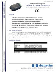
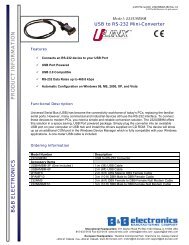
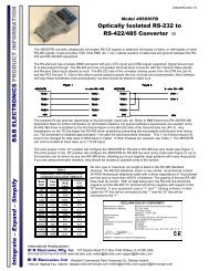
<strong>Industrial</strong> <strong>RS</strong>-<strong>232</strong> <strong>to</strong> <strong>RS</strong>-<strong>422</strong>/<strong>485</strong> Converter<br />
Data Rates up <strong>to</strong> 115.2 Kbps<br />
10 – 48 VDC Input Power Range<br />
Wide Operating Temperature<br />
3-Way 2000V Optical Isolation<br />
Modbus ASCII/RTU Compatible<br />
UL Class 1 Division 2<br />
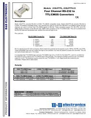
The <strong>Ilinx</strong><strong><strong>485</strong>DRCI</strong> is our premium <strong>Industrial</strong><br />
<strong>RS</strong>-<strong>232</strong> <strong>to</strong> <strong>RS</strong>-<strong>422</strong>/<strong>485</strong> Converter. Designed for<br />
rugged industrial use, it is UL approved and certified<br />
for operation in Class 1 Division 2 environments.<br />
This DIN rail mountable converter optically<br />
isolates and converts unbalanced, full or half-duplex<br />
<strong>RS</strong>-<strong>232</strong> signals <strong>to</strong> balanced <strong>RS</strong>-<strong>422</strong>/<strong>485</strong> signals at<br />
baud rates up <strong>to</strong> 115.2 Kbps. In addition <strong>to</strong> optical<br />
isolation, the unit has surge suppression on the <strong>RS</strong>-<br />
<strong>422</strong>/<strong>485</strong> lines. Featuring Au<strong>to</strong>matic Send Data<br />
Control circuitry, it does not require special software<br />
control of handshake signals in <strong>RS</strong>-<strong>485</strong> mode. The<br />
removable terminal blocks for power and <strong>RS</strong>-<br />
<strong>422</strong>/<strong>485</strong> signals make wiring easy. It is powered by<br />
a supply voltage of 10 <strong>to</strong> 48 VDC which is isolated<br />
from all data and signal ground lines. Configuration<br />
is made easy with a 12 position DIP switch on the<br />
bot<strong>to</strong>m of the converter.<br />
Remember, when it comes <strong>to</strong> reliable<br />
communications in harsh industrial environments,<br />
B&B Electronics’ <strong>Ilinx</strong> brand converters and<br />
isola<strong>to</strong>rs are your number one choice.<br />
Specifications<br />
Serial Technology<br />
TD, RD, GND<br />
Data A(-), Data B (+), GND<br />
TDA(-), TDB(+), RDA (-), RDB(+), GND<br />
DB9 Female (DCE)<br />
Removable Terminal Block, 28 <strong>to</strong> 14 AWG<br />
1.2 <strong>to</strong> 115.2 Kbps<br />
2000 V, 3-Way (Input, Output, Power)<br />
600 W Peak Power Dissipation<br />
Clamping time < 1 pico-second<br />
MODBUS ASCII / RTU<br />
Power<br />
External<br />
10 <strong>to</strong> 48 VDC<br />
960 mW<br />
Removable Terminal Block, 28 <strong>to</strong> 14 AWG<br />
Mechanical<br />
LED Indica<strong>to</strong>rs Transmit, Receive, and Power<br />
Dimensions<br />
4.5 x 1.3 x 4.9 in (11.4 x 3.3 x 12.4 cm)<br />
Enclosure<br />
35mm DIN Mount, Plastic, IP30<br />
Weight 0.45 lbs (204.12 g)<br />
Op TEMP<br />
S<strong>to</strong>rage TEMP<br />
Op Humidity<br />
Environmental<br />
- 40 <strong>to</strong> 176 °F (-40 <strong>to</strong> 80 °C)<br />
- 40 <strong>to</strong> 185 °F (-40 <strong>to</strong> 85 °C)<br />
0 <strong>to</strong> 95% Non-condensing<br />
Regula<strong>to</strong>ry<br />
Approvals FCC, CE, cUL, Class 1 Division 2<br />
UL File Number E222870 (C1 D2 E245458)<br />
MTBF 254617<br />
MTBF Calc. Method Parts Count Reliability Prediction<br />
Type<br />
Size<br />
Temperature<br />
Terminal Torque<br />
<strong><strong>485</strong>DRCI</strong><br />
Accessories<br />
MDR-20-24<br />
Class 1 DIV 2 Wiring<br />
Solid Copper Only<br />
28 <strong>to</strong> 14 AWG<br />
105°C (221 °F) Minimum<br />
0.5 Nm (New<strong>to</strong>n-meters)<br />
Ordering Information<br />
Ind. <strong>RS</strong>-<strong>232</strong> <strong>to</strong> <strong>RS</strong>-<strong>422</strong>/<strong>485</strong> Converter<br />
Ind. 24VDC 1A Slimline Power Supply<br />
International Headquarters: 815-433-5100 Fax 433-5104 www.bb-elec.com<br />
European Headquarters: +353 91 792444 Fax +353 91 792445 www.bb-europe.com
p/n 7207r3 <strong><strong>485</strong>DRCI</strong>-4108ds page 2/5<br />
©2008 B&B Electronics. All rights reserved<br />
Package Contents<br />
DIP Switch (SW1)<br />
B&B ELECTRONICS PRODUCT INFORMATION<br />
• <strong><strong>485</strong>DRCI</strong> <strong>Industrial</strong> <strong>RS</strong>-<strong>232</strong> <strong>to</strong> <strong>RS</strong>-<strong>422</strong>/<strong>485</strong> Converter<br />
• <strong>Datasheet</strong><br />
• Power Terminal Block (installed)<br />
• <strong>RS</strong>-<strong>422</strong>/<strong>485</strong> Terminal Block (installed)<br />
If any item is missing or damaged, contact B&B<br />
Electronics for a replacement<br />
Special Precautions for<br />
Class 1 Div 2 Environment<br />
Special Instructions for Installation and Operation in a<br />
Class 1 DIV 2 Environment.<br />
1. Power, input / output (I/O) wiring must be in accordance<br />
with Class 1 Division 2 wiring methods [Article 501.10(B) of<br />
the National Electrical Code, NFPA70] and in accordance<br />
with the local authority having jurisdiction.<br />
2. WARNING – EXPLOSION HAZARD: SUBSTITUTION<br />
OF COMPONENTS MAY IMPAIR SUITABILITY FOR<br />
CLASS 1, DIVISION 2.<br />
3. WARNING – EXPLOSION HAZARD: WHEN IN<br />
HAZARDOUS LOCATIONS, TURN OFF POWER<br />
BEFORE REPLACING OR WIRING MODULES<br />
4. WARNING – EXPLOSION HAZARD: DO NOT<br />
DISCONNECT EQUIPMENT UNLESS POWER HAS<br />
BEEN SWITCHED OFF OR THE AREA IS KNOWN TO<br />
BE NON-HAZARDOUS.<br />
5. WARNING – THIS APPARATUS IS SUITABLE FOR<br />
USE IN CLASS 1, DIVISION 2, GROUPS A, B, C, AND D,<br />
OR UNCLASSIFIED LOCATIONS.<br />
Front Panel<br />
1 Power TB 2 Position, Removable<br />
2 RD LED Red, Flashes when <strong>RS</strong>-<strong>422</strong>/<strong>485</strong><br />
Data Received<br />
3 DB9 F <strong>RS</strong>-<strong>232</strong> (Wired DCE)<br />
4 <strong>422</strong>/<strong>485</strong> TB 5 Position, Removable<br />
5 TD LED Red Flashes when <strong>RS</strong>-<strong>422</strong>/<strong>485</strong><br />
Data Transmitted<br />
6 Power LED Red, ON When Power Applied<br />
7 Dip Switch 12 Position<br />
Pos ON OFF<br />
1 <strong>RS</strong>-<strong>485</strong> <strong>RS</strong>-<strong>422</strong><br />
2 Half Duplex Full Duplex<br />
3 2-Wire 4-Wire<br />
4 2-Wire 4-Wire<br />
5 Termination In Termination Out<br />
6 TX Bias In TX Bias Out<br />
7 RXBias In RX Bias Out<br />
8 2400 baud<br />
9 4800 baud<br />
10 9600 baud<br />
11 19.2 k baud<br />
12 38.4 k baud<br />
<strong>RS</strong>-<strong>232</strong> DB9F (DCE)<br />
Pin Signal Direction<br />
1 Receive Line Signal Detec<strong>to</strong>r (DCD) ---<br />
2 Receive Data (RD) OUTPUT<br />
3 Transmit Data (TD) INPUT<br />
4 DTE Ready (DTR) ---<br />
5 Signal Ground (SG) ---<br />
6 DCE Ready (DSR) ---<br />
7 Request <strong>to</strong> Send (RTS) ---<br />
8 Clear <strong>to</strong> Send (CTS) ---<br />
9 Ring Indica<strong>to</strong>r (RI) ---<br />
1. DB9 Female Connec<strong>to</strong>r is DCE.<br />
2. Pin 2 (RD) is the Converter’s <strong>RS</strong>-<strong>232</strong> Data Output.<br />
3. Pin 3 (TD) is the Converter’s <strong>RS</strong>-<strong>232</strong> Data Input.<br />
4. Pins 1, 4, and 6 (DCD, DTR, and DSR) are<br />
jumpered <strong>to</strong>gether internally.<br />
5. Pins 7 and 8 (RTS and CTS) are jumpered<br />
<strong>to</strong>gether internally.<br />
International Headquarters: 815-433-5100 Fax 433-5104 www.bb-elec.com<br />
European Headquarters: +353 91 792444 Fax +353 91 792445 www.bb-europe.com
p/n 7207r3 <strong><strong>485</strong>DRCI</strong>-4108ds page 3/5<br />
©2008 B&B Electronics. All rights reserved<br />
B&B ELECTRONICS PRODUCT INFORMATION<br />
<strong>RS</strong>-<strong>422</strong>/<strong>485</strong> Terminal<br />
Block<br />
Terminal <strong>RS</strong>-<strong>485</strong> 2-Wire <strong>RS</strong>-<strong>422</strong>/<strong>485</strong> 4-Wire<br />
A GND GND<br />
B Data B(+) RDB(+)<br />
C Data A(-) RDA(-)<br />
D --- TDB(+)<br />
E --- TDA(-)<br />
DIN Rail Mounting<br />
1. Angle the <strong>to</strong>p portion of the DIN mount over the <strong>to</strong>p of<br />
DIN Rail.<br />
2. Move the converter so that it is parallel with the DIN<br />
Rail.<br />
3. Snap the bot<strong>to</strong>m of the DIN mount in place.<br />
<strong>RS</strong>-<strong>422</strong>/<strong>485</strong> Baud / Timeout<br />
Switch Selectable<br />
Baud SW1 SW1 SW1 SW1 SW1 Timeout<br />
(Kbps) 8 9 10 11 12 (ms)<br />
2.4 ON OFF OFF OFF OFF 4.16<br />
4.8 OFF ON OFF OFF OFF 2.08<br />
9.6 OFF OFF ON OFF OFF 1.04<br />
19.2 OFF OFF OFF ON OFF 0.580<br />
38.4 OFF OFF OFF OFF ON 0.260<br />
Resis<strong>to</strong>r Selectable<br />
Baud<br />
Timeout<br />
(Kbps) SW1-8 through 12 R-11 Value (ms)<br />
1.2 OFF 820 KΩ 8.33<br />
57.6 OFF 16 KΩ 0.176<br />
115.2 OFF 8.2 KΩ 0.087<br />
1. Pre-defined baud rates are set using SW1 positions 8<br />
through 12.<br />
2. Resis<strong>to</strong>r Selectable baud rates are set by inserting a<br />
through-hole resis<strong>to</strong>r (R-11) on the circuit board.<br />
3. WARNING – EXPLOSION HAZARD: SUBSTITUTION<br />
OF COMPONENTS MAY IMPAIR SUITABILITY FOR<br />
CLASS 1, DIVISION 2.<br />
<strong>RS</strong>-<strong>485</strong> 2-Wire<br />
(Half Duplex)<br />
1. Loosen the screws <strong>to</strong> open the TB lead clamps for the<br />
A, B, and C terminals.<br />
2. Insert the <strong>RS</strong>-<strong>485</strong> 2-Wire signal leads. The terminal<br />
board accepts 28 <strong>to</strong> 14 AWG wire.<br />
3. Tighten the screws <strong>to</strong> close the TB lead clamps.<br />
Ensure the clamps hold the leads securely. However,<br />
do not over tighten. For Class 1 DIV 2 installations,<br />
ensure the wiring is in accordance with the special<br />
precautions and the specification table.<br />
4. Configure the DIP Switch on the bot<strong>to</strong>m of the<br />
converter for <strong>RS</strong>-<strong>485</strong> 2-Wire operation (see above).<br />
X. ON = Termination IN<br />
OFF=Termination OUT<br />
Y. ON=TX Bias IN<br />
OFF=TX Bias OUT<br />
Z. ON=RX Bias IN<br />
OFF=RX Bias OUT<br />
Installation Notes:<br />
• In 2-Wire mode, Terminal B is tied <strong>to</strong> Terminal D<br />
and Terminal C is tied <strong>to</strong> Terminal E with DIP<br />
Switch SW1-3 and SW1-4.<br />
• If Termination is required, a 120Ω resis<strong>to</strong>r can be<br />
placed across the D and E terminals by setting<br />
SW1-5 <strong>to</strong> ON.<br />
• This converter has 1.2 KΩ pull-up/down bias<br />
resis<strong>to</strong>rs built in. To use this bias, set SW1-6 and<br />
SW1-7 <strong>to</strong> ON.<br />
• B&B Electronics’ <strong>RS</strong>-<strong>485</strong> Application Note contains<br />
more information about termination and biasing.<br />
This reference is available on our web site.<br />
International Headquarters: 815-433-5100 Fax 433-5104 www.bb-elec.com<br />
European Headquarters: +353 91 792444 Fax +353 91 792445 www.bb-europe.com
p/n 7207r3 <strong><strong>485</strong>DRCI</strong>-4108ds page 4/5<br />
©2008 B&B Electronics. All rights reserved<br />
B&B ELECTRONICS PRODUCT INFORMATION<br />
<strong>RS</strong>-<strong>485</strong> 4-Wire<br />
(Full Duplex)<br />
1. Loosen the screws <strong>to</strong> open the TB lead clamps for the<br />
A, B, C, D, and E terminals.<br />
2. Insert the <strong>RS</strong>-<strong>485</strong> 4-Wire signal leads. The terminal<br />
board accepts 28 <strong>to</strong> 14 AWG wire.<br />
3. Tighten the screws <strong>to</strong> close the TB lead clamps.<br />
Ensure the clamps hold the leads securely. However,<br />
do not over tighten. For Class 1 DIV 2 installations,<br />
ensure the wiring is in accordance with the special<br />
precautions and the specification table.<br />
4. Configure the DIP Switch on the bot<strong>to</strong>m of the<br />
converter for <strong>RS</strong>-<strong>485</strong> 2-Wire operation (see above).<br />
X. ON = Termination IN<br />
OFF=Termination OUT<br />
Y. ON=TX Bias IN<br />
OFF=TX Bias OUT<br />
Z. ON=RX Bias IN<br />
OFF=RX Bias OUT<br />
Installation Notes:<br />
• If Termination is required, a 120Ω resis<strong>to</strong>r can be<br />
placed across the D and E terminals by setting<br />
SW1-5 <strong>to</strong> ON.<br />
• This converter has 1.2 KΩ pull-up/down bias<br />
resis<strong>to</strong>rs built in. To use this bias, set SW1-6 and<br />
SW1-7 <strong>to</strong> ON.<br />
• B&B Electronics’ <strong>RS</strong>-<strong>485</strong> Application Note contains<br />
more information about termination and biasing.<br />
This reference is available on our web site.<br />
<strong>RS</strong>-<strong>422</strong><br />
(Full Duplex)<br />
1. Loosen the screws <strong>to</strong> open the TB lead clamps for the<br />
A, B, C, D, and E terminals.<br />
2. Insert the <strong>RS</strong>-<strong>422</strong> signal leads. The terminal board<br />
accepts 28 <strong>to</strong> 14 AWG wire.<br />
3. Tighten the screws <strong>to</strong> close the TB lead clamps.<br />
Ensure the clamps hold the leads securely. However,<br />
do not over tighten. For Class 1 DIV 2 installations,<br />
ensure the wiring is in accordance with the special<br />
precautions and the specification table.<br />
4. Configure the DIP Switch on the bot<strong>to</strong>m of the<br />
converter for <strong>RS</strong>-<strong>485</strong> 2-Wire operation (see above).<br />
X. ON = Termination IN<br />
OFF=Termination OUT<br />
Y. ON=TX Bias IN<br />
OFF=TX Bias OUT<br />
Z. ON=RX Bias IN<br />
OFF=RX Bias OUT<br />
Installation Notes:<br />
• If Termination is required, a 120Ω resis<strong>to</strong>r can be<br />
placed across the D and E terminals by setting<br />
SW1-5 <strong>to</strong> ON.<br />
• This converter has 1.2 KΩ pull-up/down bias<br />
resis<strong>to</strong>rs built in. To use this bias, set SW1-6 and<br />
SW1-7 <strong>to</strong> ON.<br />
• B&B Electronics’ <strong>RS</strong>-<strong>485</strong> Application Note contains<br />
more information about termination and biasing.<br />
This reference is available on our web site.<br />
International Headquarters: 815-433-5100 Fax 433-5104 www.bb-elec.com<br />
European Headquarters: +353 91 792444 Fax +353 91 792445 www.bb-europe.com
p/n 7207r3 <strong><strong>485</strong>DRCI</strong>-4108ds page 5/5<br />
©2008 B&B Electronics. All rights reserved<br />
Power<br />
Loop Back Test<br />
B&B ELECTRONICS PRODUCT INFORMATION<br />
1. Loosen the screw <strong>to</strong> open the terminal block lead<br />
clamp.<br />
2. Insert the power lead. TB will accept 28 <strong>to</strong> 14AWG<br />
wire.<br />
3. Tighten the screw <strong>to</strong> close the terminal block lead<br />
clamp. Ensure the clamp holds the lead securely.<br />
However, do not over tighten. For Class 1 DIV 2<br />
installations, ensure wiring is in accordance with the<br />
special precautions and specification table.<br />
Mechanical Diagram<br />
1. Configure the converter for <strong>RS</strong>-<strong>485</strong> 4-Wire mode and<br />
the desired baud rate.<br />
2. Place a jumper wire between the B and D terminals<br />
and the C and E terminals.<br />
3. Connect a PC <strong>to</strong> the <strong>RS</strong>-<strong>232</strong> port.<br />
4. Using Hyper Terminal or similar program, connect <strong>to</strong><br />
the appropriate COM port. Set the baud rate <strong>to</strong> match<br />
the converter. Ensure Hyper Terminal local echo is<br />
OFF.<br />
5. Transmit data. If the same data is returned, the test is<br />
good.<br />
International Headquarters: 815-433-5100 Fax 433-5104 www.bb-elec.com<br />
European Headquarters: +353 91 792444 Fax +353 91 792445 www.bb-europe.com