9PFLST - Datasheet - Port-Powered RS-232 Fiber ... - B&B Electronics
9PFLST - Datasheet - Port-Powered RS-232 Fiber ... - B&B Electronics
9PFLST - Datasheet - Port-Powered RS-232 Fiber ... - B&B Electronics

You also want an ePaper? Increase the reach of your titles
YUMPU automatically turns print PDFs into web optimized ePapers that Google loves.
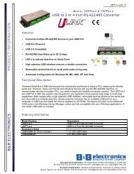
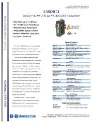
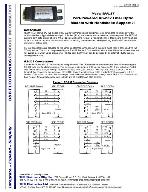
Integrate – Expand – Simplify B&B ELECTRONICS PRODUCT INFORMATIONInternational Headquarters:707 Dayton Road P.O. Box 1040 Ottawa, IL 61350 USA815-433-5100 Fax 433-5104 www.bb-elec.com orders@bb-elec.com support@bb-elec.comWestlink Commercial Park Oranmore Co. Galway Ireland+353 91 792444 Fax +353 91 792445 www.bb-europe.com orders@bb-elec.com support@bb-europe.com<strong>9PFLST</strong>-4303-1/3© 2002 by B&B <strong>Electronics</strong>. All rights reserved.Model <strong>9PFLST</strong><strong>Port</strong>-<strong>Powered</strong> <strong>RS</strong>-<strong>232</strong> <strong>Fiber</strong> OpticModem with Handshake Support CEDescriptionThe <strong>9PFLST</strong> allows any two pieces of <strong>RS</strong>-<strong>232</strong> asynchronous serial equipment to communicate full-duplex over twomulti-mode fibers. Typical distances up to 2.5 miles (4 km) are possible with no external power required. The <strong>9PFLST</strong>supports both data signals at up to 115.2 kbps as well as the RTS/CTS handshake lines. This means the <strong>9PFLST</strong> canreplace short haul modems and isolators when connecting remote devices, while providing the EMI/RFI and transientimmunity of optical fiber.<strong>RS</strong>-<strong>232</strong> connections are provided on the same DB9 female connector, while the multi-mode fiber is connected via twoST connectors. The unit is port powered by the <strong>RS</strong>-<strong>232</strong> Transmit Data and handshake lines. When handshake lines arenot available, or when using a low power <strong>RS</strong>-<strong>232</strong> port, the <strong>9PFLST</strong> can be powered by an external 12VDC supply,drawing 50 mA max.<strong>RS</strong>-<strong>232</strong> ConnectionsConnection of the <strong>9PFLST</strong> is simple and straightforward. The DB9 female serial connector is used for connecting the<strong>RS</strong>-<strong>232</strong> data and handshake signals. The connector is pinned as a DCE device (input on Pin 3 and output on Pin 2.)This means that a straight through cable can be used from your DB9 port from any DTE device such as a PC orterminal. For connecting to modems or other DCE devices, a null modem cable or adapter that swaps pins 2 & 3 isneeded. Care should be taken that any output handshake lines be connected through to the <strong>9PFLST</strong> to power the unit.See Figure 1 for connection diagrams to 9 pin and 25 pin DTE and DCE devices.DB25 DTE Device234520687DB9 DTE Device32784615TDRDRTSCTSDT<strong>RS</strong>ignal GNDTDRDRTSCTSDT<strong>RS</strong>ignal GNDFigure 1: <strong>RS</strong>-<strong>232</strong> Connection Diagrams<strong>9PFLST</strong> DB9327845POWER<strong>9PFLST</strong> DB932784POWER5DB25 DCE Device234520687DB9 DCE Device32784615TDRDRTSCTSDSRorDCDSignal GNDTDRDRTSCTSDSRorDCDSignal GND 5<strong>9PFLST</strong> DB92 (RD)3 (TD)8 (CTS)7 (RTS)POWER4 (DTR)5<strong>9PFLST</strong> DB92 (RD)3 (TD)8 (CTS)7 (RTS)POWER4 (DTR)
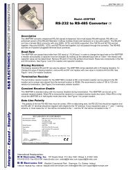
Integrate – Expand – Simplify B&B ELECTRONICS PRODUCT INFORMATIONInternational Headquarters:707 Dayton Road P.O. Box 1040 Ottawa, IL 61350 USA815-433-5100 Fax 433-5104 www.bb-elec.com orders@bb-elec.com support@bb-elec.comWestlink Commercial Park Oranmore Co. Galway Ireland+353 91 792444 Fax +353 91 792445 www.bb-europe.com orders@bb-elec.com support@bb-europe.com<strong>9PFLST</strong>-4303-2/3© 2002 by B&B <strong>Electronics</strong>. All rights reserved.<strong>Fiber</strong> Optic ConnectionsThe <strong>9PFLST</strong> uses a separate LED emitter and photo-detector operating at 820 nm wavelength. Connections to theemitter and detector are on ST type connectors. Almost any multi-mode glass fiber size can be used including 50/125µm, 62.5/125 µm, 100/140 µm, and 200 µm. Two fibers are required between the two modems, one for data in eachdirection.The most important consideration in planning the fiber optic link is the “power budget” of the fiber modem. This valuetells you the amount of loss in dB that can be present in the link between the two modems before the units fail toperform properly. This value will include line attenuation as well as connector loss. For the <strong>9PFLST</strong> the typicalconnector-to-connector power budget is 12.1 dB. Because 62.5/125 µm cable typically has a line attenuation of 3 dBper km at 820 nm, the 12.1 dB power budget translates into 2.5 miles (4 km). This assumes no extra connectors orsplices in the link. Each extra connection would typically add 0.5 dB of loss, reducing the possible distance by 166 m(547 ft.) Your actual loss should be measured before assuming distances. When the <strong>9PFLST</strong> is used without externalpower, the power available to the <strong>Fiber</strong> Optic transmitter may be less than the typical value. The link should be testedwith the <strong>9PFLST</strong> in place with a variable attenuator to check the optical power budget of the whole system.<strong>RS</strong>-<strong>232</strong>DEVICESpecificationsTransmission Line:Transmission Mode:Interface:Signals:Data Rates:Typical Range:Coupled Power Budget:Optic Wavelength:Connectors:Power Supply:Optional External Power Supply:Dimensions:DECLARATION OF CONFORMITYManufacturer’s Name:B&B <strong>Electronics</strong> Manufacturing CompanyManufacturer’s Address: P.O. Box 1040707 Dayton RoadOttawa, IL 61350 USAModel Number:<strong>9PFLST</strong>Description:<strong>Port</strong>-<strong>Powered</strong> <strong>Fiber</strong> Optic ModemType:Light industrial ITE equipmentApplication of Council Directive: 89/336/EECStandards: EN 55022EN 61000-6-1EN 61000 (-4-2, -4-3, -4-4, -4-5, -4-6, -4-8, -4-11)William H. Franklin III, Director of Engineering<strong>9PFLST</strong>TXRXFigure 2: Typical SetupDuplexMultimode<strong>Fiber</strong>RXDual multi-mode optical cableAsynchronous, half or full-duplex, point-to-point<strong>RS</strong>-<strong>232</strong>Transmit Data, Receive Data, Request to Send, Clear to Send0 to 115.2 kbpsUp to 2.5 miles (4 km) on multi-mode glass fiber12.1 dB820 nmDB9 Female for serial connection, ST Connectors for fiber<strong>Port</strong> <strong>Powered</strong> from Transmit Data, RTS, and DTR lines10 – 16 VDC @ 50 mA max.4.3 x 1.7 x 1.0 in (10.9 x 4.3 x 2.4 cm)TX<strong>9PFLST</strong><strong>RS</strong>-<strong>232</strong>DEVICE
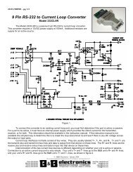
Integrate – Expand – Simplify B&B ELECTRONICS PRODUCT INFORMATIONFigure 3: <strong>9PFLST</strong> Circuit DiagramInternational Headquarters:707 Dayton Road P.O. Box 1040 Ottawa, IL 61350 USA815-433-5100 Fax 433-5104 www.bb-elec.com orders@bb-elec.com support@bb-elec.comWestlink Commercial Park Oranmore Co. Galway Ireland+353 91 792444 Fax +353 91 792445 www.bb-europe.com orders@bb-elec.com support@bb-europe.com<strong>9PFLST</strong>-4303-3/3© 2002 by B&B <strong>Electronics</strong>. All rights reserved.