Vulcraft Steel Joists and Joist Girders Catalog - Sites at Lafayette
Vulcraft Steel Joists and Joist Girders Catalog - Sites at Lafayette
Vulcraft Steel Joists and Joist Girders Catalog - Sites at Lafayette

Create successful ePaper yourself
Turn your PDF publications into a flip-book with our unique Google optimized e-Paper software.
TABLE OF CONTENTS<br />
**IMPORTANT NOTICE**<br />
BASED UPON FINDINGS OF INDUSTRY<br />
SPONSORED RESEARCH, THE STEEL<br />
J O I S T INSTITUTE HAS DEVELOPED<br />
NEW REQUIREMENTS FOR THE USE<br />
OF ERECTION STA B I L I T Y BRIDGING.<br />
THE NEW SJI SPECIFICATIONS<br />
REQUIRE BOLTED DIAGONAL<br />
BRIDGING TO BE INSTALLED FOR<br />
SOME K-SERIES AND LH-SERIES<br />
JOISTS BEFORE SLACKENING T H E<br />
HOISTING LINES. THE JOIST S PA N S<br />
REQUIRING THIS STA B I L I T Y B R I D G I N G<br />
ARE SHADED IN THE LOAD TABLES.<br />
I T IS VERY I M P O RTA N T FOR JOIST<br />
SPECIFIERS AND ERECTORS TO<br />
KNOW T H AT O S H A IS INTERPRETING<br />
29CFR-1926.751 (c)2 TO MEAN A L L<br />
J O I S T F O RT Y (40) FEET (12192MM)<br />
AND LONGER TO REQUIRE A ROW OF<br />
B O LTED BRIDGING TO BE IN PLACE<br />
BEFORE SLACKENING OF HOISTING<br />
LINES.<br />
VULCRAFT DESIGN NOTICE . . . . . . . . . . . . .3<br />
GENERAL INFORMATION . . . . . . . . . . . . . . .6<br />
A. <strong>Joist</strong> Design Commentary<br />
1. Vibr<strong>at</strong>ion<br />
2. Deflection<br />
3. How to Specify Concentr<strong>at</strong>ed &<br />
Other Non-Uniform Loads on <strong>Steel</strong> <strong><strong>Joist</strong>s</strong><br />
LOAD RESISTANCE FACTOR DESIGN . . . . .8<br />
K AND KCS SERIES . . . . . . . . . . . . . . . . . . . .9<br />
A. General Inform<strong>at</strong>ion<br />
B. K-U.S. Customary Load Tables<br />
C. KCS Load Tables (U.S. <strong>and</strong> Metric)<br />
D. K-Metric Load Tables<br />
E. K-Specific<strong>at</strong>ions<br />
ACCESSORIES AND DETAILS . . . . . . . . . . .31<br />
A. VS Series <strong>and</strong> Loose Outriggers<br />
B. K-Details<br />
C. LH <strong>and</strong> DLH-Details<br />
LH AND DLH SERIES . . . . . . . . . . . . . . . . . .43<br />
A. General Inform<strong>at</strong>ion<br />
B. LH-U.S. Customary Load Tables<br />
C. DLH-U.S. Customary Load Tables<br />
D. LH-Metric Load Tables<br />
E. DLH-Metric Load Tables<br />
F. LH <strong>and</strong> DLH Specific<strong>at</strong>ions<br />
SLH SERIES . . . . . . . . . . . . . . . . . . . . . . . . .63<br />
A. General Inform<strong>at</strong>ion<br />
B. SLH Details<br />
C. SLH-Load Tables<br />
D. SLH-Specific<strong>at</strong>ions<br />
JOIST GIRDERS . . . . . . . . . . . . . . . . . . . . . .74<br />
A. General Inform<strong>at</strong>ion<br />
B. <strong>Joist</strong> Girder Details<br />
C. Bottom Chord Brace Tables<br />
D. <strong>Joist</strong> <strong>Girders</strong> in Moment Resistant Frames<br />
E. <strong>Joist</strong> Girder Weight Table-U.S. Customary<br />
F. <strong>Joist</strong> Girder Weight Table-Metric<br />
G. <strong>Joist</strong> Glrder Specific<strong>at</strong>ions<br />
FIRE RESISTANCE RATINGS WITH<br />
STEEL JOIST AND JOIST GIRDERS . . . . .103<br />
ECONOMICAL JOIST GUIDE . . . . . . . . . . .107<br />
RECOMMENDED CODE<br />
OF STANDARD PRACTICE . . . . . . . . . . . . .119<br />
PUBLICATIONS . . . . . . . . . . . . . . . . . . . . .127<br />
FRONT COVER PICTURE:<br />
Brown & Root Employee Center<br />
Houston, Texas<br />
General Contractor: Brown & Root<br />
<strong>Steel</strong> Fabric<strong>at</strong>or: Palmer <strong>Steel</strong> Supplies, Inc.<br />
1
1995 REVISIONS<br />
PAGE SECTION CHANGE<br />
1 Added notice regarding bridging.<br />
6 Vibr<strong>at</strong>ion Revised.<br />
7 Concentr<strong>at</strong>ed Loads Revised.<br />
8 LRFD Added.<br />
9 K-Series New bridging tables.<br />
10-13 K-Series Added shading <strong>and</strong> OSHA note for erection stability requirement.<br />
14-17 KCS-Series Change from CS-Series, added metric.<br />
18-21 K-Series Added metric load tables.<br />
22-29 K-Series Revised specific<strong>at</strong>ions to include metric <strong>and</strong> new bridging criteria.<br />
31 Accessories & Details Revised VS-Series.<br />
35-36 Accessories & Details New bridging requirements.<br />
39 Accessories & Details New top chord extension load table-metric.<br />
40 Accessories & Details Revised camber tables to include metric.<br />
43 LH-DLH Series New bridging tables.<br />
44-46 LH-Series Added shading <strong>and</strong> OSHA note for erection stability requirement.<br />
47-48 DLH-Series Added shading for erection stability requirement.<br />
49-52 LH-Series New metric tables.<br />
53-54 DLH-Series New metric tables.<br />
55-62 LH-DLH Series Revised specific<strong>at</strong>ions to include metric <strong>and</strong> new bridging criteria.<br />
77 <strong>Joist</strong> <strong>Girders</strong> Re-worded.<br />
78 <strong>Joist</strong> <strong>Girders</strong> Added detail "F".<br />
80-88 <strong>Joist</strong> <strong>Girders</strong> Enhanced weight tables <strong>and</strong> added stepped line to indic<strong>at</strong>e when<br />
a 10 inch deep bearing should be used.<br />
89-95 <strong>Joist</strong> <strong>Girders</strong> New metric design example <strong>and</strong> metric weight tables.<br />
96-102 <strong>Joist</strong> <strong>Girders</strong> Revised specific<strong>at</strong>ions to include metric.<br />
103-106 Fire Resistance R<strong>at</strong>ings Revised stress limit<strong>at</strong>ions <strong>and</strong> revised some fire resistance r<strong>at</strong>ings.<br />
107-118 Economical <strong>Joist</strong> Guide Added shading for erection stability requirements. Method of listing<br />
joists in order of economies has been revised.<br />
119-126 Recommended Code<br />
of St<strong>and</strong>ard Practice<br />
Revised to include metric <strong>and</strong> new bridging criteria.<br />
2
A WORD ABOUT QUALITY<br />
In manufacturing steel joists, there can be no compromise<br />
on quality. Your business depends on it. Our reput<strong>at</strong>ion<br />
<strong>and</strong> success depends on it. As the largest<br />
manufacturer of steel joists in the United St<strong>at</strong>es, a lot<br />
of buildings <strong>and</strong> a lot of people depend on <strong>Vulcraft</strong> for<br />
consistently high st<strong>and</strong>ards of quality th<strong>at</strong> are demonstr<strong>at</strong>ed<br />
in reliable performance.<br />
In the manufacturing of steel joists <strong>and</strong> joist girders,<br />
<strong>Vulcraft</strong> uses high quality steel. Welding to exact specific<strong>at</strong>ions<br />
is the key to making structurally sound joists-<br />
-<strong>and</strong> the most critical step in the entire process. This<br />
being the case, all <strong>Vulcraft</strong> welders are certified to<br />
American Welding Society st<strong>and</strong>ards. All welds are in<br />
accordance with the <strong>Steel</strong> <strong>Joist</strong> Institute’s welding criteria<br />
<strong>and</strong> all <strong>Vulcraft</strong> joists are manufactured to meet<br />
the required design loads of the specifying professional.<br />
To further insure the precision <strong>and</strong> quality of every<br />
weld, every <strong>Vulcraft</strong> quality assurance inspector is also<br />
certified to these same high st<strong>and</strong>ards. Furthermore<br />
<strong>Vulcraft</strong>’s quality assurance supervisors report directly<br />
to the engineering manager. <strong>Vulcraft</strong> also employs an<br />
ongoing program of mechanical testing th<strong>at</strong> includes<br />
full scale load tests <strong>at</strong> every facility.<br />
As the leading manufacturer of steel joists <strong>and</strong> joist<br />
girders in the United St<strong>at</strong>es, Vu l c r a f t ’s reput<strong>at</strong>ion<br />
depends on successfully managed quality control programs.<br />
Th<strong>at</strong>’s why quality is important <strong>at</strong> <strong>Vulcraft</strong>. You<br />
have our word on it.<br />
NOTICE<br />
<strong>Vulcraft</strong>, a Division of Nucor Corpor<strong>at</strong>ion, has provided<br />
this c<strong>at</strong>alog for use by engineers <strong>and</strong> architects in<br />
designing <strong>and</strong> using <strong>Vulcraft</strong> open web joists <strong>and</strong> open<br />
web girders. It includes all products available <strong>at</strong> the<br />
time of printing. <strong>Vulcraft</strong> reserves the right to change,<br />
revise or withdraw any Products or procedures without<br />
notice.<br />
The inform<strong>at</strong>ion presented in this c<strong>at</strong>alog has been<br />
prepared in accordance with recognized engineering<br />
principles <strong>and</strong> is for general inform<strong>at</strong>ion only. While it<br />
is believed to be accur<strong>at</strong>e, this inform<strong>at</strong>ion should not<br />
be used or relied upon for any specific applic<strong>at</strong>ion without<br />
competent professional examin<strong>at</strong>ion <strong>and</strong> verific<strong>at</strong>ion<br />
of its accuracy, suitability <strong>and</strong> applicability by an<br />
engineer, architect or other licensed professional.<br />
<strong>Vulcraft</strong> is a manufacturer of open web steel joists, joist<br />
girders, floor deck <strong>and</strong> roof deck. <strong>Vulcraft</strong> employs a<br />
staff of engineers for the design, manufacture <strong>and</strong><br />
marketing of its products. <strong>Vulcraft</strong> does not accept the<br />
responsibility as the design professional of record for<br />
any structure. <strong>Vulcraft</strong> accepts the deleg<strong>at</strong>ion of the<br />
engineering responsibility only for the products it manufactures,<br />
provided the applic<strong>at</strong>ion <strong>and</strong> applicable<br />
loading for these products are specified by the design<br />
professional of record. <strong>Vulcraft</strong> provides engineering<br />
for the design of its products <strong>and</strong> does not displace the<br />
need on any project for a design professional of<br />
record.<br />
3
VULCRAFT<br />
STEEL JOISTS AND JOIST GIRDERS,<br />
STEEL ROOF AND FLOOR DECK,<br />
COMPOSITE JOISTS<br />
VULCRAFT OFFERS A WIDE RANGE OF<br />
JOISTS, JOIST GIRDERS AND DECK PRODUCTS.<br />
FOR MORE INFORMATION,<br />
CONTACT A VULCRAFT SALES OFFICE<br />
VULCRAFT<br />
MANUFACTURING LOCATIONS:<br />
P.O. Box 637 Brigham City, UT 84302* (435) 734-9433 Fax: (435) 732-5423<br />
P.O. Box 100520 Florence, SC 29501 (843) 662-0381 Fax: (843) 662-3132<br />
P.O. Box 680169 Fort Payne, AL 35968 (256) 845-2460 Fax: (256) 845-2823<br />
P.O. Box 186 Grapel<strong>and</strong>, TX 75844 (936) 687-4665 Fax: (936) 687-4290<br />
P.O. Box 59 Norfolk, NE 68702 (402) 644-8500 Fax: (402) 644-8528<br />
P.O. Box 1000 St. Joe, IN 46785 (219) 337-1800 Fax: (219) 337-1801<br />
P.O. Box 280 Chemung, NY 14825 (607) 529-9000 Fax: (607) 529-9001<br />
*STEEL JOISTS, JOIST GRIDERS AND COMPOSITE JOISTS ONLY.<br />
www.vulcraft.com<br />
312 Elm Building, Cincinn<strong>at</strong>i, Ohio<br />
Architect: Space Design Intern<strong>at</strong>ional<br />
Structural Engineer: Stanley D. Lindsey <strong>and</strong> Associ<strong>at</strong>es<br />
Developer: Duke Construction Management<br />
<strong>Steel</strong> Fabric<strong>at</strong>ors: Ferguson <strong>Steel</strong><br />
<strong>Steel</strong> Erector: Ben Hur Construction<br />
4
ALABAMA<br />
P.O. Box 680169, Fort Payne, Alabama 35968 (256) 845-2460<br />
<strong><strong>Joist</strong>s</strong> & Deck Fax: (256) 845-2823<br />
INDIANA<br />
P.O. Box 1000, St. Joe, Indiana 46785 (219) 337-1800<br />
<strong><strong>Joist</strong>s</strong> & Deck Fax: (219) 337-1801<br />
NEBRASKA<br />
P.O. Box 59, Norfolk, Nebraska 68702 (402) 644-8500<br />
<strong><strong>Joist</strong>s</strong> & Deck Fax: (402) 644-8528<br />
SOUTH CAROLINA<br />
P.O. Box 100520, Florence, South Carolina 29501 (843) 662-0381<br />
<strong><strong>Joist</strong>s</strong> & Deck Fax: (843) 662-3132<br />
TEXAS<br />
P.O.Box 186, Grapel<strong>and</strong>, Texas 75844 (936) 687-4665<br />
<strong><strong>Joist</strong>s</strong> & Deck Fax: (936) 687-4290<br />
UTAH<br />
P.O. Box 637, Brigham City, Utah 84302 (435) 734-9433<br />
<strong><strong>Joist</strong>s</strong> Fax: (435)723-5423<br />
Coming By Fall 2001 <strong>Vulcraft</strong> of New York<br />
5
JOINT DESIGN COMMENTARY<br />
FLOOR VIBRATION<br />
Floor vibr<strong>at</strong>ion occurs, in varying degrees, in all types<br />
of building construction. Unlike steady st<strong>at</strong>e vibr<strong>at</strong>ion,<br />
which can be isol<strong>at</strong>ed, vibr<strong>at</strong>ion due to human impact<br />
is inconsistent in amplitude <strong>and</strong> frequency <strong>and</strong> therefore,<br />
more difficult to control.<br />
The <strong>Steel</strong> <strong>Joist</strong> Institute has studied this phenomenon<br />
for many years. Labor<strong>at</strong>ory research has been performed<br />
<strong>and</strong> numerous buildings, exhibiting both good<br />
<strong>and</strong> bad characteristics, were tested using seismic<br />
recording instruments. The findings have been published<br />
by the SJI in Technical Digest #5.<br />
The vast majority of structures, including those utilizing<br />
steel joists, do not exhibit floor vibr<strong>at</strong>ions severe<br />
enough to be considered objectionable. However,<br />
human sensitivity to vibr<strong>at</strong>ory motion varies, <strong>and</strong> a s<strong>at</strong>isfactory<br />
framing solution is dependent upon the sound<br />
judgement of qualified structural engineers.<br />
The following observ<strong>at</strong>ions are in keeping with the<br />
research d<strong>at</strong>a for vibr<strong>at</strong>ional characteristics not objectionable<br />
to normal human response, <strong>and</strong> are recommended<br />
only as a guide.<br />
DEFINITIONS<br />
Floor vibr<strong>at</strong>ion is measured in terms of amplitude <strong>and</strong><br />
frequency. These two factors are not objectionable to<br />
all people <strong>at</strong> the same level since human sensitivity<br />
varies.<br />
Amplitude is defined as the magnitude or total distance<br />
traveled by each oscill<strong>at</strong>ion of the vibr<strong>at</strong>ion.<br />
Frequency is the term used to describe the speed of<br />
the oscill<strong>at</strong>ions <strong>and</strong> is expressed in cycles per second<br />
or Hz.<br />
Acceler<strong>at</strong>ion results from combining amplitude <strong>and</strong><br />
frequency <strong>and</strong> is the only vibr<strong>at</strong>ion factor which<br />
humans can sense.<br />
Damping is defined as the r<strong>at</strong>e of decay of amplitude.<br />
OPEN FLOOR AREAS are most subject to vibr<strong>at</strong>ional<br />
problems. Objections occur most often when a 2 l/2"<br />
thick slab of lightweight concrete is used on spans in<br />
the range of 28 feet. As the spans both increase <strong>and</strong><br />
decrease from this length, the likelihood of objectionable<br />
vibr<strong>at</strong>ion tends to taper off. Partitions, file cabinets,<br />
book stacks, heavy furnishings <strong>and</strong> even crowds<br />
of people provide additional damping <strong>and</strong> minimize<br />
complaints.<br />
THICKER FLOOR SLABS are an economical solution<br />
to floor vibr<strong>at</strong>ion, when open floor areas are required.<br />
Additional thickness increases floor system stiffness<br />
transverse to the joists, thus reducing the amplitude. A<br />
slight increase in frequency will be offset by the additional<br />
mass of the system, producing a reduction of<br />
objectionable vibr<strong>at</strong>ion.<br />
WIDER JOIST SPACINGS improve vibr<strong>at</strong>ional characteristics<br />
only when combined with thicker floor slabs.<br />
The resulting increase in joist size does not contribute<br />
significantly to the composite section. When used with<br />
a thicker slab, gre<strong>at</strong>er resistance to vibr<strong>at</strong>ion can be<br />
achieved, <strong>and</strong>, since fewer pieces must be installed,<br />
may be more economical.<br />
PARTITIONS introduce damping <strong>and</strong> usually elimin<strong>at</strong>e<br />
vibr<strong>at</strong>ion problems. They will be effective either above<br />
or below a floor. Partitions below provide damping<br />
even though only <strong>at</strong>tached to suspended ceilings <strong>and</strong><br />
not in direct contact with joists.<br />
S U P P O RT FRAMING BEAMS sometimes gre<strong>at</strong>ly<br />
magnify floor vibr<strong>at</strong>ion. If a floor vibr<strong>at</strong>ion problem is<br />
judged to be imminent, one needs to calcul<strong>at</strong>e the n<strong>at</strong>ural<br />
frequency <strong>and</strong> amplitude for both the joist <strong>and</strong><br />
supporting joist girders or beams. In this manner the<br />
resulting system amplitude <strong>and</strong> frequency can be<br />
determined from which the required system damping<br />
can be calcul<strong>at</strong>ed. The damping provided in the system<br />
should be gre<strong>at</strong>er than the calcul<strong>at</strong>ed required<br />
damping.<br />
INCREASING JOIST STIFFNESS above th<strong>at</strong> which is<br />
required by live load deflection is not a good solution.<br />
Increasing the stiffness of the steel joists themselves<br />
results in increasing the frequency <strong>and</strong> slightly<br />
decreasing the amplitude of the floor vibr<strong>at</strong>ion.<br />
BRIDGING of all st<strong>and</strong>ard types provide equal floor<br />
vibr<strong>at</strong>ional characteristics.<br />
LONGER FLOOR SPANS have many advantages<br />
over shorter spans, both in construction cost <strong>and</strong> in<br />
vibr<strong>at</strong>ional response. Floor spans over 40 feet with a<br />
2-1/2" thick concrete slab give a vibr<strong>at</strong>ional frequency<br />
in the 3-5 cycles per second range. A human can toler<strong>at</strong>e<br />
a larger amplitude <strong>at</strong> this reduced frequency<br />
without sensing it. Thus, there is minimal sens<strong>at</strong>ion of<br />
motion <strong>and</strong> the floor feels extremely stable.<br />
ASSISTANCE can be given to architects <strong>and</strong> engineers<br />
on the subject of vibr<strong>at</strong>ion <strong>and</strong> steel joist construction.<br />
Call the engineering manager <strong>at</strong> the nearest<br />
<strong>Vulcraft</strong> manufacturing facility.<br />
PC based software to evalu<strong>at</strong>e vibr<strong>at</strong>ion of joist supported<br />
floor systems is available from the STEEL<br />
JOIST INSTITUTE, 3127 10 th Ave. North Ext., Myrtle<br />
Beach, SC 29577, phone (843) 626-1995 <strong>and</strong><br />
S T R U C T U R A L ENGINEERS, INC., 537 Wi s t e r i a<br />
Drive, Radford, VA 24141, Fax no. (703) 731-3330.<br />
CONCLUSIONS:<br />
Partitions elimin<strong>at</strong>e vibr<strong>at</strong>ion problems. When a floor<br />
area cannot have partitions, increasing the slab thickness<br />
is the most economical <strong>and</strong> effective way to prevent<br />
vibr<strong>at</strong>ion objections. <strong>Steel</strong> joist <strong>and</strong> concrete slab<br />
open floor areas have generally not given objectionable<br />
vibr<strong>at</strong>ion <strong>at</strong> spans less than 20 feet or gre<strong>at</strong>er<br />
than 40 feet even with only 2 l/2" slab. Due consider<strong>at</strong>ion<br />
should also be given to support framing beams as<br />
outlined above.<br />
For more inform<strong>at</strong>ion refer to <strong>Steel</strong> <strong>Joist</strong> Institute Technical Digest<br />
No. 5 "Vibr<strong>at</strong>ion of <strong>Steel</strong> <strong>Joist</strong>-Concrete Slab Floors."<br />
6
JOINT DESIGN COMMENTARY<br />
DEFLECTION OF STEEL JOISTS<br />
The deflection of a steel joist when loaded with a<br />
uniformly-distributed load depends upon the following<br />
factors:<br />
w= uniformly-distributed load carried by the joist (plf)<br />
L= (span of the joist -.33)(ft.)<br />
E= modulus of elasticity of steel (29,000,000 psi)<br />
I= 26.767 WLL (L3) (10 -6 ) where WLL=red figure in<br />
load table<br />
Tests have shown th<strong>at</strong> deflection <strong>at</strong> mid-span may<br />
be determined with reasonable accuracy using the<br />
following formula:<br />
Deflection (inches)=<br />
1.15x5wL 4 (12 3 ) =<br />
384El<br />
25.88wL 4<br />
E l<br />
Example: Determine the approxim<strong>at</strong>e total load deflection<br />
of a 24K8 for the following conditions:<br />
W=280 plf L=40.0 ft<br />
W LL = 161 plf E=29,000,000 psi<br />
I=26.767(161) (40-.33) 3 (10 -6 )= 269.0 in. 4<br />
Deflection=<br />
25.88(280)(40-.33) 4 =2.30 in.<br />
29,000,000(269)<br />
HOW TO SPECIFY CONCENTRATED AND OTHER<br />
NON-UNIFORM LOADS ON STEEL JOISTS<br />
K-SERIES<br />
When working with K-series joists, the specifying professional<br />
has two means by which to h<strong>and</strong>le concentr<strong>at</strong>ed<br />
loads. First, KCS joists may be chosen (see<br />
page 14). These new SJI joists are specifically<br />
designed to address the problems cre<strong>at</strong>ed by non-uniform<br />
loading <strong>and</strong> using KCS joists is the best altern<strong>at</strong>ive<br />
for a loading condition th<strong>at</strong> cannot be loc<strong>at</strong>ed<br />
during the design phase.<br />
Second, the design loads can be shown on the contract<br />
drawings. If this method is used all concentr<strong>at</strong>ed<br />
loads must be loc<strong>at</strong>ed <strong>and</strong> the magnitude of the loads<br />
must be given <strong>and</strong> any other non-uniform loading must<br />
include the loc<strong>at</strong>ion <strong>and</strong> magnitude. The best way to<br />
h<strong>and</strong>le this is through a load diagram. The specifying<br />
professional must specifically instruct the joist manufacturer<br />
to provide special joists for these situ<strong>at</strong>ions.<br />
These joists are to be labeled "SP" on the plan. A<br />
NOTE OF CAUTION IS DUE HERE. In no case should<br />
the required resisting moment or end reaction exceed<br />
the highest values tabul<strong>at</strong>ed for the KCS joists of the<br />
specified depth. Those values represent the practical<br />
upper limits for the respective joist depths.<br />
The <strong>Steel</strong> <strong>Joist</strong> Institute has an example for each of<br />
these choices. They are reprinted in this c<strong>at</strong>alog on<br />
page 14 for the KCS example <strong>and</strong> on page 124 for the<br />
special (SP) design example.<br />
Wh<strong>at</strong>ever option is chosen, it is still possible the<br />
required shear <strong>and</strong>/or moment exceeds th<strong>at</strong> which can<br />
be developed with a K-series joist. In the event this<br />
happens, the specifying professional can do one of<br />
two things:<br />
1) Use double joists. Both joists would be KCS joists<br />
or "specials" (SP), but carrying half of the required<br />
loads.<br />
2) Specifying a special (SP) LH-series joist. (NOTE:<br />
LH joists require deeper bearing se<strong>at</strong>s.)<br />
LH-SERIES<br />
When it is necessary for LH-series joists to be specified<br />
to support concentr<strong>at</strong>ed loads, the specifying professional<br />
should provide the design requirements for<br />
these joists on the structural drawings. This must be<br />
done by giving both the uniform load <strong>and</strong> any non-uniform<br />
loads. If the non-uniform loads are concentr<strong>at</strong>ed<br />
the loc<strong>at</strong>ion <strong>and</strong> magnitude of each load must be provided.<br />
A load diagram of each joist should be provided.<br />
A specific note instructing the joist manufacturer to<br />
design a special (SP) joist should be given.<br />
Regardless of whether K-series, KCS-series or LHseries<br />
joists are specified, it is important to note th<strong>at</strong><br />
even though sufficient shear <strong>and</strong> moment capacity are<br />
provided within the special joist, the localized bending<br />
of the chord members due to concentr<strong>at</strong>ed loading<br />
between panel points is not considered. The joist<br />
design generally presumes th<strong>at</strong> all concentr<strong>at</strong>ed loads<br />
are to be applied <strong>at</strong> panel points. When this is not the<br />
case, the specifying professional must specify on the<br />
structural drawings of the contract documents one of<br />
the following methods:<br />
1) A field installed member be loc<strong>at</strong>ed <strong>at</strong> all concentr<strong>at</strong>ed<br />
loads not occurring <strong>at</strong> panel points (see<br />
detail C1).<br />
2) The magnitude <strong>and</strong> loc<strong>at</strong>ions of all loads can be<br />
provided on the structural drawings <strong>and</strong> <strong>Vulcraft</strong><br />
can shop install an additional web, thus elimin<strong>at</strong>ing<br />
the field labor.<br />
The second altern<strong>at</strong>ive is the most economical.<br />
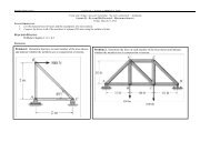
DETAIL C1<br />
VARYING UNIFORM LOADS ON STEEL JOISTS<br />
The selection process of a joist for varying uniform<br />
loads such as drift loads or stepped uniform loads is<br />
essentially the same as th<strong>at</strong> for concentr<strong>at</strong>ed loads.<br />
For K-series joists where the uniform load exceeds<br />
550 pounds per lineal foot, the only options are: double<br />
joists or the use of special (SP) joists. Again a load<br />
diagram should be shown on the structural drawings.<br />
7
L O A DA N D R E S I S TANCE FACTOR DESIGN<br />
The following method may be used to convert the <strong>Steel</strong> <strong>Joist</strong><br />
I n s t i t u t e ’s Specific<strong>at</strong>ions for use in Load <strong>and</strong> Resistance<br />
Factor Design ( LRFD )<br />
M e t h o d :<br />
WU = 1.65 Wsji, or Wsji = WU /1.65<br />
W h e r e , WU = ultim<strong>at</strong>e joist capacity<br />
Wsji = SJI Load Table Load (black figure)<br />
Load tables for LRFD can be obtained directly from the current SJI Load Tables by using the formula:<br />
Wn = Wsji x 0.9 x 1.65<br />
W h e r e , Wn = nominal joist capacity<br />
0.9 = Resistance Factor ( 0 )<br />
“K” Series Example:<br />
Given: WU = 1.2 WD + 1.6 WL<br />
Problem: Select a joist from the current load tables for Wsji ≥ Wu/1.65( 0 )<br />
L = 40 ft.<br />
WD = 50 plf<br />
W L = 150 plf<br />
Use Roof Live load deflection ≤ L/240<br />
WU = 1.2 x 50 + 1.6 x 150 = 300 plf<br />
Wsji ≥ 300/(1.65 x 0.9) = 202 plf<br />
Select 22K6: Wsji @ 40 ft. span = 207 plf > 202 plf. O’K’<br />
Deflection Live Load ≤ L/240<br />
W s j i L L = 1.5 x 111 = 166 plf > 150 plf O’K’<br />
The above procedure outlines the specific<strong>at</strong>ion of a “K” Series <strong>Joist</strong> to support a uniform gravity load utilizing<br />
LRFD. When loads other than uniform gravity loads (such as wind uplift loads, concentr<strong>at</strong>ed loads, end<br />
moments or non-uniform loads) are a design consider<strong>at</strong>ion, the Specifying Professional shall clearly indic<strong>at</strong>e on<br />
the structural drawings whether these loads are factored or unfactored. To remain consistent with established<br />
LRFD design procedures it is recommended th<strong>at</strong> factored loads be specified.<br />
The above procedure is also applicable to the LH/DLH Series <strong><strong>Joist</strong>s</strong> <strong>and</strong> <strong>Joist</strong> <strong>Girders</strong>.<br />
8
VULCRAFT K SERIES / GENERAL INFORMAT I O N<br />
ECONOMICAL<br />
HIGH STRENGTH<br />
DESIGN - <strong>Vulcraft</strong> K Series open web steel<br />
joists are designed in accordance with<br />
specific<strong>at</strong>ions of the <strong>Steel</strong> <strong>Joist</strong> Institute.<br />
ACCESSORIES see page 32.<br />
FOR TOP CHORD EXTENSIONS AND<br />
EXTENDED ENDS see page 37.<br />
SJI SPANS TO 60'-0"<br />
PAINT - <strong>Vulcraft</strong> joists receive a shop-co<strong>at</strong> of<br />
rust inhibitive primer whose performance<br />
characteristics conform to those of the <strong>Steel</strong><br />
<strong>Joist</strong> Institute specific<strong>at</strong>ions 3.3.<br />
SPECIFICATIONS see page 22.<br />
KCS SERIES JOIST see page 14.<br />
MAXIMUM JOIST SPACING FOR HORIZONTAL BRIDGING<br />
BRIDGING MATERIAL SIZE<br />
Round Rod<br />
Equal Leg Angles<br />
SECTION 1/2"DIA 1 x 7/64 1-1/4 x 7/64 1-1/2 x7/64 1-3/4 x 7/64 2x 1/8 2-1/2 x 5/32<br />
NUMBER** (13mm) (25mm x 3mm) (32mm x 3mm) (38mm x 3mm) (45mm x 3mm) (51mm x 3mm) (64mm x 4mm)<br />
r = .13" r = .25" r = .25" r = .30" r = .35" r = .40" r = .50"<br />
1 thru 9 3'-3" 5'-0" 6'-3" 7'-6" 8'-7" 10'-0" 12'-6"<br />
(991mm) (1524mm) (1905mm) (2286mm) (2616mm) (3048mm) (3810mm)<br />
10 3'-0" 4'-8" 6'-3" 7'-6" 8'-7" 10'-0" 12'-6"<br />
(914mm) (1422mm) (1905mm) (2286mm) (2616mm) (3048mm) (3810mm)<br />
11 <strong>and</strong> 12 2'-7" 4'-0" 5'-8" 7'-6" 8'-7" 10'-0" 12'-6"<br />
(787mm) (1219mm) (1727mm) (2286mm) (2616mm) (3048mm) (3810mm)<br />
*SECTION NUMBER REFERS TO THE LAST DIGITS OF JOIST DESIGNATION, CONNECTION TO JOIST MUST RESIST 700 POUNDS (3114 N)<br />
MAXIMUM JOIST S PACING FOR DIAGONAL B R I D G I N G<br />
BRIDGING ANGLE SIZE-EQUAL LEG A N G L E S<br />
J O I S T<br />
D E P T H 1 x 7/64 1 1/4 X7/64 1 1/2 X 7/64 1 3/4 x 7/64<br />
(25mm x 3mm) (32mm x 3mm) (38mm x 3mm) (45mm x 3mm)<br />
r = .20" r = .25" r = .30" r = .35"<br />
12 6'-6" (1981mm) 8'-3" (2514mm) 9 '- 11" (3022mm) 11'-7" (3530mm)<br />
14 6'-6" (1981mm) 8'-3" (2514mm) 9 '- 11" (3022mm) 11'-7" (3530mm)<br />
16 6'-6" (1981mm) 8'-2" (2489mm) 9'-10" (2997mm) 11'-6" (3505mm)<br />
18 6'-6" (1981mm) 8'-2" (2489mm) 9'-10" (2997mm) 11'-6" (3505mm)<br />
20 6'-5" (1955mm) 8'-2" (2489mm) 9'-10" (2997mm) 11'-6" (3505mm)<br />
22 6'-4" (1930mm) 8'-1" (2463mm) 9'-10" (2997mm) 11'-6" (3505mm)<br />
24 6'-4" (1930mm) 8'-1" (2463mm) 9'-9" (2971mm) 11'-5" (3479mm)<br />
26 6'-3" (1905mm) 8'-0" (2438mm) 9'-9" (2971mm) 11'-5" (3479mm)<br />
28 6'-2" (1879mm) 8'-0" (2438mm) 9'-8" (2946mm) 11'-5" (3479mm)<br />
30 6'-2" (1879mm) 7 '- 11" (2413mm) 9'-8" (2946mm) 11'-4" (3454mm)<br />
K-series--all sections numbers use A307 bolt 3/8" (9mm) diameter.<br />
See page 27 for number of rows of bridging required.<br />
BRIDGING FOR STANDING SEAM ROOF<br />
SYSTEMS:<br />
G e n e r a l l y, st<strong>and</strong>ing seam roof systems will not<br />
adequ<strong>at</strong>ely brace the top chords of the joists with<br />
st<strong>and</strong>ard SJI bridging. We therefore, recommend<br />
th<strong>at</strong> when a st<strong>and</strong>ing seam roof system is specified,<br />
the design professional specifically st<strong>at</strong>e th<strong>at</strong> the joist<br />
manufacturer is to check the bridging requirements<br />
<strong>and</strong> provide bridging as required to adequ<strong>at</strong>ely brace<br />
the top chord against l<strong>at</strong>eral movement under full<br />
loading conditions.<br />
UPLIFT BRIDGING:<br />
Where uplift forces due to wind are a design<br />
requirement, these forces must be indic<strong>at</strong>ed on the<br />
structural drawings in terms of net uplift in pounds<br />
per square foot or pounds per linear foot. When<br />
these loads are specified, they must be considered in<br />
the design of joists <strong>and</strong> bridging. As a minimum, a<br />
single line of bottom chord bridging must be provided<br />
near the first bottom chord panel point, <strong>at</strong> each end<br />
of the joist, whenever uplift is a design<br />
consider<strong>at</strong>ion.*<br />
*See Section 5.11 of the specific<strong>at</strong>ions.<br />
IT IS VERY IMPORTANT FOR JOIST SPECIFIERS<br />
AND ERECTORS TO KNOW THAT OSHA IS<br />
INTERPRETING 29CFR-1926.751(c)2 TO MEAN<br />
ALL JOIST FORTY (40) FEET (12192MM) AND<br />
LONGER TO REQUIRE A ROW OF BOLT E D<br />
BRIDGING TO BE IN PLACE BEFORE<br />
SLACKENING OF HOISTING LINES.<br />
9
S TANDARD LOAD TA B L E<br />
OPEN WEB STEEL JOISTS, K-SERIES<br />
Based on a Maximum Allowable Tensile Stress of 30,000 psi<br />
Adopted by the <strong>Steel</strong> <strong>Joist</strong> Institute November 4, 1985; Revised to May 2, 1994 - Effective September 1, 1994<br />
The black figures in the following table give the TOTAL<br />
safe uniformly distributed load-carrying capacities, in<br />
pounds per linear foot, of K-Series <strong>Steel</strong> <strong><strong>Joist</strong>s</strong>. The<br />
weight of DEAD loads, including the joists, must be<br />
deducted to determine the LIVE load-carrying<br />
capacities of the joists. The load table may be used for<br />
parallel chord joists installed to a maximum slope of<br />
1⁄2 inch per foot.<br />
The figures shown in RED in this load table are the<br />
LIVE loads per linear foot of joist which will produce an<br />
approxim<strong>at</strong>e deflection of 1⁄360 of the span. LIVE<br />
loads which will produce a deflection of 1⁄240 of the<br />
span may be obtained by multiplying the figures in<br />
RED by 1.5. In no case shall the TOTAL load capacity<br />
of the joists be exceeded.<br />
The approxim<strong>at</strong>e joist weights per linear foot shown in<br />
these tables do not include accessories.<br />
The approxim<strong>at</strong>e moment of inertia of the joist, in<br />
4 inches is: I j = 26.767(W LL )(L 3 )(10 -6 ), where W LL =<br />
RED figure in the Load Table <strong>and</strong> L = (Span - .33)<br />
in feet.<br />
For the proper h<strong>and</strong>ling of concentr<strong>at</strong>ed <strong>and</strong>/or varying<br />
loads, see Section 5.5 in the Recommended Code of<br />
St<strong>and</strong>ard Practice.<br />
Where the joist span is equal to or gre<strong>at</strong>er than the<br />
span corresponding to the R E D shaded area<br />
shown in the load table, the row of bridging nearest the<br />
mid span of the joist shall be installed as bolted<br />
diagonal bridging. Hoisting cables shall not be<br />
r e l e a s e d until this bolted diagonal bridging is<br />
completed installed.<br />
JOIST 8K1 10K1 12K1 12K3 12K5 14K1 14K3 14K4 14K6 16K2 16K3 16K4 16K5 16K6 16K7 16K9<br />
DESIGNATION<br />
DEPTH (IN.) 8 10 12 12 12 14 14 14 14 16 16 16 16 16 16 16<br />
APPROX. WT. 5.1 5.0 5.0 5.7 7.1 5.2 6.0 6.7 7.7 5.5 6.3 7.0 7.5 8.1 8.6 10.0<br />
(lbs./ft.)<br />
SPAN (ft.)<br />
↓<br />
8 550<br />
550<br />
9 550<br />
550<br />
10 550 550<br />
480 550<br />
11 532 550<br />
377 542<br />
12 444 550 550 550 550<br />
288 455 550 550 550<br />
13 377 479 550 550 550<br />
225 363 510 510 510<br />
14 324 412 500 550 550 550 550 550 550<br />
179 289 425 463 463 550 550 550 550<br />
15 281 358 434 543 550 511 550 550 550<br />
145 234 344 428 434 475 507 507 507<br />
16 246 313 380 476 550 448 550 550 550 550 550 550 550 550 550 550<br />
119 192 282 351 396 390 467 467 467 550 550 550 550 550 550 550<br />
17 277 336 420 550 395 495 550 550 512 550 550 550 550 550 550<br />
159 234 291 366 324 404 443 443 488 526 526 526 526 526 526<br />
18 246 299 374 507 352 441 530 550 456 508 550 550 550 550 550<br />
134 197 245 317 272 339 397 408 409 456 490 490 490 490 490<br />
19 221 268 335 454 315 395 475 550 408 455 547 550 550 550 550<br />
113 167 207 269 230 287 336 383 347 386 452 455 455 455 455<br />
20 199 241 302 409 284 356 428 525 368 410 493 550 550 550 550<br />
97 142 177 230 197 246 287 347 297 330 386 426 426 426 426<br />
21 218 273 370 257 322 388 475 333 371 447 503 548 550 550<br />
123 153 198 170 212 248 299 255 285 333 373 405 406 406<br />
22 199 249 337 234 293 353 432 303 337 406 458 498 550 550<br />
106 132 172 147 184 215 259 222 247 289 323 351 385 385<br />
23 181 227 308 214 268 322 395 277 308 371 418 455 507 550<br />
93 116 150 128 160 188 226 194 216 252 282 307 339 363<br />
24 166 208 282 196 245 295 362 254 283 340 384 418 465 550<br />
81 101 132 113 141 165 199 170 189 221 248 269 298 346<br />
25 180 226 272 334 234 260 313 353 384 428 514<br />
100 124 145 175 150 167 195 219 238 263 311<br />
26 166 209 251 308 216 240 289 326 355 395 474<br />
88 110 129 156 133 148 173 194 211 233 276<br />
27 154 193 233 285 200 223 268 302 329 366 439<br />
79 98 115 139 119 132 155 173 188 208 246<br />
28 143 180 216 265 186 207 249 281 306 340 408<br />
70 88 103 124 106 118 138 155 168 186 220<br />
29 173 193 232 261 285 317 380<br />
95 106 124 139 151 167 198<br />
30 161 180 216 244 266 296 355<br />
86 96 112 126 137 151 178<br />
31 151 168 203 228 249 277 332<br />
78 87 101 114 124 137 161<br />
32 142 158 190 214 233 259 311<br />
71 79 92 103 112 124 147<br />
10
S TANDARD LOAD TABLE / OPEN WEB STEEL JOISTS, K- S E R I E S<br />
Based on a Maximum Allowable Tensile Stress of 30,000 psi<br />
JOIST 18K3 18K4 18K5 18K6 18K7 18K9 18K10 20K3 20K4 20K5 20K6 20K7 20K9 20K10 22K4 22K5 22K6 22K7 22K9<br />
DESIGNATION<br />
DEPTH (IN.) 18 18 18 18 18 18 18 20 20 20 20 20 20 20 22 22 22 22 22<br />
APPROX. WT. 6.6 7.2 7.7 8.5 9.0 10.2 11.7 6.7 7.6 8.2 8.9 9.3 10.8 12.2 8.0 8.8 9.2 9.7 11.3<br />
(lbs./ft.)<br />
*<br />
SPAN (ft.)<br />
↓<br />
18 550 550 550 550 550 550 550<br />
550 550 550 550 550 550 550<br />
19 514 550 550 550 550 550 550<br />
494 523 523 523 523 523 523<br />
20 463 550 550 550 550 550 550 517 550 550 550 550 550 550<br />
423 490 490 490 490 490 490 517 550 550 550 550 550 550<br />
21 420 506 550 550 550 550 550 468 550 550 550 550 550 550<br />
364 426 460 460 460 460 460 453 520 520 520 520 520 520<br />
22 382 460 518 550 550 550 550 426 514 550 550 550 550 550 550 550 550 550 550<br />
316 370 414 438 438 438 438 393 461 490 490 490 490 490 548 548 548 548 548<br />
23 349 420 473 516 550 550 550 389 469 529 550 550 550 550 518 550 550 550 550<br />
276 323 362 393 418 418 418 344 402 451 468 468 468 468 491 518 518 518 518<br />
24 320 385 434 473 526 550 550 357 430 485 528 550 550 550 475 536 550 550 550<br />
242 284 318 345 382 396 396 302 353 396 410 448 448 448 431 483 495 495 495<br />
25 294 355 400 435 485 550 550 329 396 446 486 541 550 550 438 493 537 550 550<br />
214 250 281 305 337 337 337 266 312 350 380 421 426 426 381 427 464 474 474<br />
26 272 328 369 402 448 538 550 304 366 412 449 500 550 550 404 455 496 550 550<br />
190 222 249 271 299 354 361 236 277 310 337 373 405 405 338 379 411 454 454<br />
27 252 303 342 372 415 498 550 281 339 382 416 463 550 550 374 422 459 512 550<br />
169 198 222 241 267 315 347 211 247 277 301 333 389 389 301 337 367 406 432<br />
28 234 282 318 346 385 463 548 261 315 355 386 430 517 550 348 392 427 475 550<br />
151 177 199 216 239 282 331 189 221 248 269 298 353 375 270 302 328 364 413<br />
29 218 263 296 322 359 431 511 243 293 330 360 401 482 550 324 365 398 443 532<br />
136 159 179 194 215 254 298 170 199 223 242 268 317 359 242 272 295 327 387<br />
30 203 245 276 301 335 402 477 227 274 308 336 374 450 533 302 341 371 413 497<br />
123 144 161 175 194 229 269 153 179 201 218 242 286 336 219 245 266 295 349<br />
31 190 229 258 281 313 376 446 212 256 289 314 350 421 499 283 319 347 387 465<br />
111 130 146 158 175 207 243 138 162 182 198 219 259 304 198 222 241 267 316<br />
32 178 215 242 264 294 353 418 199 240 271 295 328 395 468 265 299 326 363 436<br />
101 118 132 144 159 188 221 126 147 165 179 199 235 276 180 201 219 242 287<br />
33 168 202 228 248 276 332 393 187 226 254 277 309 371 440 249 281 306 341 410<br />
92 108 121 131 145 171 201 114 134 150 163 181 214 251 164 183 199 221 261<br />
34 158 190 214 233 260 312 370 176 212 239 261 290 349 414 235 265 288 321 386<br />
84 98 110 120 132 156 184 105 122 137 149 165 195 229 149 167 182 202 239<br />
35 149 179 202 220 245 294 349 166 200 226 246 274 329 390 221 249 272 303 364<br />
77 90 101 110 121 143 168 96 112 126 137 151 179 210 137 153 167 185 219<br />
36 141 169 191 208 232 278 330 157 189 213 232 259 311 369 209 236 257 286 344<br />
70 82 92 101 111 132 154 88 103 115 125 139 164 193 126 141 153 169 201<br />
37 148 179 202 220 245 294 349 198 223 243 271 325<br />
81 95 106 115 128 151 178 116 130 141 156 185<br />
38 141 170 191 208 232 279 331 187 211 230 256 308<br />
74 87 98 106 118 139 164 107 119 130 144 170<br />
39 133 161 181 198 220 265 314 178 200 218 243 292<br />
69 81 90 98 109 129 151 98 110 120 133 157<br />
40 127 153 172 188 209 251 298 169 190 207 231 278<br />
64 75 84 91 101 119 140 91 102 111 123 146<br />
41 161 181 197 220 264<br />
85 95 103 114 135<br />
42 153 173 188 209 252<br />
79 83 96 106 126<br />
43 146 165 179 200 240<br />
73 82 89 99 117<br />
44 139 157 171 191 229<br />
68 76 83 92 109<br />
22K10 22K11<br />
22 22<br />
12.6 13.8<br />
550 550<br />
548 548<br />
550 550<br />
518 518<br />
550 550<br />
495 495<br />
550 550<br />
474 474<br />
550 550<br />
454 454<br />
550 550<br />
432 432<br />
550 550<br />
413 413<br />
550 550<br />
399 399<br />
550 550<br />
385 385<br />
550 550<br />
369 369<br />
517 549<br />
337 355<br />
486 532<br />
307 334<br />
458 516<br />
280 314<br />
432 494<br />
257 292<br />
408 467<br />
236 269<br />
386 442<br />
217 247<br />
366 419<br />
200 228<br />
347 397<br />
185 211<br />
330 377<br />
171 195<br />
314 359<br />
159 181<br />
299 342<br />
148 168<br />
285 326<br />
138 157<br />
272 311<br />
128 146<br />
*IT IS VERY IMPORTANT FOR JOIST SPECIFIERS AND<br />
ERECTORS TO KNOW THAT OSHA IS INTERPRETING 29CFR-<br />
1926.751(c)2 TO MEAN ALL JOIST FORTY (40) FEET (12192MM)<br />
AND LONGER TO REQUIRE A ROW OF BOLTED BRIDGING TO<br />
BE IN PLACE BEFORE SLACKENING OF HOIST LINES.<br />
11
S TANDARD LOAD TABLE / OPEN WEB STEEL JOISTS, K- S E R I E S<br />
Based on a Maximum Allowable Tensile Stress of 30,000 psi<br />
*<br />
JOIST 24K4 24K5 24K6 24K7 24K8 24K9 24K10 24K12 26K5 26K6 26K7 26K8 26K9 26K10 26K12<br />
DESIGNATION<br />
DEPTH (IN.) 24 24 24 24 24 24 24 24 26 26 26 26 26 26 26<br />
APPROX. WT. 8.4 9.3 9.7 10.1 11.5 12.0 13.1 16.0 9.8 10.6 10.9 12.1 12.2 13.8 16.6<br />
(lbs./ft.)<br />
SPAN (ft.)<br />
↓<br />
24 520 550 550 550 550 550 550 550<br />
516 544 544 544 544 544 544 544<br />
25 479 540 550 550 550 550 550 550<br />
456 511 520 520 520 520 520 520<br />
26 442 499 543 550 550 550 550 550 542 550 550 550 550 550 550<br />
405 453 493 499 499 499 499 499 535 541 541 541 541 541 541<br />
27 410 462 503 550 550 550 550 550 502 547 550 550 550 550 550<br />
361 404 439 479 479 479 479 479 477 519 522 522 522 522 522<br />
28 381 429 467 521 550 550 550 550 466 508 550 550 550 550 550<br />
323 362 393 436 456 456 456 456 427 464 501 501 501 501 501<br />
29 354 400 435 485 536 550 550 550 434 473 527 550 550 550 550<br />
290 325 354 392 429 436 436 436 384 417 463 479 479 479 479<br />
30 331 373 406 453 500 544 550 550 405 441 492 544 550 550 550<br />
262 293 319 353 387 419 422 422 346 377 417 457 459 459 459<br />
31 310 349 380 424 468 510 550 550 379 413 460 509 550 550 550<br />
237 266 289 320 350 379 410 410 314 341 378 413 444 444 444<br />
32 290 327 357 397 439 478 549 549 356 387 432 477 519 549 549<br />
215 241 262 290 318 344 393 393 285 309 343 375 407 431 431<br />
33 273 308 335 373 413 449 532 532 334 364 406 448 488 532 532<br />
196 220 239 265 289 313 368 368 259 282 312 342 370 404 404<br />
34 257 290 315 351 388 423 502 516 315 343 382 422 459 516 516<br />
179 201 218 242 264 286 337 344 237 257 285 312 338 378 378<br />
35 242 273 297 331 366 399 473 501 297 323 360 398 433 501 501<br />
164 184 200 221 242 262 308 324 217 236 261 286 310 356 356<br />
36 229 258 281 313 346 377 447 487 280 305 340 376 409 486 487<br />
150 169 183 203 222 241 283 306 199 216 240 263 284 334 334<br />
37 216 244 266 296 327 356 423 474 265 289 322 356 387 460 474<br />
138 155 169 187 205 222 260 290 183 199 221 242 262 308 315<br />
38 205 231 252 281 310 338 401 461 251 274 305 337 367 436 461<br />
128 143 156 172 189 204 240 275 169 184 204 223 241 284 299<br />
39 195 219 239 266 294 320 380 449 238 260 289 320 348 413 449<br />
118 132 144 159 174 189 222 261 156 170 188 206 223 262 283<br />
40 185 208 227 253 280 304 361 438 227 247 275 304 331 393 438<br />
109 122 133 148 161 175 206 247 145 157 174 191 207 243 269<br />
41 176 198 216 241 266 290 344 427 215 235 262 289 315 374 427<br />
101 114 124 137 150 162 191 235 134 146 162 177 192 225 256<br />
42 168 189 206 229 253 276 327 417 205 224 249 275 300 356 417<br />
94 106 115 127 139 151 177 224 125 136 150 164 178 210 244<br />
43 160 180 196 219 242 263 312 406 196 213 238 263 286 339 407<br />
88 98 107 118 130 140 165 213 116 126 140 153 166 195 232<br />
44 153 172 187 209 231 251 298 387 187 204 227 251 273 324 398<br />
82 92 100 110 121 131 154 199 108 118 131 143 155 182 222<br />
45 146 164 179 199 220 240 285 370 179 194 217 240 261 310 389<br />
76 86 93 103 113 122 144 185 101 110 122 133 145 170 212<br />
46 139 157 171 191 211 230 272 354 171 186 207 229 250 296 380<br />
71 80 87 97 106 114 135 174 95 103 114 125 135 159 203<br />
47 133 150 164 183 202 220 261 339 164 178 199 219 239 284 369<br />
67 75 82 90 99 107 126 163 89 96 107 117 127 149 192<br />
48 128 144 157 175 194 211 250 325 157 171 190 210 229 272 353<br />
63 70 77 85 93 101 118 153 83 90 100 110 119 140 180<br />
49 150 164 183 202 220 261 339<br />
78 85 94 103 112 131 169<br />
50 144 157 175 194 211 250 325<br />
*IT IS VERY IMPORTANT FOR JOIST SPECIFIERS AND<br />
73 80 89 97 105 124 159<br />
ERECTORS TO KNOW THAT OSHA IS INTERPRETING 29CFR-<br />
51<br />
52<br />
1926.751(c)2 TO MEAN ALL JOIST FORTY (40) FEET (12192MM)<br />
AND LONGER TO REQUIRE A ROW OF BOLTED BRIDGING TO<br />
BE IN PLACE BEFORE SLACKENING OF HOIST LINES.<br />
139<br />
69<br />
133<br />
151<br />
75<br />
145<br />
168<br />
83<br />
162<br />
186<br />
91<br />
179<br />
203<br />
99<br />
195<br />
241<br />
116<br />
231<br />
313<br />
150<br />
301<br />
65 71 79 86 93 110 142<br />
12
S TANDARD LOAD TABLE / OPEN WEB STEEL JOISTS, K- S E R I E S<br />
Based on a Maximum Allowable Tensile Stress of 30,000 psi<br />
JOIST 28K6 28K7 28K8 28K9 28K10 28K12 30K7 30K8 30K9 30K10 30K11 30K12<br />
DESIGNATION<br />
DEPTH (IN.) 28 28 28 28 28 28 30 30 30 30 30 30<br />
APPROX. WT. 11.4 11.8 12.7 13.0 14.3 17.1 12.3 13.2 13.4 15.0 16.4 17.6<br />
(lbs./ft.)<br />
SPAN (ft.)<br />
↓<br />
*<br />
28 548 550 550 550 550 550<br />
541 543 543 543 543 543<br />
29 511 550 550 550 550 550<br />
486 522 522 522 522 522<br />
30 477 531 550 550 550 550 550 550 550 550 550 550<br />
439 486 500 500 500 500 543 543 543 543 543 543<br />
31 446 497 550 550 550 550 534 550 550 550 550 550<br />
397 440 480 480 480 480 508 520 520 520 520 520<br />
32 418 466 515 549 549 549 501 549 549 549 549 549<br />
397 440 438 463 463 463 461 500 500 500 500 500<br />
33 393 438 484 527 532 532 471 520 532 532 532 532<br />
329 364 399 432 435 435 420 460 468 468 468 468<br />
34 370 412 456 496 516 516 443 490 516 516 516 516<br />
300 333 364 395 410 410 384 420 441 441 441 441<br />
35 349 389 430 468 501 501 418 462 501 501 501 501<br />
275 305 333 361 389 389 351 384 415 415 415 415<br />
36 330 367 406 442 487 487 395 436 475 487 487 487<br />
352 280 306 332 366 366 323 353 383 392 392 392<br />
37 312 348 384 418 474 474 373 413 449 474 474 474<br />
232 257 282 305 344 344 297 325 352 374 374 374<br />
38 296 329 364 396 461 461 354 391 426 461 461 461<br />
214 237 260 282 325 325 274 300 325 353 353 353<br />
39 280 313 346 376 447 449 336 371 404 449 449 449<br />
198 219 240 260 306 308 253 277 300 333 333 333<br />
40 266 297 328 357 424 438 319 353 384 438 438 438<br />
183 203 222 241 284 291 234 256 278 315 315 315<br />
41 253 283 312 340 404 427 303 335 365 427 427 427<br />
170 189 206 224 263 277 217 238 258 300 300 300<br />
42 241 269 297 324 384 417 289 320 348 413 417 417<br />
158 175 192 208 245 264 202 221 240 282 284 284<br />
43 230 257 284 309 367 407 276 305 332 394 407 407<br />
147 163 179 194 228 252 188 206 223 263 270 270<br />
44 220 245 271 295 350 398 263 291 317 376 398 398<br />
137 152 167 181 212 240 176 192 208 245 258 258<br />
45 210 234 259 282 334 389 251 278 303 359 389 389<br />
128 142 156 169 198 229 164 179 195 229 246 246<br />
46 201 224 248 270 320 380 241 266 290 344 380 380<br />
120 133 146 158 186 219 153 168 182 214 236 236<br />
47 192 214 237 258 306 372 230 255 277 329 372 372<br />
112 125 136 148 174 210 144 157 171 201 226 226<br />
48 184 206 227 247 294 365 221 244 266 315 362 365<br />
105 117 128 139 163 201 135 148 160 188 215 216<br />
49 177 197 218 237 282 357 212 234 255 303 347 357<br />
99 110 120 130 153 193 127 139 150 177 202 207<br />
50 170 189 209 228 270 350 203 225 245 291 333 350<br />
93 103 113 123 144 185 119 130 141 166 190 199<br />
51 163 182 201 219 260 338 195 216 235 279 320 343<br />
88 97 106 115 136 175 112 123 133 157 179 192<br />
52 157 175 193 210 250 325 188 208 226 268 308 336<br />
83 92 100 109 128 165 106 116 126 148 169 184<br />
53 151 168 186 203 240 313 181 200 218 258 296 330<br />
78 87 95 103 121 156 100 109 119 140 159 177<br />
54 145 162 179 195 232 301 174 192 209 249 285 324<br />
74 82 89 97 114 147 94 103 112 132 150 170<br />
55 140 156 173 188 223 290 168 185 202 240 275 312<br />
70 77 85 92 108 139 89 98 106 125 142 161<br />
56 135 151 166 181 215 280 162 179 195 231 265 301<br />
66 73 80 87 102 132 84 92 100 118 135 153<br />
57 156 173 188 223 256 290<br />
80 88 95 112 128 145<br />
58 *IT IS VERY IMPORTANT FOR JOIST SPECIFIERS AND 151 167 181 215 247 280<br />
ERECTORS TO KNOW THAT OSHA IS INTERPRETING 76 83 90 106 121 137<br />
29CFR-1926.751(c)2 TO MEAN ALL JOIST FORTY (40) FEET<br />
59<br />
(12192MM) AND LONGER TO REQUIRE A ROW OF BOLTED<br />
146 161 175 208 239 271<br />
BRIDGING TO BE IN PLACE BEFORE SLACKENING OF 72 79 86 101 115 130<br />
60 HOIST LINES.<br />
141 156 169 201 231 262<br />
69 75 81 96 109 124<br />
13
OPEN WEB STEEL JOISTS, K- S E R I E S<br />
KCS JOISTS<br />
The KCS <strong><strong>Joist</strong>s</strong>:<br />
1. Provide a vers<strong>at</strong>ile K-Series <strong>Joist</strong> th<strong>at</strong> can be<br />
easily specified to support uniform loads plus<br />
concentr<strong>at</strong>ed <strong>and</strong> non-uniform loads.<br />
2. Elimin<strong>at</strong>e many repetitive load diagrams<br />
required on contract documents <strong>and</strong> allow<br />
some flexibility of load loc<strong>at</strong>ions.<br />
KCS <strong><strong>Joist</strong>s</strong> are designed in accordance with the<br />
St<strong>and</strong>ard Specific<strong>at</strong>ions for K-Series <strong><strong>Joist</strong>s</strong>.<br />
St<strong>and</strong>ard K-Series <strong><strong>Joist</strong>s</strong> are designed for simple<br />
span uniform load which results in a parabolic<br />
moment diagram for chord forces <strong>and</strong> a linearly<br />
sloped shear diagram for web forces. When nonuniform<br />
<strong>and</strong>/or concentr<strong>at</strong>ed loads are encountered<br />
the shear <strong>and</strong> moment diagrams required may be<br />
shaped quite differently <strong>and</strong> may not be covered by<br />
the shear <strong>and</strong> moment design envelopes of a<br />
st<strong>and</strong>ard K-Series <strong>Joist</strong>.<br />
KCS <strong>Joist</strong> chords are designed for a fl<strong>at</strong> positive<br />
moment envelope. The moment capacity is constant<br />
<strong>at</strong> all interior panels. The top chord end panel is<br />
designed for axial load based on the force in the first<br />
tension web, which is based on the specified shear.<br />
A uniform load of 550 plf (8020 N/m) is used to<br />
check end panel bending.<br />
or other external horizontal loads are a design<br />
consider<strong>at</strong>ion, these loads shall be provided to the<br />
joist manufacturer by the specifying professional.<br />
As is the case with st<strong>and</strong>ard K, LH <strong>and</strong> DLH-<br />
SERIES <strong><strong>Joist</strong>s</strong>, chord bending due to concentr<strong>at</strong>ed<br />
loads must be addressed. In the case of<br />
concentr<strong>at</strong>ed loads, the specifying professional shall<br />
h<strong>and</strong>le them in one of two ways: 1) specify on the<br />
structural drawings th<strong>at</strong> an extra web must be field<br />
applied <strong>at</strong> all concentr<strong>at</strong>ed loads not occurring <strong>at</strong><br />
joist panel points, or 2) provide exact loc<strong>at</strong>ions of all<br />
concentr<strong>at</strong>ed loads for which the joist manufacturer<br />
shall provide necessary reinforcement. Please<br />
reference Chapter VI of SJI Technical Digest No. 9<br />
HANDLING AND ERECTION of steel joists <strong>and</strong> joist<br />
girders (July, 1987).<br />
EXAMPLE 1<br />
The web forces are determined based on a fl<strong>at</strong><br />
shear envelope. All webs are designed for a vertical<br />
shear equal to the specified shear capacity.<br />
Furthermore, all webs (except the first tension web<br />
which remains in tension under all simple span<br />
gravity loads) will be designed for 100% stress<br />
reversal.<br />
The KCS <strong>Joist</strong> load tables list the shear <strong>and</strong> moment<br />
capacity of each joist. The selection of a KCS <strong>Joist</strong><br />
requires the specifying professional to calcul<strong>at</strong>e the<br />
maximum moment <strong>and</strong> shear imposed <strong>and</strong> select<br />
the appropri<strong>at</strong>e KCS <strong>Joist</strong>. If a KCS <strong>Joist</strong> cannot be<br />
selected from the load table or if any uniform load<br />
exceeds 550 plf (8020 N/m) or if the maximum<br />
concentr<strong>at</strong>ed load exceeds the shear capacity of the<br />
joist, use double KCS <strong><strong>Joist</strong>s</strong> or select an LH-<br />
SERIES joist. For the LH-SERIES joist, supply a<br />
load diagram. When net uplift loads, end moments<br />
M = 625 in-kip (70.6 kN•m)<br />
R L = 5600 lbs. (24.9 kN), R R = 5000 lbs. (22.2 kN)<br />
Select A 22KCS3, M = 658 in-kip (74.3 kN•m)<br />
R = 6600 lbs. (29.3 kN)<br />
Bridging section no. 9 for L = 40 ft.(12192 mm)<br />
Use 22K9 to determine bridging <strong>and</strong> stability<br />
requirements.<br />
Since a st<strong>and</strong>ard KCS <strong>Joist</strong> can be selected from<br />
the load table a load diagram is not required.<br />
14
K C S J O I S T S<br />
EXAMPLE 2<br />
OPTION B: Select an LH-Series <strong>Joist</strong>. Calcul<strong>at</strong>e an<br />
equivalent uniform load based on the maximum moment<br />
or shear.<br />
W M = 8M = 641 plf (9.35 kN/m)<br />
L 2<br />
W V = 2R = 509 plf (7.43 kN/m)<br />
L<br />
M = 443 in-kip (50.1 kN•m)<br />
R L = 5000 lbs. (22.2 kN), R R = 5340 lbs. (23.7 kN)<br />
Select a 22KCS2, M = 488 in-kip (55.1 kN.m)<br />
R = 5900 lbs.(26.2 kN)<br />
Bridging section no. 6 for L = 30 ft. (9144 mm)<br />
Use 22K6 to determine bridging <strong>and</strong> stability<br />
requirements. Since the maximum uniform load of<br />
430 plf (6275 N/m) (270 plf (3940 N/m) + 160 plf<br />
(2335 N/m)) does not exceed the maximum KCS <strong>Joist</strong><br />
uniform load of 550 plf (8020 N/m) <strong>and</strong> a st<strong>and</strong>ard<br />
KCS <strong>Joist</strong> can be selected from the load table, a load<br />
diagram is not required.<br />
Use 641 plf (9.35 kN/m)<br />
From the LH-Series Load Table select a 32LH13 - W=690<br />
plf (10.06kN/m) for a 55 ft. (16764 mm) span. Specify a<br />
32LH13SP <strong>and</strong> present a load diagram on the structural<br />
drawings with the following note:<br />
JOIST MANUFACTURER SHALL DESIGN FOR THE<br />
LOADING SHOWN IN THE LOAD DIAGRAM.<br />
EXAMPLE 3<br />
M = 2910 in-kip (328.8 kN•m)<br />
R L = R R = 14000 lbs. (62.3 kN)<br />
EXCEEDS CAPACITY OF 30KCS5 (MAXIMUM KCS<br />
JOIST) AND EXCEEDS MAX. UNIF. LOAD OF 550 plf<br />
(8020 kN).<br />
OPTION A: Use double joists each having a min. M =<br />
1455 in-kip (164.4 kN•m) <strong>and</strong> R = 7000 lbs. (31.1 kN)<br />
<strong>and</strong> a uniform load of 400 plf (5838 N/m).<br />
Select two 28KCS5, M = 1704 in-kip (192.5 kN•m),<br />
R = 9200 lbs. (40.9 kN).<br />
Bridging section no. 12 for L = 55 ft. (16764 mm)<br />
Use 28K12 to determine bridging <strong>and</strong> stability<br />
requirements.<br />
15
KCS JOIST LOAD TA B L E<br />
(U.S. CUSTOMARY)<br />
M O M E N T S H E A R A P P R O X . GROSS MOMENT B R I D G .<br />
J O I S T D E P T H C A PA C I T Y * C A PA C I T Y * W E I G H T ** OF INERT I A TA B L E<br />
D E S I G N AT I O N ( i n c h e s ) ( i n c h - k i p s ) ( l b s ) ( l b s / f t ) ( i n ^ 4 ) S E C T. NO.<br />
10KCS1 10 172 2000 6.0 29 1<br />
10KCS2 10 225 2500 7.5 37 1<br />
10KCS3 10 296 3000 10.0 47 1<br />
12KCS1 12 209 2400 6.0 43 3<br />
12KCS2 12 274 3000 8.0 55 5<br />
12KCS3 12 362 3500 10.0 71 5<br />
14KCS1 14 247 2900 6.5 59 4<br />
14KCS2 14 324 3400 8.0 77 6<br />
14KCS3 14 428 3900 10.0 99 6<br />
16KCS2 16 349 4000 8.5 99 6<br />
16KCS3 16 470 4800 10.5 128 9<br />
16KCS4 16 720 5300 14.5 192 9<br />
16KCS5 16 934 5800 18.0 245 9<br />
18KCS2 18 395 4700 9.0 127 6<br />
18KCS3 18 532 5200 11.0 164 9<br />
18KCS4 18 817 5700 15.0 247 10<br />
18KCS5 18 1062 6200 18.5 316 10<br />
20KCS2 20 442 5200 9.5 159 6<br />
20KCS3 20 595 6000 11.5 205 9<br />
20KCS4 20 914 7900 16.5 308 10<br />
20KCS5 20 1191 8400 20.0 396 10<br />
22KCS2 22 488 5900 10.0 194 6<br />
22KCS3 22 658 6600 12.5 251 9<br />
22KCS4 22 1012 7900 16.5 377 11<br />
22KCS5 22 1319 8600 20.5 485 11<br />
24KCS2 24 534 6300 10.0 232 6<br />
24KCS3 24 720 7200 12.5 301 9<br />
24KCS4 24 1108 8400 16.5 453 12<br />
24KCS5 24 1448 8900 20.5 584 12<br />
26KCS2 26 580 6600 10.0 274 6<br />
26KCS3 26 783 7800 12.5 355 9<br />
26KCS4 26 1206 8500 16.5 536 12<br />
26KCS5 26 1576 9200 20.5 691 12<br />
28KCS2 28 626 6900 10.5 320 6<br />
28KCS3 28 846 8000 12.5 414 9<br />
28KCS4 28 1303 8500 16.5 626 12<br />
28KCS5 28 1704 9200 20.5 808 12<br />
30KCS3 30 908 8000 13.0 478 9<br />
30KCS4 30 1400 8500 16.5 722 12<br />
30KCS5 30 1833 9200 21.0 934 12<br />
**MAXIMUM UNIFORMLY DISTRIBUTED LOAD CAPACITY IS 550 PLF AND SINGLE CONCENTRATED LOAD CANNOT EXCEED SHEAR CAPACITY.<br />
**DOES NOT INCLUDE ACCESSORIES<br />
**IMPORTANT NOTICE**<br />
BASED UPON FINDINGS OF INDUSTRY SPONSORED RESEARCH, THE STEEL JOIST INSTITUTE<br />
HAS DEVELOPED NEW REQUIREMENTS FOR THE USE OF ERECTION STABILITY BRIDGING.<br />
THE NEW SJI SPECIFICATIONS REQUIRE BOLTED DIAGONAL BRIDGING TO BE INSTALLED<br />
FOR SOME K-SERIES AND LH-SERIES JOISTS BEFORE SLACKENING THE HOISTING LINES.<br />
THE JOIST SPANS REQUIRING THIS STABILITY BRIDGING ARE SHADED IN THE LOAD TABLES.<br />
IT IS VERY IMPORTANT FOR JOIST SPECIFIERS AND ERECTORS TO KNOW THAT OSHA IS<br />
INTERPRETING 29CFR-1926.751(c)2 TO MEAN ALL JOIST FORTY (40) FEET (12192MM) AND<br />
LONGER TO REQUIRE A ROW OF BOLTED BRIDGING TO BE IN PLACE BEFORE SLACKENING<br />
OF HOISTING LINES.<br />
16
KCS JOIST LOAD TA B L E<br />
(SYSTEME INTERNATIONAL)<br />
MOMENT SHEAR APPROXIMATE GROSS MOMENT BRDG.<br />
JOIST DEPTH CAPACITY* CAPACITY* WEIGHT** OF INERTIA TABLE<br />
DESIGNATION (mm) (kN-m) (kN)<br />
(kg/m)<br />
(N/m)<br />
(cm^4)<br />
SECT. NO.<br />
10KCS1 254 19.4 8.8 9 90 1200 1<br />
10KCS2 254 25.4 11.1 11 110 1540 1<br />
10KCS3 254 33.4 13.3 15 150 1950 1<br />
12KCS1 304 23.6 10.6 9 90 1780 3<br />
12KCS2 304 31.0 13.3 12 120 2280 5<br />
12KCS3 304 40.9 15.5 15 150 2950 5<br />
14KCS1 355 27.9 12.8 9 90 2450 4<br />
14KCS2 355 36.6 15.1 12 120 3200 6<br />
14KCS3 355 48.4 17.3 15 150 4120 6<br />
16KCS2 406 39.4 17.7 12 120 4120 6<br />
16KCS3 406 53.1 21.3 15 150 5320 9<br />
16KCS4 406 81.3 23.5 21 210 7990 9<br />
16KCS5 406 105.5 25.7 27 260 10190 9<br />
18KCS2 457 44.6 20.9 13 130 5280 6<br />
18KCS3 457 60.1 23.1 16 160 6820 9<br />
18KCS4 457 92.3 25.3 22 220 10280 10<br />
18KCS5 457 120.0 27.5 28 270 13150 10<br />
20KCS2 508 49.9 23.1 14 140 6610 6<br />
20KCS3 508 67.2 26.6 17 170 8530 9<br />
20KCS4 508 103.3 35.1 24 240 12810 10<br />
20KCS5 508 134.6 37.3 30 290 16480 10<br />
22KCS2 558 55.1 26.2 15 150 8070 6<br />
22KCS3 558 74.3 29.3 18 180 10440 9<br />
22KCS4 558 114.3 35.1 24 240 15690 11<br />
22KCS5 558 149.0 38.2 31 300 20180 11<br />
24KCS2 609 60.3 28.0 15 150 9650 6<br />
24KCS3 609 81.3 32.0 18 180 12520 9<br />
24KCS4 609 125.2 37.3 24 240 18850 12<br />
24KCS5 609 163.6 39.5 31 300 24300 12<br />
26KCS2 660 65.5 29.3 15 150 11400 6<br />
26KCS3 660 88.5 34.6 18 180 14770 9<br />
26KCS4 660 136.3 37.8 24 240 22310 12<br />
26KCS5 660 178.1 40.9 31 300 28760 12<br />
28KCS2 711 70.7 30.6 15 150 13310 6<br />
28KCS3 711 95.6 35.5 18 180 17230 9<br />
28KCS4 711 147.2 37.8 24 240 26050 12<br />
28KCS5 711 192.5 40.9 31 300 33630 12<br />
30KCS3 762 102.6 35.5 19 190 19890 9<br />
30KCS4 762 158.2 37.8 24 240 30050 12<br />
30KCS5 762 207.1 40.9 32 310 38870 12<br />
**MAXIMUM UNIFORMLY DISTRIBUTED LOAD CAPACITY IS 8020 NEWTONS/METER AND SINGLE CONCENTRATED LOAD CANNOT EXCEED SHEAR CAPACITY.<br />
**DOES NOT INCLUDE ACCESSORIES.<br />
**IMPORTANT NOTICE**<br />
BASED UPON FINDINGS OF INDUSTRY SPONSORED RESEARCH, THE STEEL JOIST INSTITUTE<br />
HAS DEVELOPED NEW REQUIREMENTS FOR THE USE OF ERECTION STABILITY BRIDGING.<br />
THE NEW SJI SPECIFICATIONS REQUIRE BOLTED DIAGONAL BRIDGING TO BE INSTALLED<br />
FOR SOME K-SERIES AND LH-SERIES JOISTS BEFORE SLACKENING THE HOISTING LINES.<br />
THE JOIST SPANS REQUIRING THIS STABILITY BRIDGING ARE SHADED IN THE LOAD TABLES.<br />
IT IS VERY IMPORTANT FOR JOIST SPECIFIERS AND ERECTORS TO KNOW THAT OSHA IS<br />
INTERPRETING 29CFR-1926.751(c)2 TO MEAN ALL JOIST FORTY (40) FEET (12192MM) AND<br />
LONGER TO REQUIRE A ROW OF BOLTED BRIDGING TO BE IN PLACE BEFORE SLACKENING<br />
OF HOISTING LINES.<br />
17
METRIC LOAD TA B L E<br />
OPEN WEB STEEL JOISTS, K-SERIES<br />
Based on a Maximum Allowable Tensile Stress of 207 MPa<br />
The black figures in the following table give the TOTAL safe<br />
uniformly distributed load-carrying capacities, in kiloNewtons<br />
per meter (kN/m) of K-Series <strong>Steel</strong> <strong><strong>Joist</strong>s</strong>. The weight<br />
(kN/m) of the DEAD loads, including the joists, must be<br />
deducted to determine the LIVE load-carrying capacities of<br />
the joists. The load table may be used for parallel chord<br />
joists installed to a maximum slope of 1:24.<br />
The figures shown RED in this load table are the LIVE<br />
loads per linear meter of joist which will produce an approxim<strong>at</strong>e<br />
deflection of L/360 of the span. LIVE loads which produce<br />
a deflection of L/240 of the span may be obtained by<br />
multiplying the figures in RED by 1.5. In no case shall the<br />
TOTAL load capacity of the joists be exceeded.<br />
18<br />
Adopted by the <strong>Steel</strong> <strong>Joist</strong> Institute May 2, 1994 - Effective September 1, 1994<br />
SAFE UNIFORMLY DISTRIBUTED LOAD IN KILONEWTONS/METER<br />
The approxim<strong>at</strong>e weight of the joists, in kiloNewtons per<br />
meter (kN/m) shown in these tables do not include accessories.<br />
The approxim<strong>at</strong>e moment of inertia of the joist, in mm 4 is:<br />
I j = 2.6953 (W LL )(L 3 )(10 -5 ), where W LL = RED figure in<br />
the Load Table: L = (span-102) in millimeters.<br />
For the proper h<strong>and</strong>ling of concentr<strong>at</strong>ed <strong>and</strong>/or varying<br />
loads, see Section 5.5 in the Recommended Code of St<strong>and</strong>ard<br />
Practice.<br />
Where the joist span is equal to or gre<strong>at</strong>er than the span<br />
corresponding to the RED shaded area shown in the load<br />
table, the row of bridging nearest the mid span of the joist<br />
shall be installed as bolted diagonal bridging. Hoisting<br />
cables shall not be released until this bolted diagonal bridging<br />
is completely installed.<br />
J o i s t<br />
D e s i g n a t i o n<br />
8 K 1 10 K 1 12 K 1 12 K 3 12 K 5 14 K 1 14 K 3 14 K 4 14 K 6 16 K 2 16 K 3 16 K 4 16 K 5 16 K 6 16 K 7 16 K 9<br />
Depth (mm) 203 254 305 305 305 356 356 356 356 406 406 406 406 406 406 406<br />
Approx. Mass<br />
( k g / m )<br />
7 . 6 7 . 4 7 . 4 8 . 5 10 . 6 7 . 7 8 . 9 10 . 0 11 . 5 8 . 2 9 . 4 10 . 4 11 . 2 12 . 1 12 . 8 14 . 9<br />
Approx. Mass<br />
( k N / m )<br />
0 . 07 0 . 07 0 . 07 0 . 08 0 . 10 0 . 08 0 . 09 0 . 10 0 . 11 0 . 08 0 . 09 0 . 10 0 . 11 0 . 12 0 . 13 0 . 15<br />
Span (mm)<br />
↓<br />
2438 8 . 02<br />
8 . 02<br />
2743 8 . 02<br />
8 . 02<br />
3048 8 . 02 8 . 02<br />
7 . 00 8 . 02<br />
3352 7 . 76 8 . 02<br />
5 . 50 7 . 90<br />
3657 6 . 47 8 . 02 8 . 02 8 . 02 8 . 02<br />
4 . 20 6 . 64 8 . 02 8 . 02 8 . 02<br />
3962 5 . 50 6 . 99 8 . 02 8 . 02 8 . 02<br />
3 . 28 5 . 29 7 . 44 7 . 44 7 . 44<br />
4267 4 . 72 6 . 01 7 . 29 8 . 02 8 . 02 8 . 02 8 . 02 8 . 02 8 . 02<br />
2 . 61 4 . 21 6 . 20 6 . 75 6 . 75 8 . 02 8 . 02 8 . 02 8 . 02<br />
4572 4 . 10 5 . 22 6 . 33 7 . 92 8 . 02 7 . 45 8 . 02 8 . 02 8 . 02<br />
2 . 11 3 . 41 5 . 02 6 . 24 6 . 33 6 . 93 7 . 39 7 . 39 7 . 39<br />
4876 3 . 59 4 . 56 5 . 54 6 . 94 8 . 02 6 . 53 8 . 02 8 . 02 8 . 02 8 . 02 8 . 02 8 . 02 8 . 02 8 . 02 8 . 02 8 . 02<br />
1 . 73 2 . 80 4 . 11 5 . 12 5 . 77 5 . 69 6 . 81 6 . 81 6 . 81 8 . 02 8 . 02 8 . 02 8 . 02 8 . 02 8 . 02 8 . 02<br />
5181 4 . 04 4 . 90 6 . 12 8 . 02 5 . 76 7 . 22 8 . 02 8 . 02 7 . 47 8 . 02 8 . 02 8 . 02 8 . 02 8 . 02 8 . 02<br />
2 . 32 3 . 41 4 . 24 5 . 34 4 . 72 5 . 89 6 . 46 6 . 46 7 . 12 7 . 67 7 . 67 7 . 67 7 . 67 7 . 67 7 . 67<br />
5486 3 . 59 4 . 36 5 . 45 7 . 39 5 . 13 6 . 43 7 . 73 8 . 02 6 . 65 7 . 41 8 . 02 8 . 02 8 . 02 8 . 02 8 . 02<br />
1 . 95 2 . 87 3 . 57 4 . 62 3 . 96 4 . 94 5 . 79 5 . 95 5 . 96 6 . 65 7 . 15 7 . 15 7 . 15 7 . 15 7 . 15<br />
5791 3 . 22 3 . 91 4 . 88 6 . 62 4 . 59 5 . 76 6 . 93 8 . 02 5 . 95 6 . 64 7 . 98 8 . 02 8 . 02 8 . 02 8 . 02<br />
1 . 64 2 . 43 3 . 02 3 . 92 3 . 35 4 . 18 4 . 90 5 . 58 5 . 06 5 . 63 6 . 59 6 . 64 6 . 64 6 . 64 6 . 64<br />
6096 2 . 90 3 . 51 4 . 40 5 . 96 4 . 14 5 . 19 6 . 24 7 . 66 5 . 37 5 . 98 7 . 19 8 . 02 8 . 02 8 . 02 8 . 02<br />
1 . 41 2 . 07 2 . 58 3 . 35 2 . 87 3 . 59 4 . 18 5 . 06 4 . 33 4 . 81 5 . 63 6 . 21 6 . 21 6 . 21 6 . 21<br />
6400 3 . 18 3 . 98 5 . 39 3 . 75 4 . 69 5 . 66 6 . 93 4 . 85 5 . 41 6 . 52 7 . 34 7 . 99 8 . 02 8 . 02<br />
1 . 79 2 . 23 2 . 88 2 . 48 3 . 09 3 . 61 4 . 36 3 . 72 4 . 15 4 . 85 5 . 44 5 . 91 5 . 92 5 . 92<br />
6705 2 . 90 3 . 63 4 . 91 3 . 41 4 . 27 5 . 15 6 . 30 4 . 42 4 . 91 5 . 92 6 . 68 7 . 26 8 . 02 8 . 02<br />
1 . 54 1 . 92 2 . 51 2 . 14 2 . 68 3 . 13 3 . 77 3 . 23 3 . 60 4 . 21 4 . 71 5 . 12 5 . 61 5 . 61<br />
7010 2 . 64 3 . 31 4 . 49 3 . 12 3 . 91 4 . 69 5 . 76 4 . 04 4 . 49 5 . 41 6 . 10 6 . 64 7 . 39 8 . 02<br />
1 . 35 1 . 69 2 . 18 1 . 86 2 . 33 2 . 74 3 . 29 2 . 83 3 . 15 3 . 67 4 . 11 4 . 48 4 . 94 5 . 29<br />
7315 2 . 42 3 . 03 4 . 11 2 . 86 3 . 57 4 . 30 5 . 28 3 . 70 4 . 13 4 . 96 5 . 60 6 . 10 6 . 78 8 . 02<br />
1 . 18 1 . 47 1 . 92 1 . 64 2 . 05 2 . 40 2 . 90 2 . 48 2 . 75 3 . 22 3 . 61 3 . 92 4 . 34 5 . 04<br />
7619 2 . 62 3 . 29 3 . 96 4 . 87 3 . 41 3 . 79 4 . 56 5 . 15 5 . 60 6 . 24 7 . 50<br />
1 . 45 1 . 80 2 . 11 2 . 55 2 . 18 2 . 43 2 . 84 3 . 19 3 . 47 3 . 83 4 . 53<br />
7924 2 . 42 3 . 05 3 . 66 4 . 49 3 . 15 3 . 50 4 . 21 4 . 75 5 . 18 5 . 76 6 . 91<br />
1 . 28 1 . 60 1 . 88 2 . 27 1 . 94 2 . 15 2 . 52 2 . 83 3 . 07 3 . 40 4 . 02<br />
8229 2 . 24 2 . 81 3 . 40 4 . 15 2 . 91 3 . 25 3 . 91 4 . 40 4 . 80 5 . 34 6 . 40<br />
1 . 15 1 . 43 1 . 67 2 . 02 1 . 73 1 . 92 2 . 26 2 . 52 2 . 74 3 . 03 3 . 59<br />
8534 2 . 08 2 . 62 3 . 15 3 . 86 2 . 71 3 . 02 3 . 63 4 . 10 4 . 46 4 . 96 5 . 95<br />
1 . 02 1 . 28 1 . 50 1 . 80 1 . 54 1 . 72 2 . 01 2 . 26 2 . 45 2 . 71 3 . 21<br />
8839 2 . 52 2 . 81 3 . 38 3 . 80 4 . 15 4 . 62 5 . 54<br />
1 . 38 1 . 54 1 . 80 2 . 02 2 . 20 2 . 43 2 . 88<br />
9144 2 . 34 2 . 62 3 . 15 3 . 56 3 . 88 4 . 31 5 . 18<br />
1 . 25 1 . 40 1 . 63 1 . 83 1 . 99 2 . 20 2 . 59<br />
9448 2 . 20 2 . 45 2 . 96 3 . 32 3 . 63 4 . 04 4 . 84<br />
1 . 13 1 . 26 1 . 47 1 . 66 1 . 80 1 . 99 2 . 34<br />
9753 2 . 07 2 . 30 2 . 77 3 . 12 3 . 40 3 . 77 4 . 53<br />
1 . 03 1 . 15 1 . 34 1 . 50 1 . 63 1 . 80 2 . 14
S TANDARD LOAD TABLE IN METRIC UNITS/OPEN WEB STEEL JOISTS, K- S E R I E S<br />
SAFE UNIFORMLY DISTRIBUTED LOAD IN KILONEWTONS/METER<br />
J o i s t<br />
D e s i g n a t i o n 18 K 3 18 K 4 18 K 5 18 K 6 18 K 7 18 K 9 18 K 10 20 K 3 20 K 4 20 K 5 20 K 6 20 K 7 20 K 9 20 K 10 22 K 4 22 K 5 22 K 6 22 K 7 22 K 9<br />
Depth (mm) 457 457 457 457 457 457 457 508 508 508 508 508 508 508 559 559 559 559 559<br />
Approx Mass<br />
( k g / m ) 9 . 8 10 . 7 11 . 5 12 . 6 13 . 4 15 . 2 17 . 4 10 . 0 11 . 3 12 . 2 13 . 2 13 . 8 16 . 1 18 . 2 11 . 9 13 . 1 13 . 7 14 . 4 16 . 8<br />
Approx Mass<br />
( k N / m ) 0 . 10 0 . 11 0 . 11 0 . 12 0 . 13 0 . 15 0 . 17 0 . 10 0 . 11 0 . 12 0 . 13 0 . 14 0 . 16 0 . 18 0 . 12 0 . 13 0 . 13 0 . 14 0 . 16<br />
Span (mm)<br />
↓<br />
22 K 10 22 K 11<br />
559 559<br />
1 8 . 8 2 0 . 5<br />
0 . 1 8 0 . 2 0<br />
*<br />
5486 8 . 02 8 . 02 8 . 02 8 . 02 8 . 02 8 . 02 8 . 02<br />
8 . 02 8 . 02 8 . 02 8 . 02 8 . 02 8 . 02 8 . 02<br />
5791 7 . 50 8 . 02 8 . 02 8 . 02 8 . 02 8 . 02 8 . 02<br />
7 . 20 7 . 63 7 . 63 7 . 63 7 . 63 7 . 63 7 . 63<br />
6096 6 . 75 8 . 02 8 . 02 8 . 02 8 . 02 8 . 02 8 . 02 7 . 54 8 . 02 8 . 02 8 . 02 8 . 02 8 . 02 8 . 02<br />
6 . 17 7 . 15 7 . 15 7 . 15 7 . 15 7 . 15 7 . 15 7 . 54 8 . 02 8 . 02 8 . 02 8 . 02 8 . 02 8 . 02<br />
6400 6 . 12 7 . 38 8 . 02 8 . 02 8 . 02 8 . 02 8 . 02 6 . 82 8 . 02 8 . 02 8 . 02 8 . 02 8 . 02 8 . 02<br />
5 . 31 6 . 21 6 . 71 6 . 71 6 . 71 6 . 71 6 . 71 6 . 61 7 . 58 7 . 58 7 . 58 7 . 58 7 . 58 7 . 58<br />
6705 5 . 57 6 . 71 7 . 55 8 . 02 8 . 02 8 . 02 8 . 02 6 . 21 7 . 50 8 . 02 8 . 02 8 . 02 8 . 02 8 . 02 8 . 02 8 . 02 8 . 02 8 . 02 8 . 02<br />
4 . 61 5 . 39 6 . 04 6 . 39 6 . 39 6 . 39 6 . 39 5 . 73 6 . 72 7 . 15 7 . 15 7 . 15 7 . 15 7 . 15 7 . 99 7 . 99 7 . 99 7 . 99 7 . 99<br />
7010 5 . 09 6 . 12 6 . 90 7 . 53 8 . 02 8 . 02 8 . 02 5 . 67 6 . 84 7 . 72 8 . 02 8 . 02 8 . 02 8 . 02 7 . 55 8 . 02 8 . 02 8 . 02 8 . 02<br />
4 . 02 4 . 71 5 . 28 5 . 73 6 . 10 6 . 10 6 . 10 5 . 02 5 . 86 6 . 58 6 . 82 6 . 82 6 . 82 6 . 82 7 . 16 7 . 55 7 . 55 7 . 55 7 . 55<br />
7315 4 . 67 5 . 61 6 . 33 6 . 90 7 . 67 8 . 02 8 . 02 5 . 21 6 . 27 7 . 07 7 . 70 8 . 02 8 . 02 8 . 02 6 . 93 7 . 82 8 . 02 8 . 02 8 . 02<br />
3 . 53 4 . 14 4 . 64 5 . 03 5 . 57 5 . 77 5 . 77 4 . 40 5 . 15 5 . 77 6 . 27 6 . 53 6 . 53 6 . 53 6 . 28 7 . 04 7 . 22 7 . 22 7 . 22<br />
7619 4 . 29 5 . 18 5 . 83 6 . 34 7 . 07 8 . 02 8 . 02 4 . 80 5 . 77 6 . 50 7 . 09 7 . 89 8 . 02 8 . 02 6 . 39 7 . 19 7 . 83 8 . 02 8 . 02<br />
3 . 12 3 . 64 4 . 10 4 . 45 4 . 91 5 . 50 5 . 50 3 . 88 4 . 55 5 . 10 5 . 54 6 . 14 6 . 21 6 . 21 5 . 56 6 . 23 6 . 77 6 . 91 6 . 91<br />
7924 3 . 96 4 . 78 5 . 38 5 . 86 6 . 53 7 . 85 8 . 02 4 . 43 5 . 34 6 . 01 6 . 55 7 . 29 8 . 02 8 . 02 5 . 89 6 . 64 7 . 23 8 . 02 8 . 02<br />
2 . 77 3 . 23 3 . 63 3 . 95 4 . 36 5 . 16 5 . 26 3 . 44 4 . 04 4 . 52 4 . 91 5 . 44 5 . 91 5 . 91 4 . 93 5 . 53 5 . 99 6 . 62 6 . 62<br />
8229 3 . 67 4 . 42 4 . 99 5 . 42 6 . 05 7 . 26 8 . 02 4 . 10 4 . 94 5 . 57 6 . 07 6 . 75 8 . 02 8 . 02 5 . 45 6 . 15 6 . 69 7 . 47 8 . 02<br />
2 . 46 2 . 88 3 . 23 3 . 51 3 . 89 4 . 59 5 . 06 3 . 07 3 . 60 4 . 04 4 . 39 4 . 85 5 . 67 5 . 67 4 . 39 4 . 91 5 . 35 5 . 92 6 . 30<br />
8534 3 . 41 4 . 11 4 . 64 5 . 04 5 . 61 6 . 75 7 . 99 3 . 80 4 . 59 5 . 18 5 . 63 6 . 27 7 . 54 8 . 02 5 . 07 5 . 72 6 . 23 6 . 93 8 . 02<br />
2 . 20 2 . 58 2 . 90 3 . 15 3 . 48 4 . 11 4 . 83 2 . 75 3 . 22 3 . 61 3 . 92 4 . 34 5 . 15 5 . 47 3 . 94 4 . 40 4 . 78 5 . 31 6 . 02<br />
8839 3 . 18 3 . 83 4 . 31 4 . 69 5 . 23 6 . 28 7 . 45 3 . 54 4 . 27 4 . 81 5 . 25 5 . 85 7 . 03 8 . 02 4 . 72 5 . 32 5 . 80 6 . 46 7 . 76<br />
1 . 98 2 . 32 2 . 61 2 . 83 3 . 13 3 . 70 4 . 34 2 . 48 2 . 90 3 . 25 3 . 53 3 . 91 4 . 62 5 . 23 3 . 53 3 . 96 4 . 30 4 . 77 5 . 64<br />
9144 2 . 96 3 . 57 4 . 02 4 . 39 4 . 88 5 . 86 6 . 96 3 . 31 3 . 99 4 . 49 4 . 90 5 . 45 6 . 56 7 . 77 4 . 40 4 . 97 5 . 41 6 . 02 7 . 25<br />
1 . 79 2 . 10 2 . 34 2 . 55 2 . 83 3 . 34 3 . 92 2 . 23 2 . 61 2 . 93 3 . 18 3 . 53 4 . 17 4 . 90 3 . 19 3 . 57 3 . 88 4 . 30 5 . 09<br />
9448 2 . 77 3 . 34 3 . 76 4 . 10 4 . 56 5 . 48 6 . 50 3 . 09 3 . 73 4 . 21 4 . 58 5 . 10 6 . 14 7 . 28 4 . 13 4 . 65 5 . 06 5 . 64 6 . 78<br />
1 . 61 1 . 89 2 . 13 2 . 30 2 . 55 3 . 02 3 . 54 2 . 01 2 . 36 2 . 65 2 . 88 3 . 19 3 . 77 4 . 43 2 . 88 3 . 23 3 . 51 3 . 89 4 . 61<br />
9753 2 . 59 3 . 13 3 . 53 3 . 85 4 . 29 5 . 15 6 . 10 2 . 90 3 . 50 3 . 95 4 . 30 4 . 78 5 . 76 6 . 82 3 . 86 4 . 36 4 . 75 5 . 29 6 . 36<br />
1 . 47 1 . 72 1 . 92 2 . 10 2 . 32 2 . 74 3 . 22 1 . 83 2 . 14 2 . 40 2 . 61 2 . 90 3 . 42 4 . 02 2 . 62 2 . 93 3 . 19 3 . 53 4 . 18<br />
10058 2 . 45 2 . 94 3 . 32 3 . 61 4 . 02 4 . 84 5 . 73 2 . 72 3 . 29 3 . 70 4 . 04 4 . 50 5 . 41 6 . 42 3 . 63 4 . 10 4 . 46 4 . 97 5 . 98<br />
1 . 34 1 . 57 1 . 76 1 . 91 2 . 11 2 . 49 2 . 93 1 . 66 1 . 95 2 . 18 2 . 37 2 . 64 3 . 12 3 . 66 2 . 39 2 . 67 2 . 90 3 . 22 3 . 80<br />
10363 2 . 30 2 . 77 3 . 12 3 . 40 3 . 79 4 . 55 5 . 39 2 . 56 3 . 09 3 . 48 3 . 80 4 . 23 5 . 09 6 . 04 3 . 42 3 . 86 4 . 20 4 . 68 5 . 63<br />
1 . 22 1 . 43 1 . 60 1 . 75 1 . 92 2 . 27 2 . 68 1 . 53 1 . 78 1 . 99 2 . 17 2 . 40 2 . 84 3 . 34 2 . 17 2 . 43 2 . 65 2 . 94 3 . 48<br />
10668 2 . 17 2 . 61 2 . 94 3 . 21 3 . 57 4 . 29 5 . 09 2 . 42 2 . 91 3 . 29 3 . 59 3 . 99 4 . 80 5 . 69 3 . 22 3 . 63 3 . 96 4 . 42 5 . 31<br />
1 . 12 1 . 31 1 . 47 1 . 60 1 . 76 2 . 08 2 . 45 1 . 40 1 . 63 1 . 83 1 . 99 2 . 20 2 . 61 3 . 06 1 . 99 2 . 23 2 . 43 2 . 69 3 . 19<br />
10972 2 . 05 2 . 46 2 . 78 3 . 03 3 . 38 4 . 05 4 . 81 2 . 29 2 . 75 3 . 10 3 . 38 3 . 77 4 . 53 5 . 38 3 . 05 3 . 44 3 . 75 4 . 17 5 . 02<br />
1 . 02 1 . 19 1 . 34 1 . 47 1 . 61 1 . 92 2 . 24 1 . 28 1 . 50 1 . 67 1 . 82 2 . 02 2 . 39 2 . 81 1 . 83 2 . 05 2 . 23 2 . 46 2 . 93<br />
11277 2 . 15 2 . 61 2 . 94 3 . 21 3 . 57 4 . 29 5 . 09 2 . 88 3 . 25 3 . 54 3 . 95 4 . 74<br />
1 . 18 1 . 38 1 . 54 1 . 67 1 . 86 2 . 20 2 . 59 1 . 69 1 . 89 2 . 05 2 . 27 2 . 69<br />
11582 2 . 05 2 . 48 2 . 78 3 . 03 3 . 38 4 . 07 4 . 83 2 . 72 3 . 07 3 . 35 3 . 73 4 . 49<br />
1 . 07 1 . 26 1 . 43 1 . 54 1 . 72 2 . 02 2 . 39 1 . 56 1 . 73 1 . 89 2 . 10 2 . 48<br />
11887 1 . 94 2 . 34 2 . 64 2 . 88 3 . 21 3 . 86 4 . 58 2 . 59 2 . 91 3 . 18 3 . 54 4 . 26<br />
1 . 00 1 . 18 1 . 31 1 . 43 1 . 59 1 . 88 2 . 20 1 . 43 1 . 60 1 . 75 1 . 94 2 . 29<br />
12192 1 . 85 2 . 23 2 . 51 2 . 74 3 . 05 3 . 66 4 . 34 2 . 46 2 . 77 3 . 02 3 . 37 4 . 05<br />
0 . 93 1 . 09 1 . 22 1 . 32 1 . 47 1 . 73 2 . 04 1 . 32 1 . 48 1 . 61 1 . 79 2 . 13<br />
12496 2 . 34 2 . 64 2 . 87 3 . 21 3 . 85<br />
*IT IS VERY IMPORTANT FOR JOIST SPECIFIERS AND<br />
1 . 24 1 . 38 1 . 50 1 . 66 1 . 97<br />
12801 ERECTORS TO KNOW THAT OSHA IS INTERPRETING<br />
2 . 23 2 . 52 2 . 74 3 . 05 3 . 67<br />
29CFR-1926.751(c)2 TO MEAN ALL JOIST FORTY (40) FEET<br />
1 . 15 1 . 28 1 . 40 1 . 54 1 . 83<br />
13106 (12192MM) AND LONGER TO REQUIRE A ROW OF BOLTED<br />
BRIDGING TO BE IN PLACE BEFORE SLACKENING OF<br />
2 . 13 2 . 40 2 . 61 2 . 91 3 . 50<br />
HOIST LINES.<br />
1 . 06 1 . 19 1 . 29 1 . 44 1 . 70<br />
13411 2 . 02 2 . 29 2 . 49 2 . 78 3 . 34<br />
0 . 99 1 . 10 1 . 21 1 . 34 1 . 59<br />
8 . 02 8 . 02<br />
7 . 99 7 . 99<br />
8 . 02 8 . 02<br />
7 . 55 7 . 55<br />
8 . 02 8 . 02<br />
7 . 22 7 . 22<br />
8 . 02 8 . 02<br />
6 . 91 6 . 91<br />
8 . 02 8 . 02<br />
6 . 62 6 . 62<br />
8 . 02 8 . 02<br />
6 . 30 6 . 30<br />
8 . 02 8 . 02<br />
6 . 02 6 . 02<br />
8 . 02 8 . 02<br />
5 . 82 5 . 82<br />
8 . 02 8 . 02<br />
5 . 61 5 . 61<br />
8 . 02 8 . 02<br />
5 . 38 5 . 38<br />
7 . 54 8 . 01<br />
4 . 91 5 . 18<br />
7 . 09 7 . 76<br />
4 . 48 4 . 87<br />
6 . 68 7 . 53<br />
4 . 08 4 . 58<br />
6 . 30 7 . 20<br />
3 . 75 4 . 26<br />
5 . 95 6 . 81<br />
3 . 44 3 . 92<br />
5 . 63 6 . 45<br />
3 . 16 3 . 60<br />
5 . 34 6 . 11<br />
2 . 91 3 . 32<br />
5 . 06 5 . 79<br />
2 . 69 3 . 07<br />
4 . 81 5 . 50<br />
2 . 49 2 . 84<br />
4 . 58 5 . 23<br />
2 . 32 2 . 64<br />
4 . 36 4 . 99<br />
2 . 15 2 . 45<br />
4 . 15 4 . 75<br />
2 . 01 2 . 29<br />
3 . 96 4 . 53<br />
1 . 86 2 . 13<br />
19
20<br />
J o i s t<br />
D e s i g n a t i o n 2 4 K 4 2 4 K 5 2 4 K 6 2 4 K 7 2 4 K 8 2 4 K 9 2 4 K 1 0 2 4 K 1 2 2 6 K 5 2 6 K 6 2 6 K 7 2 6 K 8 2 6 K 9 2 6 K 1 0 2 6 K 1 2 2 8 K 6 2 8 K 7 2 8 K 8 2 8 K 9<br />
Depth (mm) 6 1 0 6 1 0 6 1 0 6 1 0 6 1 0 6 1 0 6 1 0 6 1 0 6 6 0 6 6 0 6 6 0 6 6 0 6 6 0 6 6 0 6 6 0 7 11 7 11 7 11 7 11<br />
Approx Mass<br />
( k g / m ) 1 2 . 5 1 3 . 8 1 4 . 4 1 5 . 0 1 7 . 1 1 7 . 9 1 9 . 5 2 3 . 8 1 4 . 6 1 5 . 8 1 6 . 2 1 8 . 0 1 8 . 2 2 0 . 5 2 4 . 7 1 7 . 0 1 7 . 6 1 8 . 9 1 9 . 3<br />
Approx Mass<br />
( k N / m ) 0 . 1 2 0 . 1 4 0 . 1 4 0 . 1 5 0 . 1 7 0 . 1 8 0 . 1 9 0 . 2 3 0 . 1 4 0 . 1 5 0 . 1 6 0 . 1 8 0 . 1 8 0 . 2 0 0 . 2 4 0 . 1 7 0 . 1 7 0 . 1 9 0 . 1 9<br />
Span (mm)<br />
↓<br />
7 3 1 5 7 . 5 8 8 . 0 2 8 . 0 2 8 . 0 2 8 . 0 2 8 . 0 2 8 . 0 2 8 . 0 2<br />
7 . 5 3 7 . 9 3 7 . 9 3 7 . 9 3 7 . 9 3 7 . 9 3 7 . 9 3 7 . 9 3<br />
7 6 1 9 6 . 9 9 7 . 8 8 8 . 0 2 8 . 0 2 8 . 0 2 8 . 0 2 8 . 0 2 8 . 0 2<br />
6 . 6 5 7 . 4 5 7 . 5 8 7 . 5 8 7 . 5 8 7 . 5 8 7 . 5 8 7 . 5 8<br />
7 9 2 4 6 . 4 5 7 . 2 8 7 . 9 2 8 . 0 2 8 . 0 2 8 . 0 2 8 . 0 2 8 . 0 2 7 . 9 0 8 . 0 2 8 . 0 2 8 . 0 2 8 . 0 2 8 . 0 2 8 . 0 2<br />
5 . 9 1 6 . 6 1 7 . 1 9 7 . 2 8 7 . 2 8 7 . 2 8 7 . 2 8 7 . 2 8 7 . 8 0 7 . 8 9 7 . 8 9 7 . 8 9 7 . 8 9 7 . 8 9 7 . 8 9<br />
8 2 2 9 5 . 9 8 6 . 7 4 7 . 3 4 8 . 0 2 8 . 0 2 8 . 0 2 8 . 0 2 8 . 0 2 7 . 3 2 7 . 9 8 8 . 0 2 8 . 0 2 8 . 0 2 8 . 0 2 8 . 0 2<br />
5 . 2 6 5 . 8 9 6 . 4 0 6 . 9 9 6 . 9 9 6 . 9 9 6 . 9 9 6 . 9 9 6 . 9 6 7 . 5 7 7 . 6 1 7 . 6 1 7 . 6 1 7 . 6 1 7 . 6 1<br />
8 5 3 4 5 . 5 6 6 . 2 6 6 . 8 1 7 . 6 0 8 . 0 2 8 . 0 2 8 . 0 2 8 . 0 2 6 . 8 0 7 . 4 1 8 . 0 2 8 . 0 2 8 . 0 2 8 . 0 2 8 . 0 2 7 . 9 9 8 . 0 2 8 . 0 2 8 . 0 2<br />
4 . 7 1 5 . 2 8 5 . 7 3 6 . 3 6 6 . 6 5 6 . 6 5 6 . 6 5 6 . 6 5 6 . 2 3 6 . 7 7 7 . 3 1 7 . 3 1 7 . 3 1 7 . 3 1 7 . 3 1 7 . 8 9 7 . 9 2 7 . 9 2 7 . 9 2<br />
8 8 3 9 5 . 1 6 5 . 8 3 6 . 3 4 7 . 0 7 7 . 8 2 8 . 0 2 8 . 0 2 8 . 0 2 6 . 3 3 6 . 9 0 7 . 6 9 8 . 0 2 8 . 0 2 8 . 0 2 8 . 0 2 7 . 4 5 8 . 0 2 8 . 0 2 8 . 0 2<br />
4 . 2 3 4 . 7 4 5 . 1 6 5 . 7 2 6 . 2 6 6 . 3 6 6 . 3 6 6 . 3 6 5 . 6 0 6 . 0 8 6 . 7 5 6 . 9 9 6 . 9 9 6 . 9 9 6 . 9 9 7 . 0 9 7 . 6 1 7 . 6 1 7 . 6 1<br />
9 1 4 4 4 . 8 3 5 . 4 4 5 . 9 2 6 . 6 1 7 . 2 9 7 . 9 3 8 . 0 2 8 . 0 2 5 . 9 1 6 . 4 3 7 . 1 8 7 . 9 3 8 . 0 2 8 . 0 2 8 . 0 2 6 . 9 6 7 . 7 4 8 . 0 2 8 . 0 2<br />
3 . 8 2 4 . 2 7 4 . 6 5 5 . 1 5 5 . 6 4 6 . 11 6 . 1 5 6 . 1 5 5 . 0 4 5 . 5 0 6 . 0 8 6 . 6 6 6 . 6 9 6 . 6 9 6 . 6 9 6 . 4 0 7 . 0 9 7 . 2 9 7 . 2 9<br />
9 4 4 8 4 . 5 2 5 . 0 9 5 . 5 4 6 . 1 8 6 . 8 2 7 . 4 4 8 . 0 2 8 . 0 2 5 . 5 3 6 . 0 2 6 . 7 1 7 . 4 2 8 . 0 2 8 . 0 2 8 . 0 2 6 . 5 0 7 . 2 5 8 . 0 2 8 . 0 2<br />
3 . 4 5 3 . 8 8 4 . 2 1 4 . 6 7 5 . 1 0 5 . 5 3 5 . 9 8 5 . 9 8 4 . 5 8 4 . 9 7 5 . 5 1 6 . 0 2 6 . 4 7 6 . 4 7 6 . 4 7 5 . 7 9 6 . 4 2 7 . 0 0 7 . 0 0<br />
9 7 5 3 4 . 2 3 4 . 7 7 5 . 2 1 5 . 7 9 6 . 4 0 6 . 9 7 8 . 0 1 8 . 0 1 5 . 1 9 5 . 6 4 6 . 3 6 . 9 6 7 . 5 7 8 . 0 1 8 . 0 1 6 . 1 0 6 . 8 0 7 . 5 1 8 . 0 1<br />
3 . 1 3 3 . 5 1 3 . 8 2 4 . 2 3 4 . 6 4 5 . 0 2 5 . 7 3 5 . 7 3 4 . 1 5 4 . 5 0 5 . 0 0 5 . 4 7 5 . 9 3 6 . 2 8 6 . 2 8 5 . 2 6 5 . 8 3 6 . 3 9 6 . 7 5<br />
1 0 0 5 8 3 . 9 8 4 . 4 9 4 . 8 8 5 . 4 4 6 . 0 2 6 . 5 5 7 . 7 6 7 . 7 6 4 . 8 7 5 . 3 1 5 . 9 2 6 . 5 3 7 . 1 2 7 . 7 6 7 . 7 6 5 . 7 3 6 . 3 9 7 . 0 6 7 . 6 9<br />
2 . 8 6 3 . 2 1 3 . 4 8 3 . 8 6 4 . 2 1 4 . 5 6 5 . 3 7 5 . 3 7 3 . 7 7 4 . 11 4 . 5 5 4 . 9 9 5 . 3 9 5 . 8 9 5 . 8 9 4 . 8 0 5 . 3 1 5 . 8 2 6 . 3 0<br />
1 0 3 6 3 3 . 7 5 4 . 2 3 4 . 5 9 5 . 1 2 5 . 6 6 6 . 1 7 7 . 3 2 7 . 5 3 4 . 5 9 5 . 0 0 5 . 5 7 6 . 1 5 6 . 6 9 7 . 5 3 7 . 5 3 5 . 3 9 6 . 0 1 6 . 6 5 7 . 2 3<br />
2 . 6 1 2 . 9 3 3 . 1 8 3 . 5 3 3 . 8 5 4 . 1 7 4 . 9 1 5 . 0 2 3 . 4 5 3 . 7 5 4 . 1 5 4 . 5 5 4 . 9 3 5 . 5 1 5 . 5 1 4 . 3 7 4 . 8 5 5 . 3 1 5 . 7 6<br />
1 0 6 6 8 3 . 5 3 3 . 9 8 4 . 3 3 4 . 8 3 5 . 3 4 5 . 8 2 6 . 9 0 7 . 3 1 4 . 3 3 4 . 7 1 5 . 2 5 5 . 8 0 6 . 3 1 7 . 3 1 7 . 3 1 5 . 0 9 5 . 6 7 6 . 2 7 6 . 8 2<br />
2 . 3 9 2 . 6 8 2 . 9 1 3 . 2 2 3 . 5 3 3 . 8 2 4 . 4 9 4 . 7 2 3 . 1 6 3 . 4 4 3 . 8 0 4 . 1 7 4 . 5 2 5 . 1 9 5 . 1 9 4 . 0 1 4 . 4 5 4 . 8 5 5 . 2 6<br />
1 0 9 7 2 3 . 3 4 3 . 7 6 4 . 1 0 4 . 5 6 5 . 0 4 5 . 5 0 6 . 5 2 7 . 1 0 4 . 0 8 4 . 4 5 4 . 9 6 5 . 4 8 5 . 9 6 7 . 0 9 7 . 1 0 4 . 8 1 5 . 3 5 5 . 9 2 6 . 4 5<br />
2 . 1 8 2 . 4 6 2 . 6 7 2 . 9 6 3 . 2 3 3 . 5 1 4 . 1 3 4 . 4 6 2 . 9 0 3 . 1 5 3 . 5 0 3 . 8 3 4 . 1 4 4 . 8 7 4 . 8 7 3 . 6 7 4 . 0 8 4 . 4 6 4 . 8 4<br />
11 2 7 7 3 . 1 5 3 . 5 6 3 . 8 8 4 . 3 1 4 . 7 7 5 . 1 9 6 . 1 7 6 . 9 1 3 . 8 6 4 . 2 1 4 . 6 9 5 . 1 9 5 . 6 4 6 . 7 1 6 . 9 1 4 . 5 5 5 . 0 7 5 . 6 0 6 . 1 0<br />
2 . 0 1 2 . 2 6 2 . 4 6 2 . 7 2 2 . 9 9 3 . 2 3 3 . 7 9 4 . 2 3 2 . 6 7 2 . 9 0 3 . 2 2 3 . 5 3 3 . 8 2 4 . 4 9 4 . 5 9 3 . 3 8 3 . 7 5 4 . 11 4 . 4 5<br />
11 5 8 2 2 . 9 9 3 . 3 7 3 . 6 7 4 . 1 0 4 . 5 2 4 . 9 3 5 . 8 5 6 . 7 2 3 . 6 6 3 . 9 9 4 . 4 5 4 . 9 1 5 . 3 5 6 . 3 6 6 . 7 2 4 . 3 1 4 . 8 0 5 . 3 1 5 . 7 7<br />
1 . 8 6 2 . 0 8 2 . 2 7 2 . 5 1 2 . 7 5 2 . 9 7 3 . 5 0 4 . 0 1 2 . 4 6 2 . 6 8 2 . 9 7 3 . 2 5 3 . 5 1 4 . 1 4 4 . 3 6 3 . 1 2 3 . 4 5 3 . 7 9 4 . 11<br />
11 8 8 7 2 . 8 4 3 . 1 9 3 . 4 8 3 . 8 8 4 . 2 9 4 . 6 7 5 . 5 4 6 . 5 5 3 . 4 7 3 . 7 9 4 . 2 1 4 . 6 7 5 . 0 7 6 . 0 2 6 . 5 5 4 . 0 8 4 . 5 6 5 . 0 4 5 . 4 8<br />
1 . 7 2 1 . 9 2 2 . 1 0 2 . 3 2 2 . 5 3 2 . 7 5 3 . 2 3 3 . 8 0 2 . 2 7 2 . 4 8 2 . 7 4 3 . 0 0 3 . 2 5 3 . 8 2 4 . 1 3 2 . 8 8 3 . 1 9 3 . 5 0 3 . 7 9<br />
1 2 1 9 2 2 . 6 9 3 . 0 3 3 . 3 1 3 . 6 9 4 . 0 8 4 . 4 3 5 . 2 6 6 . 3 9 3 . 3 1 3 . 6 0 4 . 0 1 4 . 4 3 4 . 8 3 5 . 7 3 6 . 3 9 3 . 8 8 4 . 3 3 4 . 7 8 5 . 2 1<br />
1 . 5 9 1 . 7 8 1 . 9 4 2 . 1 5 2 . 3 4 2 . 5 5 3 . 0 0 3 . 6 0 2 . 11 2 . 2 9 2 . 5 3 2 . 7 8 3 . 0 2 3 . 5 4 3 . 9 2 2 . 6 7 2 . 9 6 3 . 2 3 3 . 5 1<br />
1 2 4 9 6 2 . 5 6 2 . 8 8 3 . 1 5 3 . 5 1 3 . 8 8 4 . 2 3 5 . 0 2 6 . 2 3 3 . 1 3 3 . 4 2 3 . 8 2 4 . 2 1 4 . 5 9 5 . 4 5 6 . 2 3 3 . 6 9 4 . 1 3 4 . 5 5 4 . 9 6<br />
1 . 4 7 1 . 6 6 1 . 8 0 1 . 9 9 2 . 1 8 2 . 3 6 2 . 7 8 3 . 4 2 1 . 9 5 2 . 1 3 2 . 3 6 2 . 5 8 2 . 8 0 3 . 2 8 3 . 7 3 2 . 4 8 2 . 7 5 3 . 0 0 3 . 2 6<br />
1 2 8 0 1 2 . 4 5 2 . 7 5 3 . 0 0 3 . 3 4 3 . 6 9 4 . 0 2 4 . 7 7 6 . 0 8 2 . 9 9 3 . 2 6 3 . 6 3 4 . 0 1 4 . 3 7 5 . 1 9 6 . 0 8 3 . 5 1 3 . 9 2 4 . 3 3 4 . 7 2<br />
1 . 3 7 1 . 5 4 1 . 6 7 1 . 8 5 2 . 0 2 2 . 2 0 2 . 5 8 3 . 2 6 1 . 8 2 1 . 9 8 2 . 1 8 2 . 3 9 2 . 5 9 3 . 0 6 3 . 5 6 2 . 3 0 2 . 5 5 2 . 8 0 3 . 0 3<br />
1 3 1 0 6 2 . 3 3 2 . 6 2 2 . 8 6 3 . 1 9 3 . 5 3 3 . 8 3 4 . 5 5 5 . 9 2 2 . 8 6 3 . 1 0 3 . 4 7 3 . 8 3 4 . 1 7 4 . 9 4 5 . 9 3 3 . 3 5 3 . 7 5 4 . 1 4 4 . 5 0<br />
1 . 2 8 1 . 4 3 1 . 5 6 1 . 7 2 1 . 8 9 2 . 0 4 2 . 4 0 3 . 1 0 1 . 6 9 1 . 8 3 2 . 0 4 2 . 2 3 2 . 4 2 2 . 8 4 3 . 3 8 2 . 1 4 2 . 3 7 2 . 6 1 2 . 8 3<br />
1 3 4 11 6 . 6 1 2 . 5 1 2 . 7 2 3 . 0 5 3 . 3 7 3 . 6 6 4 . 3 4 5 . 6 4 2 . 7 2 2 . 9 7 3 . 3 1 3 . 6 6 3 . 9 8 4 . 7 2 5 . 8 0 3 . 2 1 3 . 5 7 3 . 9 5 4 . 3 0<br />
1 . 1 9 1 . 3 4 1 . 4 5 1 . 6 0 1 . 7 6 1 . 9 1 2 . 2 4 2 . 9 0 1 . 5 7 1 . 7 2 1 . 9 1 2 . 0 8 2 . 2 6 2 . 6 5 3 . 2 3 1 . 9 9 2 . 2 1 2 . 4 3 2 . 6 4<br />
1 3 7 1 6 2 . 1 3 2 . 3 9 2 . 6 1 2 . 9 0 3 . 2 1 3 . 5 0 4 . 1 5 5 . 3 9 2 . 6 1 2 . 8 3 3 . 1 6 3 . 5 0 3 . 8 0 4 . 5 2 5 . 6 7 3 . 0 6 3 . 4 1 3 . 7 7 4 . 11<br />
1 . 1 0 1 . 2 5 1 . 3 5 1 . 5 0 1 . 6 4 1 . 7 8 2 . 1 0 2 . 6 9 1 . 4 7 1 . 6 0 1 . 7 8 1 . 9 4 2 . 11 2 . 4 8 3 . 0 9 1 . 8 6 2 . 0 7 2 . 2 7 2 . 4 6<br />
1 4 0 2 0 2 . 0 2 2 . 2 9 2 . 4 9 2 . 7 8 3 . 0 7 3 . 3 5 3 . 9 6 5 . 1 6 2 . 4 9 2 . 7 1 3 . 0 2 3 . 3 4 3 . 6 4 4 . 3 1 5 . 5 4 2 . 9 3 3 . 2 6 3 . 6 1 3 . 9 4<br />
1 . 0 3 1 . 1 6 1 . 2 6 1 . 4 1 1 . 5 4 1 . 6 6 1 . 9 7 2 . 5 3 1 . 3 8 1 . 5 0 1 . 6 6 1 . 8 2 1 . 9 7 2 . 3 2 2 . 9 6 1 . 7 5 1 . 9 4 2 . 1 3 2 . 3 0<br />
1 4 3 2 5 1 . 9 4 2 . 1 8 2 . 3 9 2 . 6 7 2 . 9 4 3 . 2 1 3 . 8 0 4 . 9 4 2 . 3 9 2 . 5 9 2 . 9 0 3 . 1 9 3 . 4 8 4 . 1 4 5 . 3 8 2 . 8 0 3 . 1 2 3 . 4 5 3 . 7 6<br />
0 . 9 7 1 . 0 9 1 . 1 9 1 . 3 1 1 . 4 4 1 . 5 6 1 . 8 3 2 . 3 7 1 . 2 9 1 . 4 0 1 . 5 6 1 . 7 0 1 . 8 5 2 . 1 7 2 . 8 0 1 . 6 3 1 . 8 2 1 . 9 8 2 . 1 5<br />
1 4 6 3 0 1 . 8 6 2 . 1 0 2 . 2 9 2 . 5 5 2 . 8 3 3 . 0 7 3 . 6 4 4 . 7 4 2 . 2 9 2 . 4 9 2 . 7 7 3 . 0 6 3 . 3 4 3 . 9 6 5 . 1 5 2 . 6 8 3 . 0 0 3 . 3 1 3 . 6 0<br />
0 . 9 1 1 . 0 2 1 . 1 2 1 . 2 4 1 . 3 5 1 . 4 7 1 . 7 2 2 . 2 3 1 . 2 1 1 . 3 1 1 . 4 5 1 . 6 0 1 . 7 3 2 . 0 4 2 . 6 2 1 . 5 3 1 . 7 0 1 . 8 6 2 . 0 2<br />
1 4 9 3 5 2 . 1 8 2 . 3 9 2 . 6 7 2 . 9 4 3 . 2 1 3 . 8 0 4 . 9 4 2 . 5 8 2 . 8 7 3 . 1 8 3 . 4 5<br />
1 . 1 3 1 . 2 4 1 . 3 7 1 . 5 0 1 . 6 3 1 . 9 1 2 . 4 6 1 . 4 4 1 . 6 0 1 . 7 5 1 . 8 9<br />
1 5 2 4 0 2 . 1 0 2 . 2 9 2 . 5 5 2 . 8 3 3 . 0 7 3 . 6 4 4 . 7 4 2 . 4 8 2 . 7 5 3 . 0 5 3 . 3 2<br />
1 . 0 6 1 . 1 6 1 . 2 9 1 . 4 1 1 . 5 3 1 . 8 0 2 . 3 2 1 . 3 5 1 . 5 0 1 . 6 4 1 . 7 9<br />
1 5 5 4 4 2 . 0 2 2 . 2 0 2 . 4 5 2 . 7 1 2 . 9 6 3 . 5 1 4 . 5 6 2 . 3 7 2 . 6 5 2 . 9 3 3 . 1 9<br />
1 . 0 0 1 . 0 9 1 . 2 1 1 . 3 2 1 . 4 4 1 . 6 9 2 . 1 8 1 . 2 8 1 . 4 1 1 . 5 4 1 . 6 7<br />
1 5 8 4 9 1 . 9 4 2 . 11 2 . 3 6 2 . 6 1 2 . 8 4 3 . 3 7 4 . 3 9 2 . 2 9 2 . 5 5 2 . 8 1 3 . 0 6<br />
0 . 9 4 1 . 0 3 1 . 1 5 1 . 2 5 1 . 3 5 1 . 6 0 2 . 0 7 1 . 2 1 1 . 3 4 1 . 4 5 1 . 5 9<br />
1 6 1 5 4 2 . 2 0 2 . 4 5 2 . 7 1 2 . 9 6<br />
1 . 1 3 1 . 2 6 1 . 3 8 1 . 5 0<br />
1 6 4 5 9 2 . 11 2 . 3 6 2 . 6 1 2 . 8 4<br />
1 . 0 7 1 . 1 9 1 . 2 9 1 . 4 1<br />
1 6 7 6 4 2 . 0 4 2 . 2 7 2 . 5 2 2 . 7 4<br />
1 . 0 2 1 . 1 2 1 . 2 4 1 . 3 4<br />
1 7 0 6 8 1 . 9 7 2 . 2 0 2 . 4 2 2 . 6 4<br />
0 . 9 6 1 . 0 6 1 . 1 6 1 . 2 6<br />
2 8 K 1 0 2 8 K 1 2<br />
7 11 7 11<br />
2 1 . 3 2 5 . 5<br />
0 . 2 1 0 . 2 5<br />
8 . 0 2 8 . 0 2<br />
7 . 9 2 7 . 9 2<br />
8 . 0 2 8 . 0 2<br />
7 . 6 1 7 . 6 1<br />
8 . 0 2 8 . 0 2<br />
7 . 2 9 7 . 2 9<br />
8 . 0 2 8 . 0 2<br />
7 . 0 0 7 . 0 0<br />
8 . 0 1 8 . 0 1<br />
6 . 7 5 6 . 7 5<br />
7 . 7 6 7 . 7 6<br />
6 . 3 4 6 . 3 4<br />
7 . 5 3 7 . 5 3<br />
5 . 9 8 5 . 9 8<br />
7 . 3 1 7 . 3 1<br />
5 . 6 7 5 . 6 7<br />
7 . 1 0 7 . 1 0<br />
5 . 3 4 5 . 3 4<br />
6 . 9 1 6 . 9 1<br />
5 . 0 2 5 . 0 2<br />
6 . 7 2 6 . 7 2<br />
4 . 7 4 4 . 7 4<br />
6 . 5 2 6 . 5 5<br />
4 . 4 6 4 . 4 9<br />
6 . 1 8 6 . 3 9<br />
4 . 1 4 4 . 2 4<br />
5 . 8 9 6 . 2 3<br />
3 . 8 3 4 . 0 4<br />
5 . 6 0 6 . 0 8<br />
3 . 5 7 3 . 8 5<br />
5 . 3 5 5 . 9 3<br />
3 . 3 2 3 . 6 7<br />
5 . 1 0 5 . 8 0<br />
3 . 0 9 3 . 5 0<br />
4 . 8 7 5 . 6 7<br />
2 . 8 8 3 . 3 4<br />
4 . 6 7 5 . 5 4<br />
2 . 7 1 3 . 1 9<br />
4 . 4 6 5 . 4 2<br />
2 . 5 3 3 . 0 6<br />
4 . 2 9 5 . 3 2<br />
2 . 3 7 2 . 9 3<br />
4 . 11 5 . 2 1<br />
2 . 2 3 2 . 8 1<br />
3 . 9 4 5 . 1 0<br />
2 . 1 0 2 . 6 9<br />
3 . 7 9 4 . 9 3<br />
1 . 9 8 2 . 5 5<br />
3 . 6 4 4 . 7 4<br />
1 . 8 6 2 . 4 0<br />
3 . 5 0 4 . 5 6<br />
1 . 7 6 2 . 2 7<br />
3 . 3 8 4 . 3 9<br />
1 . 6 6 2 . 1 4<br />
3 . 2 5 4 . 2 3<br />
1 . 5 7 2 . 0 2<br />
3 . 1 3 4 . 0 8<br />
1 . 4 8 1 . 9 2<br />
S TANDARD LOAD TABLE IN METRIC UNITS/OPEN WEB STEEL JOISTS, K- S E R I E S<br />
SAFE UNIFORMLY DISTRIBUTED LOAD IN KILONEWTONS/METER<br />
*IT IS VERY IMPORTANT FOR JOIST SPECIFIERS AND<br />
ERECTORS TO KNOW THAT OSHA IS INTERPRETING<br />
29CFR-1926.751(c)2 TO MEAN ALL JOIST FORTY (40) FEET<br />
(12192MM) AND LONGER TO REQUIRE A ROW OF BOLTED<br />
BRIDGING TO BE IN PLACE BEFORE SLACKENING OF<br />
HOIST LINES.<br />
*
S TANDARD LOAD TABLE IN METRIC UNITS/OPEN WEB STEEL JOISTS, K- S E R I E S<br />
SAFE UNIFORMLY DISTRIBUTED LOAD IN KILONEWTONS/METER<br />
J o i s t<br />
D e s i g n a t i o n 30 K 7 30 K 8 30 K 9 30 K 10 30 K 11 30 K 12<br />
Depth (mm) 762 762 762 762 762 762<br />
Approx Mass<br />
( k g / m ) 18 . 3 19 . 6 19 . 9 22 . 3 24 . 4 26 . 2<br />
Approx Mass<br />
( k N / m ) 0 . 18 0 . 19 0 . 20 0 . 22 0 . 24 0 . 26<br />
Span (mm)<br />
↓<br />
*<br />
9144 8 . 02 8 . 02 8 . 02 8 . 02 8 . 02 8 . 02<br />
9448 7 . 92 7 . 79 7 . 92 8 . 02 7 . 92 8 . 02 7 . 92 8 . 02 7 . 92 8 . 02 7 . 92<br />
8 . 02<br />
7 . 41 7 . 58 7 . 58 7 . 58 7 . 58 7 . 58<br />
9753 7 . 31 8 . 01 8 . 01 8 . 01 8 . 01 8 . 01<br />
6 . 72 7 . 29 7 . 29 7 . 29 7 . 29 7 . 29<br />
10058 6 . 87 7 . 58 7 . 76 7 . 76 7 . 76 7 . 76<br />
6 . 12 6 . 71 6 . 82 6 . 82 6 . 82 6 . 82<br />
10363 6 . 46 7 . 15 7 . 53 7 . 53 7 . 53 7 . 53<br />
5 . 60 6 . 12 6 . 43 6 . 43 6 . 43 6 . 43<br />
10668 6 . 10 6 . 74 7 . 31 7 . 31 7 . 31 7 . 31<br />
5 . 12 5 . 60 6 . 05 6 . 05 6 . 05 6 . 05<br />
10972 5 . 76 6 . 36 6 . 93 7 . 10 7 . 10 7 . 10<br />
4 . 71 5 . 15 5 . 58 5 . 72 5 . 72 5 . 72<br />
11277 5 . 44 6 . 02 6 . 55 6 . 91 6 . 91 6 . 91<br />
4 . 33 4 . 74 5 . 13 5 . 45 5 . 45 5 . 45<br />
11582 5 . 16 5 . 70 6 . 21 6 . 72 6 . 72 6 . 72<br />
3 . 99 4 . 37 4 . 74 5 . 15 5 . 15 5 . 15<br />
11887 4 . 90 5 . 41 5 . 89 6 . 55 6 . 55 6 . 55<br />
3 . 69 4 . 04 4 . 37 4 . 85 4 . 85 4 . 85<br />
12192 4 . 65 5 . 15 5 . 60 6 . 39 6 . 39 6 . 39<br />
3 . 41 3 . 73 4 . 05 4 . 59 4 . 59 4 . 59<br />
12496 4 . 42 4 . 88 5 . 32 6 . 23 6 . 23 6 . 23<br />
3 . 16 3 . 47 3 . 76 4 . 37 4 . 37 4 . 37<br />
12801 4 . 21 4 . 67 5 . 07 6 . 02 6 . 08 6 . 08<br />
2 . 94 3 . 22 3 . 50 4 . 11 4 . 14 4 . 14<br />
13106 4 . 02 4 . 45 4 . 84 5 . 74 5 . 93 5 . 93<br />
2 . 74 3 . 00 3 . 25 3 . 83 3 . 94 3 . 94<br />
13411 3 . 83 4 . 24 4 . 62 5 . 48 5 . 80 5 . 80<br />
2 . 56 2 . 80 3 . 03 3 . 57 3 . 76 3 . 76<br />
13716 3 . 66 4 . 05 4 . 42 5 . 23 5 . 67 5 . 67<br />
2 . 39 2 . 61 2 . 84 3 . 34 3 . 59 3 . 59<br />
14020 3 . 51 3 . 88 4 . 23 5 . 02 5 . 54 5 . 54<br />
2 . 23 2 . 45 2 . 65 3 . 12 3 . 44 3 . 44<br />
14325 3 . 35 3 . 72 4 . 04 4 . 80 5 . 42 5 . 42<br />
2 . 10 2 . 29 2 . 49 2 . 93 3 . 29 3 . 29<br />
14630 3 . 22 3 . 56 3 . 88 4 . 59 5 . 28 5 . 32<br />
1 . 97 2 . 15 2 . 33 2 . 74 3 . 13 3 . 15<br />
14935 3 . 09 3 . 41 3 . 72 4 . 42 5 . 06 5 . 21<br />
1 . 85 2 . 02 2 . 18 2 . 58 2 . 94 3 . 02<br />
15240 2 . 96 3 . 28 3 . 57 4 . 24 4 . 85 5 . 12<br />
1 . 73 1 . 89 2 . 05 2 . 42 2 . 77 2 . 90<br />
15544 2 . 84 3 . 15 3 . 42 4 . 07 4 . 67 5 . 00<br />
1 . 63 1 . 79 1 . 94 2 . 29 2 . 61 2 . 80<br />
15849 2 . 74 3 . 03 3 . 29 3 . 91 4 . 49 4 . 90<br />
1 . 54 1 . 69 1 . 83 2 . 15 2 . 46 2 . 68<br />
16154 2 . 64 2 . 91 3 . 18 3 . 76 4 . 31 4 . 81<br />
1 . 45 1 . 59 1 . 73 2 . 04 2 . 32 2 . 58<br />
16459 2 . 53 2 . 80 3 . 05 3 . 63 4 . 15 4 . 72<br />
1 . 37 1 . 50 1 . 63 1 . 92 2 . 18 2 . 48<br />
16764 2 . 45 2 . 69 2 . 94 3 . 50 4 . 01 4 . 55<br />
1 . 29 1 . 43 1 . 54 1 . 82 2 . 07 2 . 34<br />
17068 2 . 36 2 . 61 2 . 84 3 . 37 3 . 86 4 . 39<br />
1 . 22 1 . 34 1 . 45 1 . 72 1 . 97 2 . 23<br />
17373 2 . 27 2 . 52 2 . 74 3 . 25 3 . 73 4 . 23<br />
1 . 16 1 . 28 1 . 38 1 . 63 1 . 86 2 . 11<br />
17678 2 . 20 2 . 43 2 . 64 3 . 13 3 . 60 4 . 08<br />
1 . 10 1 . 21 1 . 31 1 . 54 1 . 76 1 . 99<br />
17983 2 . 13 2 . 34 2 . 55 3 . 03 3 . 48 3 . 95<br />
1 . 05 1 . 15 1 . 25 1 . 47 1 . 67 1 . 89<br />
18288 2 . 05 2 . 27 2 . 46 2 . 93 3 . 37 3 . 82<br />
1 . 00 1 . 09 1 . 18 1 . 40 1 . 59 1 . 80<br />
21
STANDARD SPECIFICATIONS<br />
FOR OPEN WEB STEEL JOISTS, K -SERIES<br />
Adopted by the <strong>Steel</strong> <strong>Joist</strong> Institute November 4, 1985 - Revised to May 2, 1994 - Effective September 1, 1994<br />
SECTION 1.<br />
SCOPE<br />
These specific<strong>at</strong>ions cover the design, manufacture<br />
<strong>and</strong> use of Open Web <strong>Steel</strong> <strong><strong>Joist</strong>s</strong>, K-Series.<br />
SECTION 2.<br />
DEFINITION<br />
The term “Open Web <strong>Steel</strong> <strong><strong>Joist</strong>s</strong> K-Series,” as used<br />
herein, refers to open web, parallel chord, load-carrying<br />
members suitable for the direct support of floors<br />
<strong>and</strong> roof decks in buildings, utilizing hot-rolled or coldformed<br />
steel, including cold-formed steel whose yield<br />
strength* has been <strong>at</strong>tained by cold working. K-Series<br />
<strong><strong>Joist</strong>s</strong> shall be designed in accordance with these<br />
specific<strong>at</strong>ions to support the uniformly distributed<br />
loads given in the St<strong>and</strong>ard Load Tables for Open Web<br />
<strong>Steel</strong> <strong><strong>Joist</strong>s</strong>, K-Series, <strong>at</strong>tached hereto.<br />
The KCS <strong>Joist</strong> is a K-Series <strong>Joist</strong> which is provided to<br />
address the problem faced by specifying professionals<br />
when trying to select joists to support uniform plus<br />
concentr<strong>at</strong>ed loads or other non uniform loads.<br />
The design of chord sections for K-Series <strong><strong>Joist</strong>s</strong> shall<br />
be based on a yield strength of 50 ksi (345 MPa). The<br />
design of web sections for K-Series <strong><strong>Joist</strong>s</strong> shall be<br />
based on a yield strength of either 36 ksi (250 MPa) or<br />
50 ksi (345 MPa). <strong>Steel</strong> used for K-Series <strong><strong>Joist</strong>s</strong> chord<br />
or web sections shall have a minimum yield strength<br />
determined in accordance with one of the procedures<br />
specified in Section 3.2 which is equal to the yield<br />
strength assumed in the design.<br />
* The term “Yield Strength” as used herein shall design<strong>at</strong>e<br />
the yield level of a m<strong>at</strong>erial as determined by<br />
the applicable method outlined in paragraph 13 -<br />
“Yield Strength,” or paragraph 12 - “Yield Point,” of<br />
ASTM St<strong>and</strong>ard A370, “Mechanical Testing of <strong>Steel</strong><br />
Products,” or as specified in Section 3.2 of this Specific<strong>at</strong>ion.<br />
St<strong>and</strong>ard Specific<strong>at</strong>ions <strong>and</strong> Load Tables. Open Web <strong>Steel</strong> <strong><strong>Joist</strong>s</strong>,<br />
K -Series. Copyright 1994.<br />
<strong>Steel</strong> <strong>Joist</strong> Institute.<br />
SECTION 3.<br />
MATERIALS<br />
3.1 STEEL<br />
The steel used in the manufacture of chord <strong>and</strong> web<br />
sections shall conform to one of the following ASTM<br />
Specific<strong>at</strong>ions of l<strong>at</strong>est adoption:<br />
Structural <strong>Steel</strong>, ASTM A36/A36M.<br />
High-Strength, Low-Alloy Structural<br />
<strong>Steel</strong>, ASTM A242/A242M.<br />
High-Strength Carbon-Manganese<br />
<strong>Steel</strong> of Structural Quality ASTM<br />
A529/A529M, Grade 50.<br />
Hot-Rolled Carbon <strong>Steel</strong> Sheet <strong>and</strong><br />
Strip, Structural Quality, ASTM<br />
A570/A570M.<br />
High-Strength, Low-Alloy Columbium-<br />
Vanadium <strong>Steel</strong>s of Structural Quality,<br />
ASTM A572/A572M, Grade 50.<br />
High-Strength, Low-Alloy Structural<br />
<strong>Steel</strong> with 50 ksi (345 MPa) Minimum<br />
Yield Point to 4 inches (102mm) thick,<br />
ASTM A588/A588M.<br />
<strong>Steel</strong> Sheet <strong>and</strong> Strip, Hot-Rolled <strong>and</strong><br />
Cold-Rolled, High-Strength Low-Alloy,<br />
with Improved Corrosion Resistance,<br />
ASTM A606.<br />
<strong>Steel</strong> Sheet <strong>and</strong> Strip, Hot-Rolled <strong>and</strong><br />
Cold-Rolled, High-Strength, Low-Alloy,<br />
Columbium <strong>and</strong>/or Vanadium, ASTM<br />
A607, Grade 50.<br />
<strong>Steel</strong>, Cold-Rolled Sheet, Carbon<br />
Structural, ASTM A611, Grade D.<br />
or shall be of suitable quality ordered or produced to<br />
other than the listed specific<strong>at</strong>ions, provided th<strong>at</strong> such<br />
m<strong>at</strong>erial in the st<strong>at</strong>e used for final assembly <strong>and</strong> manufacture<br />
is weldable <strong>and</strong> is proved by tests performed<br />
by the producer or manufacturer to have the properties<br />
specified in Section 3.2.<br />
3.2 MECHANICAL PROPERTIES<br />
The yield strength used as a basis for the design<br />
stresses prescribed in Section 4 shall be either 36 ksi<br />
(250 MPa) or 50 ksi (345 MPa). Evidence th<strong>at</strong> the<br />
steel furnished meets or exceeds the design yield<br />
strength shall, if requested, be provided in the form of<br />
an affidavit or by witnessed or certified test reports.<br />
For m<strong>at</strong>erial used without consider<strong>at</strong>ion of increase in<br />
yield strength resulting from cold forming, the specimens<br />
shall be taken from as-rolled m<strong>at</strong>erial. In the<br />
case of m<strong>at</strong>erial, the mechanical properties of which<br />
conform to the requirements of one of the listed specific<strong>at</strong>ions,<br />
test specimens <strong>and</strong> procedure shall conform<br />
to those of such specific<strong>at</strong>ions <strong>and</strong> to ASTM A370.<br />
In the case of m<strong>at</strong>erial, the mechanical properties of<br />
which do not conform to the requirements of one of the<br />
listed specific<strong>at</strong>ions, the test specimens <strong>and</strong> procedures<br />
shall conform to the applicable requirements of<br />
ASTM A370, <strong>and</strong> the specimens shall exhibit a yield<br />
strength equal to or exceeding the design yield<br />
strength <strong>and</strong> an elong<strong>at</strong>ion of not less than (a) 20 percent<br />
in 2 inches (51 mm) for sheet <strong>and</strong> strip, or (b) 18<br />
percent in 8 inches (203 mm) for pl<strong>at</strong>es, shapes <strong>and</strong><br />
bars with adjustments for thickness for pl<strong>at</strong>es, shapes<br />
22
STANDARD SPECIFICATIONS / FOR OPEN WEB STEEL JOISTS, K -SERIES<br />
<strong>and</strong> bars as prescribed in ASTM A36/A36M,<br />
A242/A242M, A529/A529M, A572/A572M,<br />
A588/A588M, whichever specific<strong>at</strong>ion is applicable<br />
on the basis of design yield strength.<br />
The number of tests shall be as prescribed in ASTM<br />
A6 for pl<strong>at</strong>es, shapes, <strong>and</strong> bars; <strong>and</strong> ASTM A570,<br />
A570M, A606, A607, <strong>and</strong> A611 for sheet <strong>and</strong> strip.<br />
If as-formed strength is utilized, the test reports shall<br />
show the results of tests performed on full section<br />
specimens in accordance with the provisions of Section<br />
3.1.1 <strong>and</strong> 6.3 of the AISI Specific<strong>at</strong>ions for the<br />
Design of Cold Formed <strong>Steel</strong> Structural Members <strong>and</strong><br />
shall indic<strong>at</strong>e compliance with these provisions <strong>and</strong><br />
with the following additional requirements:<br />
(a) The yield strength measured in the tests shall<br />
equal or exceed the design yield strength.<br />
(b) Where tension tests are made for acceptance <strong>and</strong><br />
control purposes, the tensile strength shall be <strong>at</strong><br />
least 6 percent gre<strong>at</strong>er than the yield strength of<br />
the section.<br />
(c) Where compression tests are used for acceptance<br />
<strong>and</strong> control purposes, the specimen shall withst<strong>and</strong><br />
a gross shortening of 2 percent of its original<br />
length without cracking. The length of the<br />
specimen shall be not gre<strong>at</strong>er than 20 times the<br />
least radius of gyr<strong>at</strong>ion.<br />
(d) If any test specimen fails to pass the requirements<br />
of the subparagraphs (a), (b), or (c) above, as<br />
applicable, two retests shall be made of specimens<br />
from the same lot. Failure of one of the<br />
retest specimens to meet such requirements shall<br />
be the cause for rejection of the lot represented by<br />
the specimens.<br />
3.3 PAINT<br />
The st<strong>and</strong>ard shop paint is a primer co<strong>at</strong> intended to<br />
protect the steel for only a short period of exposure in<br />
ordinary <strong>at</strong>mospheric conditions <strong>and</strong> shall be considered<br />
an impermanent <strong>and</strong> provisional co<strong>at</strong>ing.<br />
When specified, the st<strong>and</strong>ard shop paint shall conform<br />
to one of the following:<br />
(a) <strong>Steel</strong> Structures Painting Council Specific<strong>at</strong>ion<br />
15-68T, Type 1 (red oxide).<br />
(b) Federal Specific<strong>at</strong>ion TT-P-636 (red oxide).<br />
(c) Or, shall be a shop paint which meets the minimum<br />
performance requirements of one of the above<br />
listed specific<strong>at</strong>ions.<br />
trusses supporting a floor or roof deck so constructed<br />
as to brace the top chord of the joists against l<strong>at</strong>eral<br />
buckling. Where any applicable design fe<strong>at</strong>ure is not<br />
specifically covered herein, the design shall be in<br />
accordance with the following specific<strong>at</strong>ions of l<strong>at</strong>est<br />
adoption:<br />
(a) American Institute of <strong>Steel</strong> Construction Specific<strong>at</strong>ion<br />
for Design, Fabric<strong>at</strong>ion <strong>and</strong> Erection of Structural<br />
<strong>Steel</strong> for Buildings (Allowable Stress Design),<br />
where the m<strong>at</strong>erial used consists of pl<strong>at</strong>es,<br />
shapes or bars.<br />
(b) American Iron <strong>and</strong> <strong>Steel</strong> Institute Specific<strong>at</strong>ion for<br />
the Design of Cold-Formed <strong>Steel</strong> Structural Members,<br />
for members which are formed from sheet or<br />
strip m<strong>at</strong>erial.<br />
4.2 UNIT STRESSES<br />
<strong><strong>Joist</strong>s</strong> shall have their components so proportioned<br />
th<strong>at</strong> the unit stresses in kips per square inch (Mega<br />
Pascal) shall not exceed the following, where F y is the<br />
yield strength defined in Section 3.2:<br />
( a ) Te n s i o n :<br />
Chords<br />
F y = 50 ksi (345 MPa) . . . . F t = 30 ksi (207 MPa)<br />
Webs<br />
F y = 50 ksi (345 MPa) . . . . F t = 30 ksi (207 MPa)<br />
F y = 36 ksi (250 MPa) . . . . F t = 22 ksi (152 MPa)<br />
(b) Compression<br />
For members with l / r less than C c :<br />
where Q is a form factor equal to unity except when the<br />
width-thickness r<strong>at</strong>io of one or more elements of the<br />
profile exceeds the limits specified in the AISC Specific<strong>at</strong>ions,<br />
Section B5 (Allowable Stress Design) for hotrolled<br />
sections, <strong>and</strong> in the AISI Specific<strong>at</strong>ions, Section 3,<br />
for cold formed sections.<br />
For members with l/r gre<strong>at</strong>er than Cc:<br />
F a =<br />
12π 2 E<br />
23(l/r) 2<br />
SECTION 4.<br />
DESIGN AND MANUFA C T U R E<br />
4.1 METHOD<br />
<strong><strong>Joist</strong>s</strong> shall be designed in accordance with these<br />
specific<strong>at</strong>ions as simply supported, uniformly loaded<br />
In the above formulas, l is taken as the distance<br />
between panel points for the chord members <strong>and</strong> the<br />
unbraced length clear of <strong>at</strong>tachments for web members,<br />
<strong>and</strong> r is the corresponding least radius of gyr<strong>at</strong>ion<br />
of the member or any component thereof. E is<br />
equal to 29,000 ksi (200,000 MPa).<br />
23
STANDARD SPECIFICATIONS / FOR OPEN WEB STEEL JOISTS, K -SERIES<br />
(c) Bending:<br />
For chords<br />
F y = 50 ksi (345 MPa) . . . . . F b = 30 ksi (207MPa)<br />
For web members other than solid rounds<br />
F y = 50 ksi (345MPa). . . . . . F b = 30 ksi (207MPa)<br />
F y = 36 ksi (250MPa). . . . . . F b = 22 ksi (152MPa)<br />
For web members of solid round cross-section<br />
F y = 50 ksi (345MPa). . . . . . F b = 45 ksi (310MPa)<br />
F y = 36 ksi (250MPa). . . . . . F b = 32 ksi (221MPa)<br />
Forbearing pl<strong>at</strong>es<br />
F y = 50 ksi (345MPa). . . . . . F b = 37 ksi (255MPa)<br />
F y = 36 ksi (250MPa). . . . . . F b = 27 ksi (186MPa)<br />
In order to insure l<strong>at</strong>eral stability during erection, the<br />
radius of gyr<strong>at</strong>ion of the top chord about its vertical axis<br />
shall be not less than l/145 where l is the spacing in inches<br />
(millimeters) between lines of bridging as specified in<br />
Section. 5.4(c).<br />
4.3 MAXIMUM SLENDERNESS RAT I O S<br />
The slenderness r<strong>at</strong>io, l/ r, where l is as used in Section<br />
4.2 (b) <strong>and</strong> r is the corresponding least radius of gyr<strong>at</strong>ion,<br />
shall not exceed the following:<br />
Top chord interior panels. . . . . . . . . . . . . . . . . 9 0<br />
Top chord end panels . . . . . . . . . . . . . . . . . . . 1 2 0<br />
Compression members other than top chord . 2 0 0<br />
Tension members . . . . . . . . . . . . . . . . . . . . . . 2 4 0<br />
If moment-resistant weld groups are not used <strong>at</strong> the<br />
ends of a crimped, first primary compression web<br />
m e m b e r, then 1.2 l/rx must be used. Where r x =<br />
member radius of gyr<strong>at</strong>ion in the plane of the joist.<br />
4.4 MEMBERS<br />
( a ) C h o rd s<br />
The bottom chord shall be designed as an axially<br />
loaded tension member.<br />
The top chord shall be designed for only axial compressive<br />
stress when the panel length, l, does not<br />
exceed 24 inches (609 mm). When the panel length<br />
exceeds 24 inches (609 mm), the top chord shall be<br />
designed as a continuous member subject to combined<br />
axial <strong>and</strong> bending stresses <strong>and</strong> shall be so<br />
proportioned th<strong>at</strong><br />
f a + f b < 0.6 Fy, <strong>at</strong> the panel point; <strong>and</strong><br />
f a<br />
F a<br />
C m f b<br />
f<br />
(<br />
a<br />
)<br />
+ 1 -<br />
F' e<br />
QF b<br />
C m = 1-0.3f a /F' e for end panels<br />
< 1.0, <strong>at</strong> mid-panel;<br />
in which<br />
C m = 1-0.4f a /F' e for interior panels<br />
f a = Computed axial unit compressive stress<br />
f b = Computed bending unit compressive<br />
stress <strong>at</strong> the point under consider<strong>at</strong>ion<br />
F a = Permissible axial unit compressive stress<br />
based on l/r as defined in Section 4.2 (b).<br />
f b = Permissible bending unit stress<br />
The top chord shall be considered as stayed l<strong>at</strong>erally<br />
by the floor slab or roof deck when <strong>at</strong>tachments are in<br />
accordance with the requirements of Section 5.8(e) of<br />
these specific<strong>at</strong>ions.<br />
( b ) We b<br />
The vertical shears to be used in the design of the<br />
web members shall be determined from full uniform<br />
loading, but such vertical shears shall be not<br />
less than 25% of the end reaction. Due consider<strong>at</strong>ion<br />
shall be given to the effect of eccentricity.<br />
The effect of combined axial compression <strong>and</strong><br />
bending may be investig<strong>at</strong>ed using the provisions<br />
of Section 4.4(a), letting C m = 0.4 when bending<br />
due to eccentricity produces reversed curv<strong>at</strong>ure.<br />
Interior vertical web members used in modified<br />
Warren type web systems shall be designed to<br />
resist the gravity loads supported by the member<br />
plus 1/2 of 1.0 percent of the top chord axial force.<br />
( c ) Extended Ends<br />
Extended top chords or full depth cantilever ends<br />
require the special <strong>at</strong>tention of the specifying professional.<br />
The magnitude <strong>and</strong> loc<strong>at</strong>ion of the design loads<br />
to be supported, the deflection requirements, <strong>and</strong><br />
the proper bracing shall be clearly indic<strong>at</strong>ed on<br />
the structural drawings.<br />
4.5 CONNECTIONS<br />
( a ) M e t h o d s<br />
<strong>Joist</strong> connections <strong>and</strong> splices shall be made by<br />
<strong>at</strong>taching the members to one another by arc or<br />
resistance welding or other approved method.<br />
1 ) Welded Connections<br />
a ) Selected welds shall be inspected visually<br />
by the manufacturer. Prior to this inspection,<br />
weld slag shall be removed.<br />
b ) Cracks are not acceptable <strong>and</strong> shall be<br />
r e p a i r e d .<br />
c) Thorough fusion shall exist between weld<br />
<strong>and</strong> base metal for the required design<br />
length of the weld; such fusion shall be verified<br />
by visual inspection.<br />
24
S TANDARD SPECIFICATIONS / FOR OPEN WEB STEEL JOISTS, K-SERIES<br />
d ) Unfilled weld cr<strong>at</strong>ers shall not be included in<br />
the design length of the weld.<br />
e ) Undercut shall not exceed 1 1/16 inch (2mm)<br />
for welds oriented parallel to the principal<br />
s t r e s s .<br />
f) The sum of surface (piping) porosity diameters<br />
shall not exceed 1/16 inch (2 mm) in<br />
any 1 inch (25mm) of design weld length.<br />
g ) Weld sp<strong>at</strong>ter th<strong>at</strong> does not interfere with<br />
paint coverage is acceptable.<br />
2 ) Welding Program<br />
Manufacturers shall have a program for establishing<br />
weld procedures <strong>and</strong> oper<strong>at</strong>or qualific<strong>at</strong>ion,<br />
<strong>and</strong> for weld sampling & testing.<br />
(See Technical Digest #8 - Welding of Open<br />
Web <strong>Steel</strong> <strong><strong>Joist</strong>s</strong>).<br />
3 ) Weld Inspection by Outside Agencies<br />
(See Section 5.12 of these specific<strong>at</strong>ions)<br />
The agency shall arrange for visual inspection to<br />
determine th<strong>at</strong> welds meet the acceptance st<strong>and</strong>ards<br />
of Section 4.5 (a) 1) above. Ultrasonic, X-<br />
Ray, <strong>and</strong> magnetic particle testing are<br />
inappropri<strong>at</strong>e for joists due to the configur<strong>at</strong>ions<br />
of the components <strong>and</strong> welds.<br />
( b ) S t re n g t h<br />
Joint connections shall be capable of withst<strong>and</strong>ing<br />
forces due to an ultim<strong>at</strong>e load equal to <strong>at</strong> least two<br />
times the design load shown in the applicable St<strong>and</strong>ard<br />
Load Ta b l e .<br />
( c ) S p l i c e s<br />
Splices may occur <strong>at</strong> any point in chord or web members.<br />
Members containing a butt weld splice shall<br />
develop an ultim<strong>at</strong>e tensile force of <strong>at</strong> least 57 ksi<br />
(393 MPa) times the full design area of the chord or<br />
web. The term “member” shall be defined as all component<br />
parts comprising the chord or web, <strong>at</strong> the<br />
point of splice.<br />
( d ) E c c e n t r i c i t y<br />
Members connected <strong>at</strong> a joint shall have their centroidal<br />
axes meet <strong>at</strong> a point if practical. Otherwise,<br />
due consider<strong>at</strong>ion shall be given to the effect of<br />
e c c e n t r i c i t y. In no case shall eccentricity of any web<br />
member <strong>at</strong> a joint exceed 3/4 of the over-all dimension,<br />
measured in the plane of the web, of the largest<br />
member connected.The eccentricity of any web<br />
member shall be the perpendicular distance from the<br />
centroidal axis of th<strong>at</strong> web member to the point on<br />
the centroidal axis of the chord which is vertically<br />
above or below the intersection of the centroidal<br />
axes of the web members forming<br />
the joint. Ends of joists shall be proportioned<br />
to resist bending produced by eccentricity <strong>at</strong> the supp<br />
o r t .<br />
4.6 VERIFICATION OF DESIGN<br />
A N D M A N U FA C T U R E<br />
( a ) Design Calcul<strong>at</strong>ions<br />
Companies manufacturing K-Series <strong><strong>Joist</strong>s</strong> shall submit<br />
design d<strong>at</strong>a to the <strong>Steel</strong> <strong>Joist</strong> Institute (or an independent<br />
agency approved by the <strong>Steel</strong> <strong>Joist</strong><br />
Institute) for verific<strong>at</strong>ion of compliance with the SJI<br />
Specific<strong>at</strong>ions. Design D<strong>at</strong>a shall be submitted in<br />
detail <strong>and</strong> in the form<strong>at</strong> specified by the Institute.<br />
( b ) Tests of Chord <strong>and</strong> Web Members<br />
Each manufacturer shall, <strong>at</strong> the time of design review<br />
by the <strong>Steel</strong> <strong>Joist</strong> Institute or other independent<br />
a g e n c y, verify by tests th<strong>at</strong> his design, in accordance<br />
with Sections 4.1 through 4.5 of this specific<strong>at</strong>ion, will<br />
provide a minimum factor of safety of 1.65 on the theoretical<br />
design capacity of critical members. Such<br />
tests shall be evalu<strong>at</strong>ed considering the actual yield<br />
strength of the members of the test joists.<br />
M<strong>at</strong>erial tests for determining mechanical properties<br />
of component members shall be conducted on full<br />
s e c t i o n s .<br />
( c ) Tests of Joints <strong>and</strong> Connections<br />
Each manufacturer shall verify by shear tests on represent<strong>at</strong>ive<br />
joints of typical joists th<strong>at</strong> connections will<br />
meet the provision of Section 4.5(b). Chord <strong>and</strong> web<br />
members may be reinforced for such tests.<br />
( d ) In-Plant Inspections<br />
Each manufacturer shall verify his ability to manufacture<br />
K-Series <strong><strong>Joist</strong>s</strong> through periodic In-Plant<br />
Inspections. Inspections shall be performed by an<br />
independent agency approved by the <strong>Steel</strong> <strong>Joist</strong><br />
Institute. The frequency, manner of inspection, <strong>and</strong><br />
manner of reporting shall be determined by the <strong>Steel</strong><br />
<strong>Joist</strong> Institute. The plant inspections are not a guaranty<br />
of the quality of any specific joists or <strong>Joist</strong> <strong>Girders</strong>;<br />
this responsibility lies fully <strong>and</strong> solely with the<br />
individual manufacturer.<br />
4.7 CAMBER<br />
Camber is optional with the manufacturer but, when<br />
provided, recommended approxim<strong>at</strong>e camber is as<br />
follows:<br />
Top Chord Length<br />
20 feet (6096 mm)<br />
30 feet (9144 mm)<br />
40 feet (12192 mm)<br />
Approxim<strong>at</strong>e Camber<br />
1 ⁄4 inch (6 mm)<br />
3 ⁄8 inch (10 mm)<br />
5 ⁄8 inch (16 mm)<br />
50 feet (15240 mm) 1 inch (25 mm)<br />
60 feet (18288 mm) 1 1 ⁄2 inches (38 mm)<br />
In no case will joists be manufactured with neg<strong>at</strong>ive<br />
camber.<br />
25
STANDARD SPECIFICATIONS / FOR OPEN WEB STEEL JOISTS, K -SERIES<br />
SECTION 5.<br />
A P P L I C AT I O N<br />
5.1 USAGE<br />
These specific<strong>at</strong>ions shall apply to any type of structure<br />
where floors <strong>and</strong> roofs are to be supported directly by<br />
steel joists installed as hereinafter specified. Where joists<br />
are used other than on simple spans under uniformly distributed<br />
loading as prescribed in Section 4.1, they shall<br />
be investig<strong>at</strong>ed <strong>and</strong> modified if necessary to limit the unit<br />
stresses to those listed in Section 4.2.<br />
C A U T I O N :If a rigid connection of the bottom chord is to<br />
be made to the column or other support, it shall be made<br />
only after the applic<strong>at</strong>ion of the dead loads. The joist is<br />
then no longer simply supported, <strong>and</strong> the system must be<br />
investig<strong>at</strong>ed for continuous frame action by the specifying<br />
engineer or architect.<br />
The designed detail of a rigid type connection <strong>and</strong><br />
moment pl<strong>at</strong>es shall be shown on the structural drawings<br />
by the specifying professional. The moment pl<strong>at</strong>es shall<br />
be furnished by other than the joist manufacturer.<br />
( b ) S t e e l<br />
Due consider<strong>at</strong>ion of the end reactions <strong>and</strong> all other<br />
vertical <strong>and</strong> l<strong>at</strong>eral forces shall be taken by the specifying<br />
professional in the design of the steel support.<br />
The ends of K-Series <strong><strong>Joist</strong>s</strong> shall extend a distance<br />
of not less than 2 1/2 inches (64 mm) over the steel<br />
s u p p o r t s .<br />
5.4 BRIDGING<br />
Bridging is required <strong>and</strong> shall consist of one of the following<br />
types.<br />
( a ) H o r i z o n t a l<br />
Horizontal bridging shall consist of two continuous<br />
horizontal steel members, one <strong>at</strong>tached to the top<br />
chord <strong>and</strong> the other <strong>at</strong>tached to the bottom chord.<br />
Each <strong>at</strong>tachment to the joists shall be made by welding<br />
or mechanical means <strong>and</strong> shall be capable of<br />
resisting a horizontal force of not less than 700<br />
pounds (3114 N).<br />
5.2 SPA N<br />
The span of a joist shall not exceed 24 times its depth.<br />
5.3 END SUPPORT S<br />
( a ) M a s o n ry <strong>and</strong> Concre t e<br />
K -Series <strong><strong>Joist</strong>s</strong> supported by masonry or concrete<br />
are to bear on steel bearing pl<strong>at</strong>es <strong>and</strong> shall be<br />
designed as steel bearing. Due consider<strong>at</strong>ion of the<br />
end reactions <strong>and</strong> all other vertical or l<strong>at</strong>eral forces<br />
shall be taken by the specifying professional in the<br />
design of the steel bearing pl<strong>at</strong>e <strong>and</strong> the masonry or<br />
concrete. The ends of K -Series <strong><strong>Joist</strong>s</strong> shall extend a<br />
distance of not less than 4 inches (102 mm) over the<br />
masonry or concrete support <strong>and</strong> be anchored to the<br />
steel bearing pl<strong>at</strong>e. The pl<strong>at</strong>e shall be loc<strong>at</strong>ed not<br />
more than 1 ⁄2 inch (13 mm) from the face of the wall<br />
<strong>and</strong> shall be not less than 6 inches(153 mm) wide<br />
perpendicular to the length of the joist. It is to be<br />
designed by the specifying professional in compliance<br />
with the allowable unit stresses in Section A 5 . 1<br />
(Allowable Stress Design) of the A.I.S.C. Specific<strong>at</strong>ions<br />
of l<strong>at</strong>est adoption. The steel bearing pl<strong>at</strong>e shall<br />
be furnished by other than the joist manufacturer.<br />
Where it is deemed necessary to bear less than 4<br />
inches (102 mm) over the masonry or concrete support,<br />
special consider<strong>at</strong>ion is to be given to the<br />
design of the steel bearing pl<strong>at</strong>e <strong>and</strong> the masonry or<br />
concrete by the specifying engineer or architect. T h e<br />
joists must bear a minimum of 2 1/2 inches (64 mm)<br />
on the steel bearing pl<strong>at</strong>e.<br />
The r<strong>at</strong>io of unbraced length to least radius of gyr<strong>at</strong>ion<br />
(l/r) of the bridging member shall not exceed<br />
300, where l is the distance in inches (millimeters)<br />
between <strong>at</strong>tachments <strong>and</strong> r is the least radius of<br />
gyr<strong>at</strong>ion of the bridging member. If the bridging member<br />
is a round bar, the diameter shall be <strong>at</strong> least 1/2<br />
inch (13 mm). The bridging member shall be<br />
designed for a compressive force of 0.24 times the<br />
joist top chord area.<br />
( b ) D i a g o n a l<br />
Diagonal bridging shall consist of cross-bracing with<br />
l/r r<strong>at</strong>io of not more than 200, where l is the distance<br />
in inches (millimeters) between connections <strong>and</strong> r i s<br />
the least radius of gyr<strong>at</strong>ion of the bracing member.<br />
Where cross-bracing members are connected <strong>at</strong><br />
their point of intersection, the l distance shall be<br />
taken as the distance in inches (millimeters) between<br />
connections <strong>at</strong> the point of intersection of the bracing<br />
members <strong>and</strong> the connections to the chord of the<br />
joists. Connections to the chords of steel joists shall<br />
be made by positive mechanical means or by weldi<br />
n g .<br />
( c ) Q u a n t i t y<br />
In no case shall the number of rows of bridging be<br />
less than shown in the bridging table. Spaces<br />
between rows shall be approxim<strong>at</strong>ely uniform. See<br />
Section 5.11 for bridging required for uplift forces.<br />
26
STANDARD SPECIFICATIONS / FOR OPEN WEB STEEL JOISTS, K -SERIES<br />
NUMBER OF ROWS OF BRIDGING**<br />
Refer to the K-Series Load Table <strong>and</strong> Specific<strong>at</strong>ion Section 6. for required bolted diagonal bridging.<br />
Distances are <strong>Joist</strong> Span lengths - See "Definition of Span" page 30.<br />
Section 1 2 3 4 5<br />
No.* R o w Rows Rows Rows Rows<br />
#l Up thru 16' Over 16' thru 24' Over 24' thru 28'<br />
#2 Up thru 17' Over 17' thru 25' Over 25' thru 32'<br />
#3 Up thru 18' Over 18' thru 28' Over 28' thru 38' Over 38' thru 40'<br />
#4 Up thru 19' Over 19' thru 28' Over 28' thru 38' Over 38' thru 48'<br />
#5 Up thru 19' Over 19' thru 29' Over 29' thru 39' Over 39' thru 50' Over 50' thru 52'<br />
#6 Up thru 19' Over 19' thru 29' Over 29' thru 39' Over 39' thru 51' Over 51' thru 56'<br />
#7 Up thru 20' Over 20' thru 33' Over 33' thru 45' Over 45' thru 58' Over 58' thru 60'<br />
#8 Up thru 20' Over 20' thru 33' Over 33' thru 45' Over 45' thru 58' Over 58' thru 60'<br />
#9 Up thru 20' Over 20' thru 33' Over 33' thru 46' Over 46' thru 59' Over 59' thru 60'<br />
#10 Up thru 20' Over 20' thru 37' Over 37' thru 51' Over 51' thru 60'<br />
#11 Up thru 20' Over 20' thru 38' Over 38' thru 53' Over 53' thru 60'<br />
#12 Up thru 20' Over 20' thru 39' Over 39' thru 53' Over 53' thru 60'<br />
** Last digit(s) of joist design<strong>at</strong>ion shown in Load Table.<br />
** See Section 5.11 for additional bridging required for uplift design.<br />
M E T R I C<br />
NUMBER OF ROWS OF BRIDGING**<br />
Refer to the K-Series Metric Load Table <strong>and</strong> Specific<strong>at</strong>ion Section 6. for required bolted diagonal bridging.<br />
Distances are <strong>Joist</strong> Span lengths – See “Definition of Span” page 30.<br />
S e c t i o n O n e Tw o T h re e F o u r F i v e<br />
N o .* R o w R o w s R o w s R o w s R o w s<br />
#1 Thru 4877mm Over 4877mm thru 17315mm Over 17315mm thru 8534mm<br />
#2 Thru 5182mm Over 5182mm thru 17620mm Over 17620mm thru 9754mm<br />
#3 Thru 5486mm Over 5486mm thru 18534mm Over 18534mm thru 11582mm Over 11582mm thru 12192mm<br />
#4 Thru 5791mm Over 5791mm thru 18534mm Over 18534mm thru 11582mm Over 11582mm thru 14630mm<br />
#5 Thru 5791mm Over 5791mm thru 18839mm Over 18839mm thru 11887mm Over 11887mm thru 15240mm Over 15240mm thru 15850mm<br />
#6 Thru 5791mm Over 5791mm thru 18839mm Over 18839mm thru 11887mm Over 11887mm thru 15545mm Over 15545mm thru 17069mm<br />
#7 Thru 6096mm Over 6096mm thru 10058mm Over 10058mm thru 13716mm Over 13716mm thru 17678mm Over 17678mm thru 18288mm<br />
#8 Thru 6096mm Over 6096mm thru 10058mm Over 10058mm thru 13716mm Over 13716mm thru 17678mm Over 17678mm thru 18288mm<br />
#9 Thru 6096mm Over 6096mm thru 10058mm Over 10058mm thru 14021mm Over 14021mm thru 17983mm Over 17983mm thru 18288mm<br />
#10 Thru 6096mm Over 6096mm thru 11278mm Over 11278mm thru 15545mm Over 15545mm thru 18288mm<br />
#11 Thru 6096mm Over 6096mm thru 11582mm Over 11582mm thru 16154mm Over 16154mm thru 18288mm<br />
#12 Thru 6096mm Over 6096mm thru 11887mm Over 11887mm thru 16154mm Over 16154mm thru 18288mm<br />
** Last digit(s) of joist design<strong>at</strong>ion shown in Load Ta b l e<br />
** See Section 5.11 for additional bridging required for uplift design.<br />
( d ) Bottom Chord Bearing <strong><strong>Joist</strong>s</strong><br />
Where bottom chord bearing joists are utilized,<br />
there shall be a row of diagonal bridging near the<br />
support to provide l<strong>at</strong>eral stability. This bridging shall<br />
be installed as the joists are set in place.<br />
5.5 INSTA L L ATION OF BRIDGING<br />
All bridging <strong>and</strong> bridging anchors shall be completely<br />
installed before construction loads are placed on the<br />
j o i s t s .<br />
27
STANDARD SPECIFICATIONS / FOR OPEN WEB STEEL JOISTS, K -SERIES<br />
Bridging shall support the top chords against l<strong>at</strong>eral<br />
movement during the construction period <strong>and</strong> shall hold<br />
the steel joists in the approxim<strong>at</strong>e position as shown on<br />
the plans.<br />
The ends of all bridging lines termin<strong>at</strong>ing <strong>at</strong> walls or<br />
beams shall be anchored thereto.<br />
5.6 END ANCHORAGE<br />
( a ) M a s o n ry <strong>and</strong> Concre t e<br />
Ends of K-Series <strong><strong>Joist</strong>s</strong> resting on steel bearing<br />
pl<strong>at</strong>es on masonry or structural concrete shall be<br />
<strong>at</strong>tached thereto with a minimum of two 1 ⁄8 inch (3<br />
mm) fillet welds 1 inch (25 mm) long, or with two 1 ⁄2<br />
inch (13 mm) bolts, or with the combin<strong>at</strong>ion of one 1 ⁄2<br />
inch (13 mm) bolt <strong>and</strong> one 1 ⁄8 inch (3 mm) fillet weld<br />
1 inch (25 mm) long.<br />
( b ) S t e e l<br />
Ends of K-Series <strong><strong>Joist</strong>s</strong> resting on steel supports<br />
shall be <strong>at</strong>tached thereto with a minimum of two 1 ⁄8<br />
inch (3 mm) fillet welds 1 inch (25 mm) long, or with<br />
two 1 ⁄2 inch (13 mm) bolts, or with the combin<strong>at</strong>ion of<br />
one 1 ⁄2 inch (13 mm) bolt <strong>and</strong> one 1 ⁄8 inch (3 mm) fillet<br />
weld 1 inch (25 mm) long. In steel frames, where<br />
columns are not framed in <strong>at</strong> least two directions with<br />
structural steel members, joists <strong>at</strong> column lines shall<br />
be field bolted <strong>at</strong> the columns to provide l<strong>at</strong>eral stability<br />
during construction.<br />
( c ) U p l i f t<br />
Where uplift forces are a design consider<strong>at</strong>ion, roof<br />
joists shall be anchored to resist such forces.<br />
5.7 JOIST SPA C I N G<br />
<strong><strong>Joist</strong>s</strong> shall be spaced so th<strong>at</strong> the loading on each<br />
joist does not exceed the allowable load for the particular<br />
joist design<strong>at</strong>ion.<br />
5.8 FLOOR AND ROOF DECKS<br />
( a ) M a t e r i a l<br />
Floors <strong>and</strong> roof decks may consist of cast-in-place or<br />
pre-cast concrete or gypsum, formed steel, wood, or<br />
other suitable m<strong>at</strong>erial capable of supporting the<br />
required load <strong>at</strong> the specified joist spacing.<br />
( b ) T h i c k n e s s<br />
Cast-in-place slabs shall be not less than 2 inches<br />
(51 mm) thick.<br />
( c ) C e n t e r i n g<br />
Centering for cast-in-place slabs may be ribbed<br />
metal l<strong>at</strong>h, corrug<strong>at</strong>ed steel sheets, paper-backed<br />
welded wire fabric, removable centering or any other<br />
suitable m<strong>at</strong>erial capable of supporting the slab <strong>at</strong><br />
the design<strong>at</strong>ed joist spacing.<br />
Centering shall not cause l<strong>at</strong>eral displacement<br />
or damage to the top chord of joists during install<strong>at</strong>ion<br />
or removal of the centering or placing of the<br />
c o n c r e t e .<br />
( d ) B e a r i n g<br />
Slabs or decks shall bear uniformly along the top<br />
chords of the joists.<br />
( e ) A t t a c h m e n t s<br />
Each <strong>at</strong>tachment for slab or deck to top chords of<br />
joists shall be capable of resisting a l<strong>at</strong>eral force of<br />
not less than 300 pounds (1335 N). The spacing<br />
shall not exceed 36 inches (914 mm) along the top<br />
c h o r d .<br />
( f ) Wood Nailers<br />
Where wood nailers are used, such nailers in conjunction<br />
with deck or slab shall be <strong>at</strong>tached to the top<br />
chords of the joists in conformance with Section<br />
5 . 8 ( e ) .<br />
5.9 DEFLECTION<br />
The deflection due to the design l i v e load shall not<br />
exceed the following:<br />
F l o o r s : 1 ⁄3 6 0 of span.<br />
R o o f s : 1 ⁄3 60<br />
of span where a plaster ceiling is<br />
<strong>at</strong>tached or suspended.<br />
1 ⁄2 40 of span for all other cases.<br />
The specifying professional shall give due consider<strong>at</strong>ion<br />
to the effects of deflection <strong>and</strong> vibr<strong>at</strong>ion* in the selection<br />
of <strong><strong>Joist</strong>s</strong>.<br />
* For further reference, refer to <strong>Steel</strong> <strong>Joist</strong> Institute Technical<br />
Digest #5, “Vibr<strong>at</strong>ion of <strong>Steel</strong> <strong>Joist</strong>-Concrete Slab Floors”<br />
<strong>and</strong> the Institute’s Computer Vibr<strong>at</strong>ion Program.<br />
5.10 PONDING<br />
Unless a roof surface is provided with sufficient slope<br />
towards points of free drainage, or adequ<strong>at</strong>e individual<br />
drains to prevent the accumul<strong>at</strong>ion of rain w<strong>at</strong>er, the roof<br />
system shall be investig<strong>at</strong>ed to assure stability under<br />
ponding conditions in accordance with Section K2 of the<br />
AISC Specific<strong>at</strong>ions (Allowable Stress Design) of l<strong>at</strong>est<br />
a d o p t i o n . *<br />
The ponding investig<strong>at</strong>ion shall be performed by the<br />
specifying professional.<br />
* For further reference, refer to <strong>Steel</strong> <strong>Joist</strong> Institute<br />
Technical Digest #3, “Structural Design of <strong>Steel</strong> <strong>Joist</strong><br />
Roofs to Resist Ponding Loads”.<br />
28
STANDARD SPECIFICATIONS / FOR OPEN WEB STEEL JOISTS, K -SERIES<br />
5.11 UPLIFT<br />
Where uplift forces due to wind are a design requirement,<br />
these forces must be indic<strong>at</strong>ed on the contract drawings<br />
in terms of net uplift in pounds per square foot (Pascals).<br />
When these forces are specified, they must be considered<br />
in the design of joists <strong>and</strong>/or bridging. A single line<br />
of bottom chord bridging must be provided near the first<br />
bottom chord panel points whenever uplift due to wind<br />
forces is a design consider<strong>at</strong>ion.*<br />
* For further reference, refer to <strong>Steel</strong> <strong>Joist</strong> Institute<br />
Technical Digest #6, “Structural Design of <strong>Steel</strong> <strong>Joist</strong><br />
Roofs to Resist Uplift Loads.”<br />
5.12 INSPECTION<br />
<strong><strong>Joist</strong>s</strong> shall be inspected by the manufacturer before<br />
shipment to insure compliance of m<strong>at</strong>erials <strong>and</strong> workmanship<br />
with the requirements of these specific<strong>at</strong>ions. If<br />
the purchaser wishes an inspection of the steel joists by<br />
someone other than the manufacturer’s own inspectors,<br />
he may reserve the right to do so in his “Invit<strong>at</strong>ion to Bid”<br />
or the accompanying “Job Specific<strong>at</strong>ions”.<br />
Arrangements shall be made with the manufacturer for<br />
such inspection of the joists <strong>at</strong> the manufacturing shop by<br />
the purchaser’s inspectors <strong>at</strong> purchaser’s expense.<br />
b )<br />
c )<br />
3 ) No loads other than the weight of one erector<br />
are allowed on the joist until a l l bridging is completely<br />
installed <strong>and</strong> a l l joist ends are <strong>at</strong>tached.<br />
4 ) In the case of bottom chord bearing joists, the<br />
ends of the joist must be restrained l<strong>at</strong>erally per<br />
Section 5.4(d) before releasing the hoisting<br />
c a b l e s .<br />
5 ) After the joist is straightened <strong>and</strong> plumbed, <strong>and</strong><br />
all bridging is completely installed <strong>and</strong> anchored,<br />
the ends of the joists shall be fully connected to<br />
the supports in accordance with Section 5.6 End<br />
A n c h o r a g e .<br />
Field We l d i n g<br />
1 ) All field welding shall be performed in a workman-like<br />
manner to insure th<strong>at</strong> the joists are not<br />
damaged by such welding.<br />
2 ) On cold-formed members whose yield strength<br />
has been <strong>at</strong>tained by cold working, <strong>and</strong> whose<br />
as-formed strength is used in the design, the<br />
total length of weld <strong>at</strong> any one point shall not<br />
exceed 50 percent of the overall developed<br />
width of the cold-formed section.<br />
H a n d l i n g<br />
SECTION 6.*<br />
ERECTION STABILITY AND HANDLING<br />
When it is necessary for the erector to climb on the joists,<br />
extreme caution must be exercised since unbridged joists<br />
may exhibit some degree of instability under the erector’s<br />
w e i g h t .<br />
Care shall be exercised <strong>at</strong> all times to avoid damage<br />
to the joists <strong>and</strong> accessories through careless h<strong>and</strong>ling<br />
during unloading, storing <strong>and</strong> erecting.<br />
* For a thorough coverage of this topic, refer to SJI Technical<br />
Digest #9, “H<strong>and</strong>ling <strong>and</strong> Erection of <strong>Steel</strong> <strong><strong>Joist</strong>s</strong> <strong>and</strong><br />
<strong>Joist</strong> <strong>Girders</strong>.”<br />
During the construction period, the contractor shall provide<br />
means for adequ<strong>at</strong>e distribution of concentr<strong>at</strong>ed<br />
loads so th<strong>at</strong> the carrying capacity of any joist is not<br />
e x c e e d e d .<br />
a )<br />
Stability Require m e n t s<br />
1) One end of all joists shall be <strong>at</strong>tached to its support<br />
in accordance with Section 5.6 - End<br />
A n c h o r a g e, before allowing the weight of<br />
an erector on the joists.<br />
When bolted connections are used, the b o l t s<br />
must be snug tightened.<br />
2 ) Where the joist span is equal to or gre<strong>at</strong>er than<br />
the span corresponding to the R E D shaded area<br />
shown in the load table, the row of bridging nearest<br />
the mid span of the joist shall be installed as<br />
bolted diagonal bridging.<br />
Hoisting cables shall not be re l e a s e duntil this<br />
bolted diagonal bridging is completely installed.<br />
29
STANDARD SPECIFICATIONS / FOR OPEN WEB STEEL JOISTS, K -SERIES<br />
DEFINITION OF SPA N<br />
U.S. CUSTO M A RY U N I T S<br />
SYSTEME INTERNAT I O N A L<br />
30
ACCESSORIES AND DETA I L S<br />
VS SERIES<br />
VS SERIES are joist substitutes<br />
which are intended for use in very<br />
short spans (10ft or less) where<br />
open web steel joists are<br />
impractical. They are commonly<br />
specified to span over hallways<br />
<strong>and</strong> short spans in skewed bays.<br />
FABRICATION<br />
• Depth 2.5 in<br />
• Maximum Length 10 ft<br />
• Minimum Length 3 ft<br />
•Contact your local <strong>Vulcraft</strong> Plant<br />
for sloped or pitched se<strong>at</strong><br />
inform<strong>at</strong>ion.<br />
NOTE: VS SERIES NOT U.L. APPROVED.<br />
VS SERIES SIMPLE SPAN LOAD TABLE<br />
VS TYPE 2.5VS1 2.5VS2 2.5VS3 2.5VS4 2.5VS5 2.5VS6 2.5VS7<br />
S IN ^3 0.52 0.62 0.72 0.84 0.97 1.2 1.7<br />
I IN^4 0.65 0.78 .089 1.1 1.2 1.5 2.1<br />
WTlbs/ft 2.5 3.0 3.6 4.2 4.9 6.4 8.2<br />
SPAN ft<br />
ALLOWABLE UNIFORM LOAD (TOTAL/LIVE) PLF<br />
4 550<br />
5 459/296 550/338 550/380 550/465 550 550 550<br />
6 311/165 374/189 436/212 519/260 550/283 550/354 550/496<br />
7 225/102 270/116 315/131 375/160 435/174 540/218 550/305<br />
8 170/67 204/76 238/86 284/105 329/114 408/143 550/200<br />
9 222/73 257/79 320/99 435/139<br />
10 178/52 207/57 257/71 350/100<br />
The figures shown in red in this load table are the live loads per linear foot which will produce an<br />
approxim<strong>at</strong>e deflection of 1/360 of the span. Live loads which will produce a deflection of 1/240 of the span<br />
may be obtained by multiplying the figures in red by 1.5. In no case shall the total load capacity of the joist<br />
substitute be exceeded.<br />
LOAD TABLE<br />
SPECIFICATIONS<br />
<strong>Joist</strong> substitutes are fabric<strong>at</strong>ed<br />
from m<strong>at</strong>erial conforming to the<br />
SJI specific<strong>at</strong>ions. F y = 50 ksi; F b<br />
= 30 ksi. Full l<strong>at</strong>eral support to the<br />
compression flange is assumed to<br />
be provided by metal deck.<br />
ERECTION STABILITY<br />
Caution must be exercised since<br />
joist substitutes exhibit some<br />
degree of instability. After erection<br />
<strong>and</strong> before loads of any<br />
description are placed on the joist<br />
substitutes the ends must be<br />
welded to the supports per SJI<br />
specs <strong>and</strong> the metal deck installed<br />
<strong>and</strong> <strong>at</strong>tached to the top flange.<br />
NOTE: VS SERIES NOT U.I. APPROVED.<br />
LOAD TABLE FOR LOOSE OUTRIGGERS<br />
TOTAL ALLOWABLE LOAD FOR UNSUPPORTED CANTILEVER<br />
PLF*<br />
OUTRIGGER<br />
SPAN ft-in<br />
TYPE 2’-0 2’-6 3’-0 3’-6 4’-0 4’-6 5’-0 5’-6 6’-0 6’-6<br />
2.5VS1 550 416 289 212 163 128<br />
2.5VS2 550 499 346 254 195 154 125 103<br />
2.5VS3 550 550 402 295 226 179 145 120 100<br />
2.5VS4 550 550 465 341 261 207 167 138 116<br />
2.5VS5 550 550 537 395 302 239 193 160 134 114<br />
2.5VS6 550 550 550 493 377 298 241 199 168 143<br />
2.5VS7 550 550 550 550 517 409 331 274 230 196<br />
**Serviceability requirements must be checked by the specifying professional.<br />
31
ACCESSORIES AND DETA I L S<br />
K SERIES OPEN WEB STEEL JOISTS<br />
ANCHORAGE TO STEEL<br />
SEE SJI SPECIFICATION 5.3 (b) AND<br />
5.6<br />
ANCHORAGE TO MASONARY<br />
SEE SJI SPECIFICATION 5.3 (a) AND<br />
5.6<br />
BOLTED CONNECTION*<br />
TYPICALLY REQUIRED AT COLUMNS<br />
CEILING EXTENSION BOTTOM CHORD STRUT HEADERS<br />
Note: If header does not bear <strong>at</strong> a <strong>Joist</strong> Panel Point<br />
add extra web in field as shown.<br />
MAXIMUM DUCT OPENING SIZES (K SERIES)*<br />
JOIST<br />
DEPTH ROUND SQUARE RECTANGLE<br />
8 inches 5 inches 4x4 inches 3x8 inches<br />
10 inches 6 inches 5x5 inches 3x8 inches<br />
12 inches 7 inches 6x6 inches 4x9 inches<br />
14 inches 8 inches 6x6 inches 5x9 inches<br />
16 inches 9 inches 7 1/2x 71/2 inches 6X10 inches<br />
18 inches 11 inches 8x8 inches 7x11 inches<br />
20 inches 11 inches 9x9 inches 7x12 inches<br />
22 inches 12 inches 9 1/2 x9 1/2 inches 8x12 inches<br />
24 inches 13 inches 10x10 inches 8x13 inches<br />
26 inches 151/2 inches 12x12 inches 9x18 inches<br />
28 inches 16 inches 13x13 inches 9x18 inches<br />
30 inches 17 inches 14x14 inches 10x18 inches<br />
*FOR LH SERIES CONSULT WITH VULCRAFT<br />
NOTE:<br />
*The Occup<strong>at</strong>ional Safety <strong>and</strong> Health<br />
Administr<strong>at</strong>ion St<strong>and</strong>ards (OSHA), Paragraph<br />
1910. 12 refers to Paragraph 1518.751 of<br />
"Construction St<strong>and</strong>ards" which st<strong>at</strong>es:<br />
"In steel, where bar joists are utilized, <strong>and</strong> columns<br />
are not framed in <strong>at</strong> least two directions with<br />
structural steel members, a bar joist shall be fieldbolted<br />
<strong>at</strong> columns to provide l<strong>at</strong>eral stability during<br />
construction."<br />
SEE SJI SPECIFICATION - SECTION 6.<br />
FOR HANDLING AND ERECTION OF K-<br />
SERIES OPEN WEB STEELJOISTS AND<br />
SJI TECHNICALDIGEST NO. 9.<br />
SPECIFYING PROFESSIONAL MUST INDICATE ON STRUCTURALDRAWINGS SIZE AND LOCATION OF<br />
ANY DUCT THAT IS TO PASS THRU JOIST.<br />
32
ACCESSORIES AND DETA I L S<br />
K SERIES OPEN WEB STEEL JOISTS<br />
HORIZONTAL BRIDGING<br />
SEE SJI SPECIFICATION 5.5 AND 6.<br />
NOTE: DO NOT WELD BRIDGING TO JOIST WEB MEMBERS.<br />
DO NOT HANG ANY MECHANICAL, ELECTRICAL, ETC. FROM BRIDGING.<br />
BRIDGING ANCHORS<br />
SEE SJI SPECIFICATION 5.5 AND 6.<br />
WELDED CROSS BRIDGING<br />
SEE SJI SPECIFICATION 5.5 AND 6.<br />
H O R I Z O N TAL BRIDGING SHALL BE USED IN<br />
SPACE ADJACENT TO THE WALL TO ALLOW FOR<br />
PROPER DEFLECTION OF THE JOIST NEAREST<br />
THE WALL.<br />
BOLTED CROSS BRIDGING<br />
SEE SJI SPECIFICATION 5.5 AND 6.<br />
USE ONLY FOR ROW NEAREST THE MIDSPAN OF THE JOIST WHEN<br />
FOUR OR FIVE ROWS OF BRIDGING ARE REQUIRED. SEE K SERIES<br />
SPECIFICATIOS SECTION 5.4 9 (c) AND SECTION 6.0. CROSS BRIDGING<br />
IS MORE EXPENSIVE TO INSTALL AND HAS NO ADVANTAGE OVER<br />
HORIZONTAL BRIDGING IN TRANSFERRING LOADS OR REDUCING<br />
VIBRATION.<br />
NOTE: IN LIEU OF ABOVE BOLTED CONNECTION JOISTS MAY BE<br />
SUPPLIED WITH A CLIP ANGLE FOR BOLTING BRIDGING.<br />
FULL DEPTH CANTILEVER END<br />
SEE SJI SPECIFICATION 5.4 (d) AND 5.5 FOR BRIDGING<br />
REQUIREMENTS.<br />
SQUARE END<br />
SEE SJI SPECIFICATION 5.4 (d)<br />
AND 5.5 FOR BRIDGING<br />
REQUIREMENTS.<br />
DEEP BEARINGS<br />
CONFIGURATION MAY VARY<br />
33
ACCESSORIES AND DETA I L S<br />
K SERIES OPEN WEB STEEL JOISTS<br />
SLOPED SEAT REQUIREMENTS FOR SLOPES 3/8:12 AND GREAT E R<br />
LOW END<br />
HIGH END<br />
Slope<br />
R<strong>at</strong>e<br />
High End<br />
R e c o m m e n d e d<br />
Se<strong>at</strong><br />
Depth<br />
3/8:12 3"<br />
1/2:12 3 1/4"<br />
1:12 3 1/2"<br />
1 1/2:12 3 3/4"<br />
2:12 3 7/8"<br />
2 1/2:12 4"<br />
3:12 4 1/4"<br />
3 1/2:12 4 3/8"<br />
4:12 4 5/8"<br />
4 1/2:12 5:<br />
5 1/2"12 5 1/4"<br />
6:12 5 1/2"<br />
6:12 CONTACT<br />
& OVER VULCRAFT<br />
NOTES:<br />
(1) Depths shown are the minimums required for fabric<strong>at</strong>ion of sloped bearing se<strong>at</strong>s. Depths may vary depending on actual<br />
bearing conditions.<br />
(2) Contact <strong>Vulcraft</strong> when required se<strong>at</strong> slope is gre<strong>at</strong>er than 6" in 12".<br />
(3) Clearance must be checked <strong>at</strong> outer edge of support as shown in detail B. Increase bearing depth as required to permit<br />
passage of 2 1/2" deep extension.<br />
(4) If extension depth gre<strong>at</strong>er than 2 1/2" is required (see details B <strong>and</strong> D) increase bearing depths accordingly.<br />
(5) If slope is 1/4:12 or less sloped se<strong>at</strong>s are not required.<br />
BARTLE HALL<br />
CONVENTION CENTER<br />
Kansas City, Missouri<br />
Architect-Engineer: HNTB Corp.<br />
General Contractor: W<strong>at</strong>son General<br />
Contractors, Inc.<br />
<strong>Steel</strong> Fabric<strong>at</strong>or: Havens <strong>Steel</strong>, Inc.<br />
<strong>Steel</strong> Erector: Danny's Construction Co., Inc.<br />
34
ACCESSORIES AND DETA I L S<br />
BRIDGING REQUIREMENTS FOR K-SERIES JOISTS<br />
Number of Rows of Bridging***<br />
Distances are Span Lengths<br />
(see "Definition of Span" on page 30.)<br />
IT IS VERY IMPORTANT FOR JOIST SPECIFIERS AND ERECTORS TO KNOW THAT OSHA IS<br />
INTERPRETING 29CFR-1926.751(c)2 TO MEAN ALL JOIST FORTY (40) FEET (12192MM) AND LONGER<br />
TO REQUIRE A ROW OF BOLTED BRIDGING TO BE IN A PLACE BEFORE SLACKENING OF HOISTING LINES.<br />
ERECTION STABILITY SPANS<br />
Section (SJI Spec. Section 6)<br />
Numbers* Depth Span Less Than** 1 Row 2 Rows 3 Rows 4 Rows 5 Rows<br />
1<br />
2<br />
3<br />
4<br />
5<br />
6<br />
7<br />
8<br />
9<br />
8 17’<br />
10 21’<br />
12 23’<br />
14 27’<br />
16 29’<br />
12 25’<br />
14 29’<br />
16 30’<br />
18 31’<br />
20 32’<br />
14 29’<br />
16 32’<br />
18 32’<br />
20 34’<br />
22 34’<br />
24 36’<br />
12 25’<br />
16 32’<br />
18 33’<br />
20 34’<br />
22 35’<br />
24 38’<br />
26 38’<br />
14 29’<br />
16 33’<br />
18 35’<br />
20 36’<br />
22 36’<br />
24 39’<br />
26 39’<br />
28 40’<br />
16 33’<br />
18 37’<br />
20 39’<br />
22 40’<br />
24 43’<br />
26 43’<br />
28 43’<br />
30 44’<br />
24 43’<br />
26 44’<br />
28 44’<br />
30 45’<br />
16 33’<br />
18 37’<br />
20 39’<br />
22 40’<br />
24 44’<br />
26 44’<br />
28 45’<br />
30 45’<br />
Up thru 16’ Over 16’ Over 24’<br />
thru 24’ thru 28’<br />
Up thru 17’ Over 17’ thru 25’ Over25’thru32’<br />
Up thru 18’ Over 18’ Over 28’ Over 38’<br />
thru 28’ thru 38’ thru 40’<br />
Up thru 19’ Over 19’ Over 28’ Over 38’<br />
thru 28’ thru 38’ thru 48’<br />
Up thru 19’ Over 19’ Over 29’ Over 39’ Over 50’<br />
thru 29’ thru 39’ thru 50’ thru 52’<br />
Up thru 19’ Over 19’ Over 29’ Over 39’ Over 51’<br />
thru 29’ thru 39’ thru 51’ thru 56’<br />
Up thru 20’ Over 20’ Over 33’ Over 45’ Over 58’<br />
thru 33’ thru 45’ thru 58’ thru 60’<br />
Up thru 20’ Over 20’ Over 33’ Over 45’ Over 58’<br />
thru 33’ thru 45’ thru 58’ thru 60’<br />
Up thru 20’ Over 20’ Over 33’ Over 46’ Over 59’<br />
thru 33’ thru 46’ thru 59’ thru 60’<br />
10<br />
11<br />
12<br />
18 37’<br />
20 41’<br />
22 45’<br />
24 49’<br />
26 49’<br />
28 49’<br />
30 50’<br />
22 45’<br />
30 52’<br />
24 49’<br />
26 53’<br />
28 53’<br />
30 54’<br />
Up thru 20’ Over 20’ Over 37’ Over 51’<br />
thru 37’ thru 51’ thru 60’<br />
Up thru 20’ Over 20’ Over 38’ Over 53’<br />
thru 38’ thru 53’ thru 60’<br />
Up thru 20’ Over 20’ Over 39’ Over 53’<br />
thru 39’ thru 53’ thru 60’<br />
* Last digit(s) of joist design<strong>at</strong>ion.<br />
** For spans EQUAL TO OR EXCEEDING th<strong>at</strong> shown above, one of the required rows, nearest mid-span, must be bolted diagonal type. Bolted diagonal<br />
bridging shall be installed <strong>and</strong> connected BEFORE releasing the hoisting lines. Refer to Specific<strong>at</strong>ion Section 6 for h<strong>and</strong>ling <strong>and</strong> erection requirements.<br />
*** See SJI Specific<strong>at</strong>ions 5.11 for uplift requirement, page 29.<br />
35
ACCESSORIES AND DETA I L S<br />
K-Series <strong>Joist</strong><br />
Maximum <strong>Joist</strong> Spacing for Horizontal Bridging<br />
*Bridging M<strong>at</strong>erial Size<br />
Equal Leg Angles<br />
Section 1x7/641-1/4x7/64 1-1/2x7/64 1-3/4x7/64 2x1/8 2-1/2x5/32<br />
Numbers** r =.20" r =.25" r =.30" r =.35" r =.40" r =.50"<br />
1 thru 9 5”-0" 6”-3" 7”-6" 8”-7" 10”-0" 12”-6"<br />
10 4”-8" 6”-3" 7”-6" 8”-7" 10”-0" 12”-6"<br />
11 & 12 4”-0" 5”-8" 7”-6" 8”-7" 10”-0" 12”-6"<br />
* Connection to <strong>Joist</strong> must resist 700 pounds.<br />
** Refer to last digit(s) of <strong>Joist</strong> Design<strong>at</strong>ion.<br />
K, LH & DLH Series <strong>Joist</strong><br />
Maximum <strong>Joist</strong> Spacing for Diagonal Bridging<br />
Bridging Angle Size<br />
<strong>Joist</strong> 1x7/64 1-1/4x7/64 1-1/2x7/64 1-3/4x7/64 2x1/8<br />
Depth r =.20" r =.25" r =.30" r =.35" r =.40"<br />
12 6”-6" 8”-3" 9”-11" 11”-7"<br />
14 6”-6" 8”-3" 9”-11" 11”-7"<br />
16 6”-6" 8”-2" 9”-10" 11”-6"<br />
18 6”-6" 8”-2" 9”-10" 11”-6"<br />
20 6”-5" 8”-2" 9”-10" 11”-6"<br />
22 6”-4" 8”-1" 9”-10" 11”-6"<br />
24 6”-4" 8”-1" 9”-9" 11”-5"<br />
26 6”-3" 8”-0" 9”-9" 11”-5"<br />
28 6”-2" 8”-0" 9”-8" 11”-5"<br />
30 6”-2" 7”-11" 9”-8" 11”-4"<br />
32 6”-1" 7”-10" 9”-7" 11”-4" 13”-0"<br />
36 7”-9" 9”-6" 11”-3" 12”-11"<br />
40 7”-7" 9”-5" 11”-2" 12”-10"<br />
44 7”-5" 9”-3" 11”-0" 12”-9"<br />
48 7”-3" 9”-2" 10”-11" 12”-8"<br />
52 9”-0" 10”-9" 12”-7"<br />
56 8”-10" 10”-8" 12”-5"<br />
60 8”-7" 10”-6" 12”-4"<br />
64 8”-5" 10”-4" 12”-2"<br />
68 8”-2" 10”-2" 12”-0"<br />
72 8”-0" 10”-0" 11”-10"<br />
LH-Series <strong>Joist</strong>*<br />
Maximum <strong>Joist</strong> Spacing for Horizontal Bridging<br />
Bridging Angle Size<br />
Section 1x7/64 1-1/4x7/64 1-1/2x7/64 1-3/4x7/64 2x1/8 2-1/2x5/32<br />
Numbers** r =.20" r =.25" r =.30" r =.35" r =.40" r =.50"<br />
02,03,04 4”-7" 6”-3" 7”-6" 8”-9" 10”-0" 12”-4"<br />
05,06 4”-1" 5”-9" 7”-6" 8”-9" 10”-0" 12”-4"<br />
07,08 3”-9" 5”-1" 6”-8" 8”-6" 10”-0" 12”-4"<br />
09,10 4”-6" 6”-0" 7”-8" 10”-0" 12”-4"<br />
11,12 4”-1" 5”-5" 6”-10" 8”-11" 12”-4"<br />
13,14 3”-9" 4”-11" 6”-3" 8”-2" 12”-4"<br />
15,16 4”-3" 5”-5" 7”-1" 11”-0"<br />
17 4”-0" 5”-1" 6”-8" 10”-5"<br />
* Connection to <strong>Joist</strong> must resist 700 pounds.<br />
** Refer to last digit(s) of <strong>Joist</strong> Design<strong>at</strong>ion.<br />
IT IS VERY IMPORTANT FOR JOIST SPECIFIERS AND ERECTORS TO KNOW<br />
THAT OSHA IS INTERPRETING 29CFR-1926.751(c)2 TO MEAN ALL JOIST<br />
FORTY (40) FEET (12192MM) AND LONGER TO REQUIRE A ROW OF BOLTED<br />
BRIDGING TO BE IN A PLACE BEFORE SLACKENING OF HOISTING LINES.<br />
Bridging Requirements for<br />
LH-Series <strong>and</strong> DLH-Series <strong><strong>Joist</strong>s</strong>***<br />
Erection Stability Spans<br />
(SJI Spec. Section 105)<br />
Depth Section Spans less than **<br />
Number<br />
18 02 33”<br />
03 thru 09 37”<br />
20 02 33”<br />
03 38”<br />
04 thru 10 41”<br />
24 03 35”<br />
04 39”<br />
05 40”<br />
06 45”<br />
07 thru 11 49”<br />
28 05 42”<br />
06 46”<br />
07 thru 08 54”<br />
09 thru 13 57”<br />
32 06 thru 07 47”<br />
08 55”<br />
09 thru 15 60”<br />
36 07 thru 08 47”<br />
09 57”<br />
10 thru 15 60”<br />
40 08 thru 16 47”<br />
44 09 thru 17 52”<br />
48 10 thru 17 56”<br />
* Last two digits of joist design<strong>at</strong>ion.<br />
** NOTE: Erection Stability Span = Clear span + 8". (See<br />
SJI Specific<strong>at</strong>ions Section 104.2) For spans EQUAL TO<br />
OR EXCEEDING th<strong>at</strong> shown, one of the required rows,<br />
nearest mid-span, must be bolted diagonal type. For<br />
spans through 60 feet, the bolted diagonal bridging must<br />
be installed 60 BEFORE releasing the hoisting lines.<br />
FOR SPANS OVER 60 FEET, ALL BRIDGING ROWS<br />
MUST BE BOLTED DIAGONAL TYPE. Spans over 60<br />
feet through 100 feet require two rows of bolted diagonal<br />
bridging to be installed, <strong>at</strong> one-third points, BEFORE<br />
releasing the hoisting lines. Spans over 100 feet require<br />
ALL rows of bolted diagonal bridging to be installed<br />
BEFORE releasing the hoisting lines.<br />
*** All DLH-Series JOISTS REQUIRE ALL BRIDING<br />
ROWS TO BE BOLTED DIAGONALTYPE.<br />
Bridging Spacing<br />
LH-DLH Minimum Bolt Max.Spacing of<br />
Sect. Number* Diameter** Bridging Lines<br />
02,03,04 3/8" 11”-0"<br />
05,06 3/8" 12”-0"<br />
07,08 3/8" 13”-0"<br />
09,10 3/8" 14”-0"<br />
11,12 3/8" 16”-0"<br />
13,14 1/2" 16”-0"<br />
15,16,17 1/2" 21”-0"<br />
18,19 5/8" 26”-0"<br />
* Last two digits of joist design<strong>at</strong>ion.<br />
** Size required due to requirements as indic<strong>at</strong>ed<br />
for bolted diagonal bridging connections per SJI<br />
Specific<strong>at</strong>ions Section 104.5(e). Minimum A307<br />
Bolt required for connection.<br />
36
Joint extentions are commonly furnished to<br />
support a variety of overhang conditions. The<br />
two types are pictured below. The first is the<br />
TOP CHORD EXTENSION or “S” TYPE,<br />
which has only the top chord angles<br />
extended. The second is the EXTENDED<br />
END or “R” TYPE in which the st<strong>and</strong>ard<br />
21⁄2” (64 mm) end bearing depth is<br />
maintained over the entire length of the<br />
extension. The “S” TYPE extension is so<br />
design<strong>at</strong>ed because of its Simple n<strong>at</strong>ure<br />
whereas the “R” TYPE involves Reinforcing<br />
the top chord angles. The specifying<br />
professional should be aware th<strong>at</strong> an “S”<br />
TYPE is more economical <strong>and</strong> should be<br />
specified whenever possible.<br />
The following load tables for K-Series TOP<br />
CHORD EXTENSIONS <strong>and</strong> EXTENDED<br />
ENDS have been developed as an aid to the<br />
specifying professional. The black number in<br />
the tables is the maximum allowable uniform<br />
load in pounds per linear foot<br />
(Newton/Meter). The red number is the<br />
uniform load which will produce an<br />
approxim<strong>at</strong>e deflection of L1/240, where L1<br />
is the length of the extension. The load tables<br />
are applicable for uniform loads only. If there<br />
ACCESSORIES AND DETA I L S<br />
K SERIES OPEN WEB STEEL JOISTS<br />
TOP CHORD EXTENSIONS AND EXTENDED ENDS<br />
are concentr<strong>at</strong>ed loads <strong>and</strong>/or non-uniform<br />
loads, a loading diagram must be provided<br />
by the specifying professional on the<br />
structural drawings. In cases where it is not<br />
possible to meet specific job requirements<br />
with a 2-1⁄2" (64 mm) deep “R” type<br />
extension (refer to “S” <strong>and</strong> “I” values in the<br />
Extended End Load Table), the depth of the<br />
extension must be increased to provide<br />
gre<strong>at</strong>er load-carrying capacity. If the loading<br />
diagram for any condition is not shown, the<br />
joist manufacturer will design the extension<br />
to support the uniform load indic<strong>at</strong>ed in the K-<br />
Series <strong>Joist</strong> Load Table for the span of the<br />
joist.<br />
When TO P CHORD EXTENSIONS or<br />
EXTENDED ENDS are specified, the<br />
allowable deflection <strong>and</strong> the bracing<br />
requirements must be considered by the<br />
specifying professional.<br />
It should be noted th<strong>at</strong> an “R” T Y P E<br />
extension must be specified when building<br />
details dict<strong>at</strong>e a 2-1⁄2" (64 mm) depth <strong>at</strong> the<br />
end of the extension. In the absence of<br />
specific instructions, the joist manufacturer<br />
may provide either type.<br />
TOP CHORD EXTENSION<br />
EXTENDED ROD<br />
W = Uniform Load<br />
L1 = Length of Extension beyond st<strong>and</strong>ard bearing<br />
SPAN = See page 30 for definition of Span<br />
37
ACCESSORIES AND DETA I L S<br />
K SERIES OPEN WEB STEEL JOISTS<br />
TOP CHORD EXTENSION LOAD TABLE (S TYPE)<br />
TYPE S in3 I in4 LENGTH (L1)<br />
0”6 1”0 1”6 2”0 2”6 3”0 3”6 4”0 4”6<br />
S1 0.099 0.088 550 363 178 105<br />
550 363 127 58<br />
S2 0.115 0.138 550 422 207 122<br />
550 422 200 91<br />
S3 0.139 0.159 550 510 250 148<br />
550 510 230 104<br />
S4 0.160 0.172 550 550 288 170 112<br />
550 550 249 113 60<br />
S5 0.176 0.188 550 550 316 187 123<br />
550 550 272 124 66<br />
S6 0.192 0.204 550 550 345 204 135<br />
550 550 295 134 72<br />
S7 0.241 0.306 550 550 433 256 169 120<br />
550 550 433 201 108 64<br />
S8 0.266 0.332 550 550 478 283 187 132<br />
550 550 478 219 117 70<br />
S9 0.288 0.358 550 550 518 306 202 143 107<br />
550 550 518 236 126 75 48<br />
S10 0.380 0.544 550 550 550 404 267 189 141 109<br />
550 550 550 359 192 115 74 50<br />
S11 0.438 0.622 550 550 550 466 307 218 162 126 100<br />
550 550 550 410 220 131 84 57 41<br />
S12 0.494 0.696 550 550 550 526 347 246 183 142 113<br />
550 550 550 459 246 147 94 64 45<br />
TOP CHORD EXTENSION LOAD TABLE (R TYPE)<br />
LENGTH (L1)<br />
TYPE S I<br />
(in3) (in4) 0”6 1”0 1”6 2”0 2”6 3”0 3”6 4”0 4”6 5”0 5”6 6”0<br />
R1 0.895 1.119 550 550 550 550 550 446 332 257 205 167 139 17<br />
550 550 550 550 396 236 152 103 73 54 41 32<br />
R2 0.839 1.157 550 550 550 550 550 418 312 241 192 157 130 110<br />
550 550 550 550 409 244 157 107 76 56 42 33<br />
R3 0.998 1.299 550 550 550 550 550 497 371 287 229 186 155 131<br />
550 550 550 550 459 271 176 120 85 63 47 37<br />
R4 1.147 1.433 550 550 550 550 550 550 426 330 263 214 178 150<br />
550 550 550 550 507 302 195 132 94 69 52 41<br />
R5 1.249 1.561 550 550 550 550 550 550 464 359 286 233 194 164<br />
550 550 550 550 550 329 212 144 103 75 57 44<br />
R6 1.352 1.690 550 550 550 550 550 550 502 389 310 253 210 177<br />
550 550 550 550 550 357 230 156 111 82 62 48<br />
R7 1.422 1.802 550 550 550 550 550 550 528 409 326 266 221 186<br />
550 550 550 550 550 380 245 167 119 87 66 51<br />
R8 1.558 1.948 550 550 550 550 550 550 550 448 357 291 242 204<br />
550 550 550 550 550 411 265 180 128 94 71 55<br />
R9 1.673 2.091 550 550 550 550 550 550 550 481 384 313 260 219<br />
550 550 550 550 550 442 284 194 138 101 77 59<br />
R10 1.931 2.414 550 550 550 550 550 550 550 550 443 361 300 253<br />
550 550 550 550 550 510 328 224 159 117 89 69<br />
R11 2.183 2.729 550 550 550 550 550 550 550 550 501 408 339 287<br />
550 550 550 550 550 550 371 253 180 132 100 78<br />
R12 2.413 3.016 550 550 550 550 550 550 550 550 550 451 375 317<br />
550 550 550 550 550 550 410 279 199 146 111 86<br />
38
ACCESSORIES AND DETA I L S<br />
TOP CHORD EXTENSION LOAD TABLE (S TYPE)<br />
kiloNewtons per Meter (kN/m)<br />
T Y P E S I LENGTH (L1) In Millimeters<br />
m m 3 m m 4 1 5 2 3 0 5 4 5 7 6 1 0 7 6 2 9 1 4 1 0 6 7 1 2 1 9 1 3 7 2<br />
S 1 1622 36628 8 . 02 5 . 29 2 . 59 1 . 53<br />
8 . 02 5 . 42 1 . 85 . 84<br />
S 2 1884 57340 8 . 02 6 . 15 3 . 02 1 . 78<br />
8 . 02 8 . 02 2 . 91 1 . 32<br />
S 3 2278 66181 8 . 02 7 . 44 3 . 64 2 . 15<br />
8 . 02 8 . 02 3 . 35 1 . 51<br />
S 4 2622 71592 8 . 02 8 . 02 4 . 20 2 . 48 1 . 63<br />
8 . 02 8 . 02 3 . 63 1 . 64 . 87<br />
S 5 2884 78251 8 . 02 8 . 02 4 . 61 2 . 72 1 . 79<br />
8 . 02 8 . 02 3 . 96 1 . 80 . 96<br />
S 6 3146 84911 8 . 02 8 . 02 5 . 03 2 . 97 1 . 97<br />
8 . 02 8 . 02 4 . 30 1 . 95 1 . 05<br />
S 7 3949 127367 8 . 02 8 . 02 6 . 31 3 . 73 2 . 46 1 . 75<br />
8 . 02 8 . 02 6 . 46 2 . 93 1 . 57 . 93<br />
S 8 4359 138188 8 . 02 8 . 02 6 . 97 4 . 13 2 . 72 1 . 92<br />
8 . 02 8 . 02 7 . 01 3 . 19 1 . 70 1 . 02<br />
S 9 4719 149010 8 . 02 8 . 02 7 . 55 4 . 46 2 . 94 2.08 1 . 56<br />
8 . 02 8 . 02 7 . 57 3 . 44 1 . 83 1 . 09 . 70<br />
S 10 6227 226430 8 . 02 8 . 02 8 . 02 5 . 89 3 . 89 2 . 75 2 . 05 1 . 59<br />
8 . 02 8 . 02 8 . 02 5 . 23 2 . 80 1 . 67 1 . 07 . 72<br />
S 11 7177 258895 8 . 02 8 . 02 8 . 02 6 . 80 4 . 48 3 . 18 2 . 36 1 . 83 1 . 45<br />
8 . 02 8 . 02 8 . 02 5 . 98 3 . 21 1 . 91 1 . 22 . 83 . 59<br />
S 12 8095 289697 8 . 02 8 . 02 8 . 02 7 . 67 5 . 06 3 . 59 2 . 67 2 . 07 1 . 64<br />
8 . 02 8 . 02 8 . 02 6 . 69 3 . 59 2 . 14 1 . 37 . 93 . 65<br />
TOP CHORD EXTENSION LOAD TABLE ( R TYPE )<br />
kiloNewtons per Meter ( kN/m )<br />
TYPE S I<br />
LENGTH (L1) IN MILLIMETERS<br />
m m 3 m m 4 1 5 2 3 0 5 4 5 7 6 1 0 7 6 2 9 1 4 1 , 0 6 7 1 , 2 1 9 1 , 3 7 2 1 , 5 2 4 1 , 6 7 6 1 , 8 2 9<br />
R 1 14666 465762 8 . 02 8 . 02 8 . 02 8 . 02 8 . 02 6 . 50 4 . 84 3 . 75 2 . 99 2 . 43 2 . 02 1 . 70<br />
8 . 02 8 . 02 8 . 02 8 . 02 5 . 77 3 . 44 2 . 21 1 . 50 1 . 06 0 . 78 0 . 59 0 . 46<br />
R 2 13748 481579 8 . 02 8 . 02 8 . 02 8 . 02 8 . 02 6 . 10 4 . 55 3 . 51 2 . 80 2 . 29 1 . 89 1 . 60<br />
8 . 02 8 . 02 8 . 02 8 . 02 5 . 96 3 . 56 2 . 29 1 . 56 1 . 10 0 . 81 0 . 61 0 . 48<br />
R 3 16354 540684 8 . 02 8 . 02 8 . 02 8 . 02 8 . 02 7 . 23 5 . 41 4 . 18 3 . 34 2 . 71 2 . 26 1 . 91<br />
8 . 02 8 . 02 8 . 02 8 . 02 6 . 69 3 . 99 2 . 56 1 . 75 1 . 24 0 . 91 0 . 68 0 . 53<br />
R 4 18796 596459 8 . 02 8 . 02 8 . 02 8 . 02 8 . 02 8 . 02 6 . 24 4 . 81 3 . 83 3 . 12 2 . 59 2 . 18<br />
8 . 02 8 . 02 8 . 02 8 . 02 7 . 39 4 . 40 2 . 84 1 . 92 1 . 37 1 . 00 0 . 75 0 . 59<br />
R 5 20467 649763 8 . 02 8 . 02 8 . 02 8 . 02 8 . 02 8 . 02 6 . 77 5 . 23 4 . 17 3 . 40 2 . 83 2 . 39<br />
8 . 02 8 . 02 8 . 02 8 . 02 8 . 02 4 . 80 3 . 09 2 . 10 1 . 50 1 . 09 0 . 83 0 . 64<br />
R 6 22155 703430 8 . 02 8 . 02 8 . 02 8 . 02 8 . 02 8 . 02 7 . 32 5 . 67 4 . 52 3 . 69 3 . 06 2 . 58<br />
8 . 02 8 . 02 8 . 02 8 . 02 8 . 02 5 . 21 3 . 35 2 . 27 1 . 61 1 . 19 0 . 90 0 . 70<br />
R 7 23300 750048 8 . 02 8 . 02 8 . 02 8 . 02 8 . 02 8 . 02 7 . 70 5 . 96 4 . 75 3 . 88 3 . 22 2 . 71<br />
8 . 02 8 . 02 8 . 02 8 . 02 8 . 02 5 . 54 3 . 57 2 . 43 1 . 73 1 . 26 0 . 96 0 . 74<br />
R 8 25531 810818 8 . 02 8 . 02 8 . 02 8 . 02 8 . 02 8 . 02 8 . 02 6 . 53 5 . 21 4 . 24 3 . 53 2 . 97<br />
8 . 02 8 . 02 8 . 02 8 . 02 8 . 02 5 . 99 3 . 86 2 . 62 1 . 86 1 . 37 1 . 03 0 . 80<br />
R 9 27415 870339 8 . 02 8 . 02 8 . 02 8 . 02 8 . 02 8 . 02 8 . 02 7 . 01 5 . 60 4 . 56 3 . 79 3 . 19<br />
8 . 02 8 . 02 8 . 02 8 . 02 8 . 02 6 . 45 4 . 14 2 . 83 2 . 01 1 . 47 1 . 12 0 . 86<br />
R 10 31643 1004782 8 . 02 8 . 02 8 . 02 8 . 02 8 . 02 8 . 02 8 . 02 8 . 02 6 . 46 5 . 26 4 . 37 3 . 69<br />
8 . 02 8 . 02 8 . 02 8 . 02 8 . 02 7 . 44 4 . 78 3 . 26 2 . 32 1 . 70 1 . 29 1 . 00<br />
R 11 35773 1135894 8 . 02 8 . 02 8 . 02 8 . 02 8 . 02 8 . 02 8 . 02 8 . 02 7 . 31 5 . 95 4 . 94 4 . 18<br />
8 . 02 8 . 02 8 . 02 8 . 02 8 . 02 8 . 02 5 . 41 3 . 69 2 . 62 1 . 92 1 . 45 1 . 13<br />
R 12 39542 1255353 8 . 02 8 . 02 8 . 02 8 . 02 8 . 02 8 . 02 8 . 02 8 . 02 8 . 02 6 . 58 5 . 47 4 . 62<br />
8 . 02 8 . 02 8 . 02 8 . 02 8 . 02 8 . 02 5 . 98 4 . 07 2 . 90 2 . 13 1 . 61 1 . 25<br />
39
STANDARD TYPES<br />
Longspan steel joists can be furnished with either<br />
underslung or square ends, with parallel chords or with<br />
single or double pitched top chords to provide sufficient<br />
slope for roof drainage.<br />
The Longspan joist design<strong>at</strong>ion is determined by<br />
its nominal depth <strong>at</strong> the center of the span, except<br />
for offset double pitched joists, where the depth<br />
should be given <strong>at</strong> the ridge. A part of the design<strong>at</strong>ion<br />
should be either the section number or the total<br />
design load over the design live load (TL/LL given in<br />
plf).<br />
All pitched joists will be cambered in addition to the<br />
pitch unless specified otherwise.<br />
ACCESSORIES AND DETA I L S<br />
LH & DLH SERIES LONGSPAN STEEL JOISTS<br />
NON-STANDARD TYPES<br />
The following joists can also be supplied by <strong>Vulcraft</strong>,<br />
however, THE DISTRICT SALES OFFICE OR MAN-<br />
UFACTURING FACILITY NEAREST YOU SHOULD<br />
BE CONTACTED FOR A N Y L I M I TATIONS IN<br />
DEPTH OR LENGTH.<br />
**Contact <strong>Vulcraft</strong> for minimum depth <strong>at</strong> ends.<br />
CAMBER FOR STANDARD TYPES<br />
LH &DLH series joists shall have camber in accordance<br />
with the following table:***<br />
CAMBER<br />
Non-St<strong>and</strong>ard Types: The design professional<br />
shall provide on the structural drawings the amount of<br />
camber desired as a percent of live load <strong>and</strong> as a percent<br />
of dead load.<br />
St<strong>and</strong>ard Types: The camber listed in the table will<br />
be fabric<strong>at</strong>ed into the joists unless the design professional<br />
specifically st<strong>at</strong>es otherwise on the structural<br />
drawings.<br />
40<br />
Top Chord<br />
Length<br />
Approx.<br />
Camber<br />
20”-0" (6096 mm) 1/4" (6 mm)<br />
30”-0" (9144 mm) 3/8" (10 mm)<br />
40”-0" (12192 mm) 5/8" (16 mm)<br />
50”-0" (15240 mm) 1" (25 mm)<br />
60”-0" (18288 mm) 1 1/2" (38 mm)<br />
70”-0" (21336 mm) 2" (51 mm)<br />
80”-0" (24384 mm) 2 3/4" (70 mm)<br />
90”-0" (27432 mm) 3 1/2" (89 mm)<br />
100”-0" (30480 mm) 4 1/4" (108 mm)<br />
110”-0" (33528 mm) 5" (127 mm)<br />
120”-0" (36576 mm) 6" (152 mm)<br />
130”-0" (39621 mm) 7" (178 mm)<br />
140”-0" (42672 mm) 8" (203 mm)<br />
144”-0" (43890 mm) 8 1/2" (216 mm)<br />
*** NOTE: If full camber is not desired near walls or<br />
other structural members please note on the structural<br />
drawings.
ACCESSORIES AND DETA I L S<br />
LH & DLH SERIES LONGSPAN STEEL JOISTS<br />
ANCHORAGE TO STEEL<br />
SEE SJI SPECIFICATION<br />
104.4 (b) AND 104.7 (b)<br />
ANCHORAGE TO MASONRY<br />
SEE SJI SPECIFICATION<br />
104.4 (a) AND 104.7 (a)<br />
BOLTED CONNECTION<br />
See Note (c)<br />
Typically required <strong>at</strong> columns<br />
CEILING EXTENSION<br />
BOTTOM CHORD EXTENSION<br />
*If bottom chord extension is to be bolted or<br />
welded the specifiying professional must<br />
provide axial loads on strutural drawings.<br />
TOP CHORD EXTENSION<br />
See Note (a)<br />
(a) Extended top chords or full depth cantilever<br />
ends require the special <strong>at</strong>tention of the specifying<br />
professional.<br />
The magnitude <strong>and</strong> loc<strong>at</strong>ion of the design loads<br />
to be supported, the deflection requirements,<br />
<strong>and</strong> the proper bracing shall be clearly indic<strong>at</strong>ed<br />
on the structural drawings.<br />
(b) See SJI Specific<strong>at</strong>ion - Section 105 for H<strong>and</strong>ling<br />
<strong>and</strong> Erection of LH <strong>and</strong> DLH joists.<br />
(c) The Occup<strong>at</strong>ional Safety <strong>and</strong> Health Administr<strong>at</strong>ion<br />
St<strong>and</strong>ards (OSHA), Paragraph 1910.12 refers to<br />
Paragraph 1518.751 of “Construction St<strong>and</strong>ards”<br />
which st<strong>at</strong>es:<br />
“In steel framing, where bar joists are utilized, <strong>and</strong><br />
columns are not framed in <strong>at</strong> least two directions<br />
with structural steel members, a bar joist shall be<br />
field-bolted <strong>at</strong> columns to provide l<strong>at</strong>eral stability<br />
during construction.”<br />
NOTE: Configur<strong>at</strong>ions may vary from<br />
th<strong>at</strong> shown.<br />
SQUARE END<br />
See SJI Specific<strong>at</strong>ion 104.5 (f).<br />
Cross bridging required <strong>at</strong> end of<br />
bottom bearing joist.<br />
41
ACCESSORIES AND DETA I L S<br />
LH & DLH SERIES LONGSPAN STEEL JOISTS<br />
HORIZONTAL BRIDGING<br />
For the proper use of horizontal bridging refer to sections<br />
104.5(a) <strong>and</strong> 105.<br />
NOTE: Do not weld bridging to web members. Do not<br />
hang any mechanical, electrical, etc. from bridging.<br />
CROSS BRIDGING<br />
(a) Horizontal Bridging units shall be used in the space<br />
adjacent to the wall to allow for proper deflection of the<br />
joist nearest the wall.<br />
(b) For required bolt size refer to bridging spacing<br />
table on page 121.<br />
LH & DLH SERIES OPEN WEB STEEL JOISTS SLOPED SEAT REQUIREMENTS<br />
LOW END<br />
HIGH END<br />
HIGH END<br />
MINIMUM<br />
SLOPE **SEAT<br />
RATE DEPTH<br />
1/4:12 5 1/2”<br />
3/8:12 5 1/2”<br />
1/2:12 5 3/4”<br />
1:12 6”<br />
1 1/2:12 6 1/4”<br />
2:12 6 1/2”<br />
2 1/2:12 6 3/4”<br />
3:12 7”<br />
3 1/2:12 7 1/4”<br />
4:12 7 1/2”<br />
4 1/2:12 7 3/4”<br />
5:12 8”<br />
6:12 CONTACT<br />
& OVER VULCRAFT<br />
* 7 1/2 <strong>at</strong> 18 <strong>and</strong> 19 chord section numbers. Consult <strong>Vulcraft</strong> for inform<strong>at</strong>ion when TCX’s are present.<br />
** Add 2 1/2 to se<strong>at</strong> depths <strong>at</strong> 18 <strong>and</strong> 19 chord section numbers.<br />
NOTES:<br />
(1) Depths shown are the minimums required for fabric<strong>at</strong>ion of sloped bearing se<strong>at</strong>s.<br />
(2) Contact <strong>Vulcraft</strong> when required se<strong>at</strong> slope is gre<strong>at</strong>er then 6" in 12".<br />
(3) Clearance must be checked <strong>at</strong> outer edge of support as shown in detail B. Increase bearing depth as required<br />
to permit passage of 5" deep extension.<br />
(4) If extension depth gre<strong>at</strong>er than 5" is required (see detail B <strong>and</strong> D) increase bearing depths accordingly.<br />
42
VULCRAFT LH & D L H SERIES / GENERAL INFORMAT I O N<br />
HIGH STRENGTH<br />
E C O N O M I C A L<br />
DESIGN – <strong>Vulcraft</strong> LH & DLH Series long span steel<br />
joists are designed in accordance with the specific<strong>at</strong>ions<br />
of the <strong>Steel</strong> <strong>Joist</strong> Institute.<br />
A C C E S S O R I E Ssee page 41.<br />
ROOF SPANS TO 144'-0<br />
FLOOR SPANS TO 120'-0<br />
PAINT – <strong>Vulcraft</strong> joists receive a shop-co<strong>at</strong> of rust<br />
inhibitive primer whose performance characteristics<br />
conform to those of the <strong>Steel</strong> <strong>Joist</strong> Institute specific<strong>at</strong>ion<br />
1 0 2 . 4 .<br />
Ŝ P E C I F I C AT I O N Ssee page 55.<br />
MAXIMUM JOIST S PACING FOR DIAGONAL B R I D G I N G<br />
BRIDGING ANGLE SIZE-EQUALLEG A N G L E S<br />
J O I S T 1 x 7 / 64 1 - 1 / 4 x 7 / 64 1 - 1 / 2 x 7 / 64 1 - 3 / 4 x 7 / 64 2 x 1 / 8<br />
D E P T H (25mm x 3mm) (32mm x 3mm) (38mm x 3mm) (45mm x 3mm) (51mm x 3mm)<br />
r =.20" r =.25" r =.30" r =.35" r =.40"<br />
32 6 '- 1 "( 1854 m m ) 7 '- 10 "( 2387 m m ) 9 '- 7 "( 2921 m m ) 11 '- 4 "( 3454 m m ) 13 '- 0 "( 3962 m m )<br />
36 7 '- 9 "( 2362 m m ) 9'-6"(2895 mm) 11 '- 3 "( 3429 m m ) 12 '- 11 "( 3973 m m )<br />
40 7 '- 7 "( 2311 m m ) 9'-5"(2870 mm) 11 '- 2 "( 3403 m m ) 12 '- 10 "( 3911 m m )<br />
44 7 '- 5 "( 2260 m m ) 9'-3"(2819 mm) 11 '- 0 "( 3352 m m ) 12 '- 9 "( 3886 m m )<br />
48 7 '- 3 "( 2209 m m ) 9'-2"(2794 mm) 10 '- 11 "( 3327 m m ) 12 '- 8 "( 3860 m m )<br />
52 9'-0"(2743 mm) 10 '- 9 "( 3276 m m ) 12 '- 7 "( 3835 m m )<br />
56 8'-10"(2692 mm) 10 '- 8 "( 3251 m m ) 12 '- 5 "( 3784 m m )<br />
60 8'-7"(2616 mm) 10 '- 6 "( 3200 m m ) 12 '- 4 "( 3759 m m )<br />
64 8'-5"(2565 mm) 10 '- 4 "( 3149 m m ) 12 '- 2 "( 3708 m m )<br />
68 8'-2"(2489 mm) 10 '- 2 "( 3098 m m ) 12 '- 0 "( 3657 m m )<br />
72 8'-0"(2438 mm) 10 '- 0 "( 3048 m m ) 11 '- 10 "( 3606 m m )<br />
MAXIMUM JOIST S PACING FOR HORIZONTA LB R I D G I N G<br />
S PANS OVER 60' REQUIRE BOLTED DIAGONAL B R I D G I N G<br />
BRIDGING ANGLE SIZE-EQUALLEG A N G L E S<br />
S E C T I O N 1 x 7 / 64 1 - 1 / 4 x 7 / 64 1 - 1 / 2 x 7 / 64 1 - 3 / 4 x 7 / 64 2 x 1 / 8 2 - 1 / 2 x 5 / 32<br />
N U M B E R * (25mm x 3mm) (32mm x 3mm) (38mm x 3mm) (45mm x 3mm) (51mm x 3mm) (64mm x 4mm)<br />
r = .20" r = .25" r = .30" r = .35" r = .40" r = .50"<br />
02, 03, 04 4 '- 7 "( 1397 m m ) 6 '- 3 "( 1905 m m ) 7 '- 6 "( 2286 m m ) 8 '- 9 "( 2667 m m ) 10 '- 0 "( 3048 m m ) 12 '- 4 "( 3759 m m )<br />
05 - 06 4 '- 1 "( 1245 m m ) 5 '- 9 "( 1753 m m ) 7 '- 6 "( 2286 m m ) 8 '- 9 "( 2667 m m ) 10 '- 0 "( 3048 m m ) 12 '- 4 "( 3759 m m )<br />
07 - 08 3 '- 9 "( 1143 m m )5'- 1 "( 1549 m m ) 6 '- 8 "( 2032 m m ) 8 '- 6 "( 2590 m m ) 10 '- 0 "( 3048 m m ) 12 '- 4 "( 3759 m m )<br />
09 - 10 4 '- 6 "( 1372 m m ) 6 '- 0 "( 1829 m m ) 7 '- 8 "( 2337 m m ) 10 '- 0 "( 3048 m m ) 12 '- 4 "( 3759 m m )<br />
11 - 12 4 '- 1 "( 1245 m m ) 5 '- 5 "( 1651 m m ) 6 '- 10 "( 2083 m m ) 8 '- 11 "( 2118 m m )12'- 4 "( 3759 m m )<br />
13 - 14 3 '- 9 "( 1143 m m ) 4 '- 11 "( 1499 m m ) 6 '- 3 "( 1905 m m ) 8 '- 2 "( 2489 m m ) 12 '- 4 "( 3759 m m )<br />
15 - 16 4 '- 3 "( 1295 m m ) 5 '- 5 "( 1651 m m ) 7 '- 1 "( 2159 m m ) 11 '- 0 "( 3353 m m )<br />
17 4 '- 0 "( 1219 m m ) 5 '- 1 "( 1549 m m ) 6 '- 8 "( 2032 m m ) 10 '- 5 "( 3175 m m )<br />
*REFER TO THE LASTDIGITS OF JOIST D E S I G N ATION CONNECTION TO JOIST M U S TR E S I S T FORCES LISTED IN TABLE 104.5.1.<br />
MAX. SPA C I N G H O R I Z O N TA L<br />
S E C T I O N OF LINES OF B R A C I N G<br />
N U M B E R * B R I D G I N G F O R C E<br />
l b s . ( N )<br />
02, 03, 04 11'-0" (3352mm) 400 ( 1779 )<br />
05 - 06 12'-0" (3657mm) 500 ( 2224 )<br />
07 - 08 13'-0" (3962mm) 650 ( 2891 )<br />
09 - 10 14'-0" (4267mm) 800 ( 3558 )<br />
11 - 12 16'-0" (4876mm) 1000 ( 4448 )<br />
13 - 14 16'-0" (4876mm) 1200 ( 5337 )<br />
15 - 16 21'-0" (6400mm) 1600 ( 7117 )<br />
17 21'-0' (6400mm) 1800 ( 8006 )<br />
18 - 19 26'-0" (7924mm) 2000 ( 8896 )<br />
NUMBER OF LINES OF BRIDGING BASED ON CLEAR SPA N .<br />
* L A S TTWO DIGITS OF JOIST D E S I G N AT I O N .<br />
MIN. A307 BOLTREQ'D FOR CONNECTION<br />
S E C T I O N A307 BOLT<br />
S E R I E S N U M B E R * D I A M E T E R<br />
L H / D L H 2 - 12 3 / 8 "( 9 m m )<br />
L H / D L H 13 - 17 1/2" (12mm)<br />
D L H 18 & 19 5/8" (15mm)<br />
* L A S TTWO DIGITS OF JOIST D E S I G N AT I O N .<br />
IT IS VERY IMPORTANT FOR<br />
JOIST SPECIFIERS AND<br />
ERECTORS TO KNOW THAT<br />
OSHA IS INTERPRETING<br />
29CFR-1926.751(c)2 TO MEAN<br />
ALL JOIST FORTY (40) FEET<br />
(12192MM) AND LONGER TO<br />
REQUIRE A ROW OF BOLT E D<br />
BRIDGING TO BE IN PLACE<br />
BEFORE SLACKENING OF<br />
HOISTING LINES.<br />
N O T E S : 1 . Special designed LH <strong>and</strong> DLH can be supplied in longer lengths. See SLH Series Page 63.<br />
2 . Additional bridging may be required when joists support st<strong>and</strong>ing seam roof decks. The specifying<br />
professional should require th<strong>at</strong> the joist manufacturer check the system <strong>and</strong> provide bridging as required<br />
to adequ<strong>at</strong>ely brace the joists against l<strong>at</strong>eral movement. For bridging requirements due to uplift pressures<br />
refer to sect. 104.12.<br />
4 3
S TANDARD LOAD TA B L E<br />
L O N G S PAN STEEL JOISTS, L H-SERIES<br />
Based on a Maximum Allowable Tensile Stress of 30 ksi<br />
Adopted by the <strong>Steel</strong> <strong>Joist</strong> Institute May 25, 1983; Revised to May 2, 1994 - Effective September 1, 1994<br />
The black figures in the following table give the TO TA L<br />
safe uniformly-distributed load-carrying capacities in<br />
pounds per linear foot, of L H Series joists. The weight of<br />
DEAD loads, including the joists, must in all cases be<br />
deducted to determine the LIVE load-carrying capacities<br />
of the joists. The approxim<strong>at</strong>e DEAD load of the joists may<br />
be determined from the weights per linear foot shown in<br />
the tables.<br />
The R E D figures in this load table are the LIVE loads per<br />
linear foot of joist which will produce an approxim<strong>at</strong>e<br />
deflection of 1⁄360 of the span. LIVE loads which will<br />
produce a deflection of 1⁄240 of the span may be obtained<br />
by multiplying the R E D figures by 1.5. In no case shall the<br />
TO TA Lload capacity of the joists be exceeded.<br />
This load table applies to joists with either parallel chords<br />
or st<strong>and</strong>ard pitched top chords. When top chords are<br />
pitched, the carrying capacities are determined by the<br />
nominal depth of the joists <strong>at</strong> the center of the span.<br />
St<strong>and</strong>ard top chord pitch is 1⁄8 inch per foot. If pitch<br />
exceeds this st<strong>and</strong>ard, the load table does not apply. T h i s<br />
load table may be used for parallel chord joists installed to<br />
a maximum slope of 1⁄2 inch per foot.<br />
W h e re the joist span is equal to or gre<strong>at</strong>er than the<br />
span corresponding to the R E D SHADED area of the<br />
load table, the row of bridging nearest the mid span shall<br />
be diagonal bridging with bolted connections <strong>at</strong> chords<br />
<strong>and</strong> intersection. Hoisting cables shall not be released<br />
until this row of bolted diagonal bridging is completely<br />
i n s t a l l e d .<br />
W h e re the joist span is equal to or gre<strong>at</strong>er than the<br />
span corresponding to the BLUE S H A D E Darea of the<br />
load table, all rows of bridging shall be diagonal bridging<br />
with bolted connections <strong>at</strong> chords <strong>and</strong> intersection.<br />
Hoisting cables shall not be released until the two rows of<br />
bridging nearest the third points are completely installed.<br />
The approxim<strong>at</strong>e moment of inertia of the joist, in<br />
i n c h e s 4 is: Ij = 26.767(W L L ) ( L 3 ) ( 1 0 - 6 ), where W L L = R E D<br />
figure in the Load Table, <strong>and</strong> L = (clear span + .67) in<br />
f e e t .<br />
When holes are required in top or bottom chords, the<br />
carrying capacities must be reduced in proportion to the<br />
reduction of chord areas.<br />
The top chords are considered as being stayed l<strong>at</strong>erally<br />
by floor slab or roof deck.<br />
The approxim<strong>at</strong>e joist weights per linear foot shown in<br />
these tables do n o t include accessories.<br />
Approx. Wt. Depth SAFELOAD*<br />
<strong>Joist</strong><br />
in Lbs. per in<br />
in Lbs.<br />
Deisign<strong>at</strong>ion<br />
Linear Ft. Inches Between<br />
CLEAR SPAN IN FEET<br />
(<strong><strong>Joist</strong>s</strong> Only)<br />
21-24 25 26 27 28 29 30 31 32 33 34 35 36<br />
18LH02 10 18 12000 468 442 418 391 367 345 324 306 289 273 259 245<br />
313 284 259 234 212 193 175 160 147 135 124 114<br />
18LH03 11 18 13300 521 493 467 438 409 382 359 337 317 299 283 267<br />
348 317 289 262 236 213 194 177 161 148 136 124<br />
18LH04 12 18 15500 604 571 535 500 469 440 413 388 3965 344 325 308<br />
403 367 329 296 266 242 219 200 182 167 153 141<br />
18LH05 15 18 17500 684 648 614 581 543 508 476 448 421 397 375 355<br />
454 414 378 345 311 282 256 233 212 195 179 164<br />
18LH06 15 18 20700 809 749 696 648 605 566 531 499 470 443 418 396<br />
526 469 419 377 3740 307 280 254 323 212 195 180<br />
18LH07 17 18 21500 840 809 780 726 678 635 595 559 526 496 469 444<br />
553 513 476 428 386 349 317 288 264 241 222 204<br />
18LH08 19 18 22400 876 843 812 784 758 717 680 641 604 571 540 512<br />
577 534 496 462 427 387 351 320 292 267 246 226<br />
18LH09 21 18 24000 936 901 868 838 810 783 759 713 671 633 598 566<br />
616 571 527 491 458 418 380 346 316 289 266 245<br />
22-24 25 26 27 28 29 30 31 32 33 34 35 36 37 38 39* * 40<br />
20LH02 10 20 11300 442 437 431 410 388 365 344 325 307 291 275 262 249 237 225 215<br />
306 303 298 274 250 228 208 190 174 160 147 136 126 117 108 101<br />
20LH03 11 20 12000 469 463 458 452 434 414 395 372 352 333 316 299 283 269 255 243<br />
337 333 317 302 280 258 238 218 200 184 169 156 143 133 123 114<br />
20LH04 12 20 14700 574 566 558 528 496 467 440 416 393 372 353 335 318 303 289 275<br />
428 406 386 352 320 291 265 243 223 205 189 174 161 149 139 129<br />
20LH05 14 20 15800 616 609 602 595 571 544 513 484 458 434 411 390 371 353 336 321<br />
459 437 416 395 366 337 308 281 258 238 219 202 187 173 161 150<br />
20LH06 15 20 21100 822 791 763 723 679 635 596 560 527 497 469 444 421 399 379 361<br />
606 561 521 477 427 386 351 320 292 267 246 226 209 192 178 165<br />
20LH07 17 20 22500 878 845 814 786 760 711 667 627 590 556 526 497 471 447 425 404<br />
647 599 556 518 484 438 398 362 331 303 278 256 236 218 202 187<br />
20LH08 19 20 23200 908 873 842 813 785 760 722 687 654 621 588 558 530 503 479 457<br />
669 619 575 536 500 468 428 395 365 336 309 285 262 242 225 209<br />
20LH09 21 20 25400 990 953 918 886 856 828 802 778 755 712 673 636 603 572 544 517<br />
729 675 626 581 542 507 475 437 399 366 336 309 285 264 244 227<br />
20LH10 23 20 27400 1068 1028 991 956 924 894 865 839 814 791 748 707 670 636 604 575<br />
786 724 673 626 585 545 510 479 448 411 377 346 320 296 274 254<br />
4 4
S TANDARD LOAD TA B L E / L O N G S PAN STEEL JOISTS, L H- S E R I E S<br />
Based on a Maximum Allowable Tensile Stress of 30 ksi<br />
Approx. Wt.<br />
<strong>Joist</strong><br />
in Lbs. per<br />
Deisign<strong>at</strong>ion<br />
Linear Ft.<br />
Depth<br />
in<br />
SAFELOAD*<br />
in Lbs.<br />
CLEAR SPAN IN FEET<br />
Inches Between<br />
(<strong><strong>Joist</strong>s</strong> Only)<br />
28-32 33 34 35 36 37 38 39* * 40 41 42 43 44 45 46 47 48<br />
24LH03 11 24 11500 342<br />
235<br />
339<br />
226<br />
336<br />
218<br />
323<br />
204<br />
307<br />
188<br />
293<br />
175<br />
279<br />
162<br />
267<br />
152<br />
255<br />
141<br />
244<br />
132<br />
234<br />
124<br />
224<br />
116<br />
215<br />
109<br />
207<br />
102<br />
199<br />
96<br />
191<br />
90<br />
24LH04 12 24 14100 419<br />
288<br />
398<br />
265<br />
379<br />
246<br />
360<br />
227<br />
343<br />
210<br />
327<br />
195<br />
312<br />
182<br />
298<br />
169<br />
285<br />
158<br />
273<br />
148<br />
262<br />
138<br />
251<br />
130<br />
241<br />
122<br />
231<br />
114<br />
222<br />
107<br />
214<br />
101<br />
24LH05 13 24 15100 449<br />
308<br />
446<br />
297<br />
440<br />
285<br />
419<br />
264<br />
399<br />
244<br />
380<br />
226<br />
363<br />
210<br />
347<br />
196<br />
331<br />
182<br />
317<br />
171<br />
304<br />
160<br />
291<br />
150<br />
280<br />
141<br />
269<br />
132<br />
258<br />
124<br />
248<br />
117<br />
24LH06 16 24 20300 604<br />
411<br />
579<br />
382<br />
555<br />
356<br />
530<br />
331<br />
504<br />
306<br />
480<br />
284<br />
457<br />
263<br />
437<br />
245<br />
417<br />
228<br />
399<br />
211<br />
381<br />
197<br />
364<br />
184<br />
348<br />
172<br />
334<br />
161<br />
320<br />
152<br />
307<br />
142<br />
24LH07 17 24 22300 665<br />
452<br />
638<br />
421<br />
613<br />
393<br />
588<br />
367<br />
565<br />
343<br />
541<br />
320<br />
516<br />
297<br />
491<br />
276<br />
468<br />
257<br />
446<br />
239<br />
426<br />
223<br />
407<br />
208<br />
389<br />
195<br />
373<br />
182<br />
357<br />
171<br />
343<br />
161<br />
24LH08 18 24 23800 707<br />
480<br />
677<br />
447<br />
649<br />
416<br />
622<br />
388<br />
597<br />
362<br />
572<br />
338<br />
545<br />
314<br />
520<br />
292<br />
497<br />
272<br />
475<br />
254<br />
455<br />
238<br />
435<br />
222<br />
417<br />
208<br />
400<br />
196<br />
384<br />
184<br />
369<br />
173<br />
24LH09 21 24 28000 832<br />
562<br />
808<br />
530<br />
785<br />
501<br />
764<br />
460<br />
731<br />
424<br />
696<br />
393<br />
663<br />
363<br />
632<br />
337<br />
602<br />
313<br />
574<br />
292<br />
548<br />
272<br />
524<br />
254<br />
501<br />
238<br />
480<br />
223<br />
460<br />
209<br />
441<br />
196<br />
24LH10 23 24 29600 882<br />
596<br />
856<br />
559<br />
832<br />
528<br />
809<br />
500<br />
788<br />
474<br />
768<br />
439<br />
737<br />
406<br />
702<br />
378<br />
668<br />
351<br />
637<br />
326<br />
608<br />
304<br />
582<br />
285<br />
556<br />
266<br />
533<br />
249<br />
511<br />
234<br />
490<br />
220<br />
24LH11 25 24 31200 927<br />
624<br />
900<br />
588<br />
875<br />
555<br />
851<br />
525<br />
829<br />
498<br />
807<br />
472<br />
787<br />
449<br />
768<br />
418<br />
734<br />
388<br />
701<br />
361<br />
671<br />
337<br />
642<br />
315<br />
616<br />
294<br />
590<br />
276<br />
567<br />
259<br />
544<br />
243<br />
33-40 41 42 43 44 45 46 47 48 49 50 51 52 53 54 55 56<br />
28LH05 13 28 14000 337<br />
219<br />
323<br />
205<br />
310<br />
192<br />
297<br />
180<br />
286<br />
169<br />
275<br />
159<br />
265<br />
150<br />
255<br />
142<br />
245<br />
133<br />
237<br />
126<br />
228<br />
119<br />
220<br />
113<br />
213<br />
107<br />
206<br />
102<br />
199<br />
97<br />
193<br />
92<br />
28LH06 16 28 18600 448<br />
289<br />
429<br />
270<br />
412<br />
253<br />
395<br />
238<br />
379<br />
223<br />
364<br />
209<br />
350<br />
197<br />
337<br />
186<br />
324<br />
175<br />
313<br />
166<br />
301<br />
156<br />
291<br />
148<br />
281<br />
140<br />
271<br />
133<br />
262<br />
126<br />
25<br />
120<br />
28LH07 17 28 21000 505<br />
326<br />
484<br />
305<br />
464<br />
285<br />
445<br />
267<br />
427<br />
251<br />
410<br />
236<br />
394<br />
222<br />
379<br />
209<br />
365<br />
197<br />
352<br />
186<br />
339<br />
176<br />
327<br />
166<br />
319<br />
158<br />
305<br />
150<br />
295<br />
142<br />
285<br />
135<br />
28LH08 18 28 22500 540<br />
348<br />
517<br />
325<br />
496<br />
305<br />
475<br />
285<br />
456<br />
268<br />
438<br />
252<br />
420<br />
236<br />
403<br />
222<br />
387<br />
209<br />
371<br />
196<br />
357<br />
185<br />
344<br />
175<br />
331<br />
165<br />
319<br />
156<br />
308<br />
148<br />
297<br />
140<br />
28LH09 21 28 27700 667<br />
428<br />
639<br />
400<br />
612<br />
375<br />
586<br />
351<br />
563<br />
329<br />
540<br />
309<br />
519<br />
291<br />
499<br />
274<br />
481<br />
258<br />
463<br />
243<br />
446<br />
228<br />
430<br />
216<br />
415<br />
204<br />
401<br />
193<br />
387<br />
183<br />
374<br />
173<br />
28LH10 23 28 30300 729<br />
466<br />
704<br />
439<br />
679<br />
414<br />
651<br />
388<br />
625<br />
364<br />
600<br />
342<br />
576<br />
322<br />
554<br />
303<br />
533<br />
285<br />
513<br />
269<br />
495<br />
255<br />
477<br />
241<br />
460<br />
228<br />
444<br />
215<br />
429<br />
204<br />
415<br />
193<br />
28LH11 25 28 32500 780<br />
498<br />
762<br />
475<br />
736<br />
448<br />
711<br />
423<br />
682<br />
397<br />
655<br />
373<br />
629<br />
351<br />
605<br />
331<br />
582<br />
312<br />
561<br />
294<br />
540<br />
278<br />
521<br />
263<br />
502<br />
249<br />
485<br />
236<br />
468<br />
223<br />
453<br />
212<br />
28LH12 27 28 35700 857<br />
545<br />
837<br />
520<br />
818<br />
496<br />
800<br />
476<br />
782<br />
454<br />
766<br />
435<br />
737<br />
408<br />
709<br />
383<br />
682<br />
361<br />
656<br />
340<br />
632<br />
321<br />
609<br />
303<br />
587<br />
285<br />
566<br />
270<br />
546<br />
256<br />
527<br />
243<br />
28LH13 30 28 37200 895<br />
569<br />
874<br />
543<br />
854<br />
518<br />
835<br />
495<br />
816<br />
472<br />
799<br />
452<br />
782<br />
433<br />
766<br />
415<br />
751<br />
396<br />
722<br />
373<br />
694<br />
352<br />
668<br />
332<br />
643<br />
314<br />
620<br />
297<br />
598<br />
281<br />
577<br />
266<br />
* *<br />
* *<br />
38-46 47-48 49 50 51 52 53 54 55 56 57 58 59 60 61 62 63 64<br />
32LH06 14 32 16700 16700 338<br />
211<br />
326<br />
199<br />
315<br />
189<br />
304<br />
179<br />
294<br />
169<br />
284<br />
161<br />
275<br />
153<br />
266<br />
145<br />
257<br />
138<br />
249<br />
131<br />
242<br />
125<br />
234<br />
119<br />
227<br />
114<br />
220<br />
108<br />
214<br />
104<br />
208<br />
99<br />
32LH07 16 32 18800 18800 379<br />
235<br />
366<br />
223<br />
353<br />
211<br />
341<br />
200<br />
329<br />
189<br />
318<br />
179<br />
308<br />
170<br />
298<br />
162<br />
288<br />
154<br />
279<br />
146<br />
271<br />
140<br />
262<br />
133<br />
254<br />
127<br />
247<br />
121<br />
240<br />
116<br />
233<br />
111<br />
32LH08 17 32 20400 20400 411<br />
255<br />
397<br />
242<br />
383<br />
229<br />
369<br />
216<br />
357<br />
205<br />
345<br />
194<br />
333<br />
184<br />
322<br />
175<br />
312<br />
167<br />
302<br />
159<br />
293<br />
151<br />
284<br />
144<br />
275<br />
137<br />
267<br />
131<br />
259<br />
125<br />
252<br />
120<br />
32LH09 21 32 25600 25600 516<br />
319<br />
498<br />
302<br />
480<br />
285<br />
463<br />
270<br />
447<br />
256<br />
432<br />
243<br />
418<br />
230<br />
404<br />
219<br />
391<br />
208<br />
379<br />
198<br />
367<br />
189<br />
356<br />
180<br />
345<br />
172<br />
335<br />
164<br />
325<br />
157<br />
315<br />
149<br />
32LH10 21 32 28300 28300 571<br />
352<br />
550<br />
332<br />
531<br />
315<br />
512<br />
297<br />
495<br />
282<br />
478<br />
267<br />
462<br />
254<br />
445<br />
240<br />
430<br />
228<br />
416<br />
217<br />
402<br />
206<br />
389<br />
196<br />
376<br />
189<br />
364<br />
178<br />
353<br />
169<br />
342<br />
162<br />
32LH11 24 32 31000 31000 625<br />
385<br />
602<br />
363<br />
580<br />
343<br />
560<br />
325<br />
541<br />
308<br />
522<br />
292<br />
505<br />
277<br />
488<br />
263<br />
473<br />
251<br />
458<br />
239<br />
443<br />
227<br />
429<br />
216<br />
416<br />
206<br />
403<br />
196<br />
390<br />
187<br />
378<br />
179<br />
32LH12 27 32 36400 36400 734<br />
450<br />
712<br />
428<br />
688<br />
406<br />
664<br />
384<br />
641<br />
364<br />
619<br />
345<br />
598<br />
327<br />
578<br />
311<br />
559<br />
295<br />
541<br />
281<br />
524<br />
267<br />
508<br />
255<br />
492<br />
243<br />
477<br />
232<br />
463<br />
221<br />
449<br />
211<br />
32LH13 30 32 40600 40600 817<br />
500<br />
801<br />
480<br />
785<br />
461<br />
771<br />
444<br />
742<br />
420<br />
715<br />
397<br />
690<br />
376<br />
666<br />
354<br />
643<br />
336<br />
621<br />
319<br />
600<br />
304<br />
581<br />
288<br />
562<br />
275<br />
544<br />
262<br />
527<br />
249<br />
511<br />
238<br />
32LH14 33 32 41800 41800 843<br />
515<br />
826<br />
495<br />
810<br />
476<br />
795<br />
458<br />
780<br />
440<br />
766<br />
417<br />
738<br />
395<br />
713<br />
374<br />
688<br />
355<br />
665<br />
337<br />
643<br />
321<br />
622<br />
304<br />
602<br />
290<br />
583<br />
276<br />
564<br />
264<br />
547<br />
251<br />
32LH15 35 32 43200 43200 870<br />
532<br />
853<br />
511<br />
837<br />
492<br />
821<br />
473<br />
805<br />
454<br />
791<br />
438<br />
776<br />
422<br />
763<br />
407<br />
750<br />
393<br />
725<br />
374<br />
701<br />
355<br />
678<br />
338<br />
656<br />
322<br />
635<br />
306<br />
616<br />
292<br />
597<br />
279<br />
42-46 47-56 57 58 59 60 61 62 63 64 65 66 67 68 69 70 71 72<br />
36LH07 16 36 16800 16800 292<br />
177<br />
283<br />
168<br />
274<br />
160<br />
266<br />
153<br />
258<br />
146<br />
251<br />
140<br />
244<br />
134<br />
237<br />
128<br />
230<br />
122<br />
224<br />
117<br />
218<br />
112<br />
212<br />
107<br />
207<br />
103<br />
201<br />
99<br />
196<br />
95<br />
191<br />
91<br />
36LH08 18 36 18500 18500 321<br />
194<br />
311<br />
185<br />
302<br />
176<br />
293<br />
168<br />
284<br />
160<br />
276<br />
153<br />
268<br />
146<br />
260<br />
140<br />
253<br />
134<br />
246<br />
128<br />
239<br />
123<br />
233<br />
118<br />
227<br />
113<br />
221<br />
109<br />
215<br />
104<br />
209<br />
100<br />
36LH09 21 36 23700 23700 411<br />
247<br />
398<br />
235<br />
386<br />
224<br />
374<br />
214<br />
363<br />
204<br />
352<br />
195<br />
342<br />
186<br />
333<br />
179<br />
323<br />
171<br />
314<br />
163<br />
306<br />
157<br />
297<br />
150<br />
289<br />
144<br />
282<br />
138<br />
275<br />
133<br />
267<br />
127<br />
36LH10 21 36 26100 26100 454<br />
273<br />
440<br />
260<br />
426<br />
248<br />
413<br />
236<br />
401<br />
225<br />
389<br />
215<br />
378<br />
206<br />
367<br />
197<br />
357<br />
188<br />
347<br />
180<br />
338<br />
173<br />
328<br />
165<br />
320<br />
159<br />
311<br />
152<br />
303<br />
146<br />
295<br />
140<br />
36LH11 23 36 28500 28500 495<br />
297<br />
480<br />
283<br />
465<br />
269<br />
451<br />
257<br />
438<br />
246<br />
425<br />
234<br />
412<br />
224<br />
401<br />
214<br />
389<br />
205<br />
378<br />
196<br />
368<br />
188<br />
358<br />
180<br />
348<br />
173<br />
339<br />
166<br />
330<br />
159<br />
322<br />
153<br />
36LH12 25 36 34100 34100 593<br />
354<br />
575<br />
338<br />
557<br />
322<br />
540<br />
307<br />
523<br />
292<br />
508<br />
279<br />
493<br />
267<br />
478<br />
255<br />
464<br />
243<br />
450<br />
232<br />
437<br />
222<br />
424<br />
213<br />
412<br />
204<br />
400<br />
195<br />
389<br />
187<br />
378<br />
179<br />
36LH13 30 36 40100 40100 697<br />
415<br />
675<br />
395<br />
654<br />
376<br />
634<br />
359<br />
615<br />
342<br />
596<br />
327<br />
579<br />
312<br />
562<br />
298<br />
546<br />
285<br />
531<br />
273<br />
516<br />
262<br />
502<br />
251<br />
488<br />
240<br />
475<br />
231<br />
463<br />
222<br />
451<br />
213<br />
36LH14 36 36 44200 44200 768<br />
456<br />
755<br />
434<br />
729<br />
412<br />
706<br />
392<br />
683<br />
373<br />
661<br />
356<br />
641<br />
339<br />
621<br />
323<br />
602<br />
309<br />
584<br />
295<br />
567<br />
283<br />
551<br />
270<br />
535<br />
259<br />
520<br />
247<br />
505<br />
237<br />
492<br />
228<br />
36LH15 36 36 46600 46600 809 795 781 769 744 721 698 677 656 637 618 600 583 567 551 536<br />
480 464 448 434 413 394 375 358 342 327 312 299 286 274 263 252<br />
4 5
S TANDARD LOAD TA B L E / L O N G S PAN STEEL JOISTS, L H- S E R I E S<br />
Based on a Maximum Allowable Tensile Stress of 30 ksi<br />
Approx. Wt.<br />
<strong>Joist</strong> in Lbs. per<br />
Deisign<strong>at</strong>ion Linear Ft.<br />
Depth<br />
in<br />
Inches<br />
SAFELOAD*<br />
in Lbs.<br />
Between<br />
CLEAR SPAN IN FEET<br />
(<strong><strong>Joist</strong>s</strong> Only) 47-59 60-64 65 66 67 68 69 70 71 72 73 74 75 76 77 78 79 80<br />
40LH08 16 40 16600 16600 254<br />
150<br />
247<br />
144<br />
241<br />
138<br />
234<br />
132<br />
228<br />
127<br />
222<br />
122<br />
217<br />
117<br />
211<br />
112<br />
206<br />
108<br />
201<br />
104<br />
196<br />
100<br />
192<br />
97<br />
187<br />
93<br />
183<br />
90<br />
178<br />
86<br />
174<br />
83<br />
40LH09 21 40 21800 21800 332<br />
196<br />
323<br />
188<br />
315<br />
180<br />
306<br />
173<br />
298<br />
166<br />
291<br />
160<br />
283<br />
153<br />
276<br />
147<br />
269<br />
141<br />
263<br />
136<br />
256<br />
131<br />
250<br />
126<br />
244<br />
122<br />
239<br />
116<br />
233<br />
113<br />
228<br />
109<br />
40LH10 21 40 24000 24000 367<br />
216<br />
357<br />
207<br />
347<br />
198<br />
338<br />
190<br />
329<br />
183<br />
321<br />
176<br />
313<br />
169<br />
305<br />
162<br />
297<br />
156<br />
290<br />
150<br />
283<br />
144<br />
276<br />
139<br />
269<br />
134<br />
262<br />
129<br />
255<br />
124<br />
249<br />
119<br />
40LH11 22 40 26200 26200 399<br />
234<br />
388<br />
224<br />
378<br />
215<br />
368<br />
207<br />
358<br />
198<br />
349<br />
190<br />
340<br />
183<br />
332<br />
176<br />
323<br />
169<br />
315<br />
163<br />
308<br />
157<br />
300<br />
151<br />
293<br />
145<br />
286<br />
140<br />
279<br />
135<br />
273<br />
130<br />
40LH12 25 40 31900 31900 486<br />
285<br />
472<br />
273<br />
459<br />
261<br />
447<br />
251<br />
435<br />
241<br />
424<br />
231<br />
413<br />
222<br />
402<br />
213<br />
392<br />
205<br />
382<br />
197<br />
373<br />
189<br />
364<br />
182<br />
355<br />
176<br />
346<br />
169<br />
338<br />
163<br />
330<br />
157<br />
40LH13 30 40 37600 37600 573<br />
334<br />
557<br />
320<br />
542<br />
307<br />
528<br />
295<br />
514<br />
283<br />
500<br />
271<br />
487<br />
260<br />
475<br />
250<br />
463<br />
241<br />
451<br />
231<br />
440<br />
223<br />
429<br />
214<br />
419<br />
207<br />
409<br />
199<br />
399<br />
192<br />
390<br />
185<br />
40LH14 35 40 43000 43000 656<br />
383<br />
638<br />
367<br />
620<br />
351<br />
603<br />
336<br />
587<br />
323<br />
571<br />
309<br />
556<br />
297<br />
542<br />
285<br />
528<br />
273<br />
515<br />
263<br />
502<br />
252<br />
490<br />
243<br />
478<br />
233<br />
466<br />
225<br />
455<br />
216<br />
444<br />
209<br />
40LH15 36 40 48100 48100 734<br />
427<br />
712<br />
408<br />
691<br />
390<br />
671<br />
373<br />
652<br />
357<br />
633<br />
342<br />
616<br />
328<br />
599<br />
315<br />
583<br />
302<br />
567<br />
290<br />
552<br />
279<br />
538<br />
268<br />
524<br />
258<br />
511<br />
248<br />
498<br />
239<br />
486<br />
230<br />
40LH16 42 40 53000 53000 808<br />
469<br />
796<br />
455<br />
784<br />
441<br />
772<br />
428<br />
761<br />
416<br />
751<br />
404<br />
730<br />
387<br />
710<br />
371<br />
691<br />
356<br />
673<br />
342<br />
655<br />
329<br />
638<br />
316<br />
622<br />
304<br />
606<br />
292<br />
591<br />
282<br />
576<br />
271<br />
52-59 60-72 73 74 75 76 77 78 79 80 81 82 83 84 85 86 87 88<br />
44LH09 19 44 20000 20000 272<br />
158<br />
265<br />
152<br />
259<br />
146<br />
253<br />
141<br />
247<br />
136<br />
242<br />
131<br />
236<br />
127<br />
231<br />
122<br />
226<br />
118<br />
221<br />
114<br />
216<br />
110<br />
211<br />
106<br />
207<br />
103<br />
202<br />
99<br />
198<br />
96<br />
194<br />
93<br />
44LH10 21 44 22100 22100 300<br />
174<br />
293<br />
168<br />
286<br />
162<br />
279<br />
155<br />
272<br />
150<br />
266<br />
144<br />
260<br />
139<br />
254<br />
134<br />
249<br />
130<br />
243<br />
125<br />
238<br />
121<br />
233<br />
117<br />
228<br />
113<br />
223<br />
110<br />
218<br />
106<br />
214<br />
103<br />
44LH11 22 44 23900 23900 325<br />
188<br />
317<br />
181<br />
310<br />
175<br />
302<br />
168<br />
295<br />
162<br />
289<br />
157<br />
282<br />
151<br />
276<br />
146<br />
269<br />
140<br />
264<br />
136<br />
258<br />
131<br />
252<br />
127<br />
247<br />
123<br />
242<br />
119<br />
236<br />
115<br />
232<br />
111<br />
44LH12 25 44 29600 29600 402<br />
232<br />
393<br />
224<br />
383<br />
215<br />
374<br />
207<br />
365<br />
200<br />
356<br />
192<br />
347<br />
185<br />
339<br />
179<br />
331<br />
172<br />
323<br />
166<br />
315<br />
160<br />
308<br />
155<br />
300<br />
149<br />
293<br />
144<br />
287<br />
139<br />
280<br />
134<br />
44LH13 30 44 35100 35100 477<br />
275<br />
466<br />
265<br />
454<br />
254<br />
444<br />
246<br />
433<br />
236<br />
423<br />
228<br />
413<br />
220<br />
404<br />
212<br />
395<br />
205<br />
386<br />
198<br />
377<br />
191<br />
369<br />
185<br />
361<br />
179<br />
353<br />
173<br />
346<br />
167<br />
338<br />
161<br />
44LH14 31 44 40400 40400 549<br />
315<br />
534<br />
302<br />
520<br />
291<br />
506<br />
279<br />
493<br />
268<br />
481<br />
259<br />
469<br />
249<br />
457<br />
240<br />
446<br />
231<br />
436<br />
223<br />
425<br />
215<br />
415<br />
207<br />
406<br />
200<br />
396<br />
193<br />
387<br />
187<br />
379<br />
187<br />
44LH15 36 44 47000 47000 639<br />
366<br />
623<br />
352<br />
608<br />
339<br />
593<br />
326<br />
579<br />
314<br />
565<br />
303<br />
551<br />
292<br />
537<br />
281<br />
524<br />
271<br />
512<br />
261<br />
500<br />
252<br />
488<br />
243<br />
476<br />
234<br />
466<br />
227<br />
455<br />
219<br />
445<br />
211<br />
44LH16 42 44 54200 54200 737<br />
421<br />
719<br />
405<br />
701<br />
390<br />
684<br />
375<br />
668<br />
362<br />
652<br />
348<br />
637<br />
336<br />
622<br />
324<br />
608<br />
313<br />
594<br />
302<br />
580<br />
291<br />
568<br />
282<br />
555<br />
272<br />
543<br />
263<br />
531<br />
255<br />
520<br />
246<br />
44LH17 47 44 58200 58200 790<br />
450<br />
780<br />
438<br />
769<br />
426<br />
759<br />
415<br />
750<br />
405<br />
732<br />
390<br />
715<br />
376<br />
699<br />
363<br />
683<br />
351<br />
667<br />
338<br />
652<br />
327<br />
638<br />
316<br />
624<br />
305<br />
610<br />
295<br />
597<br />
285<br />
584<br />
276<br />
56-59 60-80 81 82 83 84 85 86 87 88 89 90 91 92 93 94 95 96<br />
48LH10 21 48 20000 20000 246<br />
141<br />
241<br />
136<br />
236<br />
132<br />
231<br />
127<br />
226<br />
123<br />
221<br />
119<br />
217<br />
116<br />
212<br />
112<br />
208<br />
108<br />
204<br />
105<br />
200<br />
102<br />
196<br />
99<br />
192<br />
96<br />
188<br />
93<br />
185<br />
90<br />
181<br />
87<br />
48LH11 22 48 21700 21700 266<br />
152<br />
260<br />
147<br />
255<br />
142<br />
249<br />
137<br />
244<br />
133<br />
239<br />
129<br />
234<br />
125<br />
229<br />
120<br />
225<br />
117<br />
220<br />
113<br />
216<br />
110<br />
212<br />
106<br />
208<br />
103<br />
204<br />
100<br />
200<br />
97<br />
196<br />
94<br />
48LH12 25 48 27400 27400 336<br />
191<br />
329<br />
185<br />
322<br />
179<br />
315<br />
173<br />
308<br />
167<br />
301<br />
161<br />
295<br />
156<br />
289<br />
151<br />
283<br />
147<br />
277<br />
142<br />
272<br />
138<br />
266<br />
133<br />
261<br />
129<br />
256<br />
126<br />
251<br />
122<br />
246<br />
118<br />
48LH13 29 48 32800 32800 402<br />
228<br />
393<br />
221<br />
384<br />
213<br />
376<br />
206<br />
368<br />
199<br />
360<br />
193<br />
353<br />
187<br />
345<br />
180<br />
338<br />
175<br />
332<br />
170<br />
325<br />
164<br />
318<br />
159<br />
312<br />
154<br />
306<br />
150<br />
300<br />
145<br />
294<br />
141<br />
48LH14 32 48 38700 38700 475<br />
269<br />
464<br />
260<br />
454<br />
251<br />
444<br />
243<br />
434<br />
234<br />
425<br />
227<br />
416<br />
220<br />
407<br />
212<br />
399<br />
206<br />
390<br />
199<br />
383<br />
193<br />
375<br />
187<br />
367<br />
181<br />
360<br />
176<br />
353<br />
171<br />
346<br />
165<br />
48LH15 36 48 44500 44500 545<br />
308<br />
533<br />
298<br />
521<br />
287<br />
510<br />
278<br />
499<br />
269<br />
488<br />
260<br />
478<br />
252<br />
468<br />
244<br />
458<br />
236<br />
448<br />
228<br />
439<br />
221<br />
430<br />
214<br />
422<br />
208<br />
413<br />
201<br />
405<br />
195<br />
397<br />
189<br />
48LH16 42 48 51300 51300 629<br />
355<br />
615<br />
343<br />
601<br />
331<br />
588<br />
320<br />
576<br />
310<br />
563<br />
299<br />
551<br />
289<br />
540<br />
280<br />
528<br />
271<br />
518<br />
263<br />
507<br />
255<br />
497<br />
247<br />
487<br />
239<br />
477<br />
232<br />
468<br />
225<br />
459<br />
218<br />
48LH17 47 48 57600 57600 706<br />
397<br />
690<br />
383<br />
675<br />
371<br />
660<br />
358<br />
646<br />
346<br />
632<br />
335<br />
619<br />
324<br />
606<br />
314<br />
593<br />
304<br />
581<br />
294<br />
569<br />
285<br />
558<br />
276<br />
547<br />
268<br />
536<br />
260<br />
525<br />
252<br />
515<br />
245<br />
* The safe uniform load for the clear spans shown in the<br />
Safe Load Column is equal to (Safe Load)/(Clear span<br />
+ 0.67). (The added 0.67 feet (8 inches) is required to<br />
obtain the proper length on which the Load Tables were<br />
d e v e l o p e d ) .<br />
In no case shall the safe uniform load, for clear spans<br />
less than the minimum clear span shown in the Safe<br />
Load Column, exceed the uniform load calcul<strong>at</strong>ed for<br />
the minimum clear span listed in the Safe Load Column.<br />
To solve for l i v eloads for clear spans shown in the Safe<br />
Load Column (or lesser clear spans), multiply the live<br />
load of the shortest clear span shown in the Load Ta b l e<br />
by (the shortest clear span shown in the Load Table +<br />
0.67 feet) 2 <strong>and</strong> divide by (the actual clear span + 0.67<br />
f e e t ) 2 . The live load shall n o t exceed the safe uniform<br />
l o a d .<br />
**IT IS VERY IMPORTANT FOR JOIST SPECIFIERS<br />
AND ERECTORS TO KNOW THAT OSHA IS INTER-<br />
PRETING 29CFR-1926.75(c)2 TO MEAN ALL JOIST<br />
F O RTY (40) FEET (12192MM) AND LONGER TO<br />
REQUIRE A ROW OF BOLTED BRIDGING TO BE IN<br />
PLACE BEFORE SLACKENING OF HOISTING<br />
L I N E S .<br />
4 6
S TANDARD LOAD TA B L E<br />
Based on a Maximum Allowable Tensile Stress of 30,000 psi<br />
DEEP LONGSPAN STEEL JOISTS, D L H-SERIES<br />
Adopted by the <strong>Steel</strong> <strong>Joist</strong> Institute May 25, 1983; Revised to May 2, 1994 - Effective September 1, 1994<br />
The black figures in the following table give the TO TA L<br />
safe uniformly-distributed load-carrying capacities in<br />
pounds per linear foot, of D L H - S e r i e sjoists. The weight<br />
of DEAD loads, including the joists, must in all cases be<br />
deducted to determine the LIVE load-carrying capacities<br />
of the joists. The approxim<strong>at</strong>e DEAD load of the joists may<br />
be determined from the weights per linear foot shown in<br />
the tables. All loads shown are for roof construction only.<br />
The R E D figures in this load table are the LIVE loads per<br />
linear foot of joist which will produce an approxim<strong>at</strong>e<br />
deflection of 1/360 of the span. LIVE loads which will produce<br />
a deflection of 1/240 of the span may be obtained by<br />
multiplying the R E D figures by 1.5. In no case shall the<br />
TO TA Lload capacity of the joist be exceeded.<br />
This load table applies to joists with either parallel chords<br />
or st<strong>and</strong>ard pitched top chords. When top chords are<br />
pitched, the carrying capacities are determined by the<br />
nominal depth of the joists <strong>at</strong> center of the span. St<strong>and</strong>ard<br />
top chord pitch is l/8 inch per foot. If pitch exceeds this<br />
st<strong>and</strong>ard, the load table does not apply. This load table<br />
may be used for parallel chord joists installed to a maximum<br />
slope of l/2 inch per foot.<br />
All rows of bridging shall be diagonal bridging with bolted<br />
connections <strong>at</strong> the chords <strong>and</strong> intersections.<br />
W h e re the span of the joist is equal to or gre<strong>at</strong>er than<br />
the span corresponding to the B L U E SHADED area of<br />
the load table hoisting cables shall not be released until<br />
the two rows of bridging nearest the third points are completely<br />
installed.<br />
W h e re the span of the joist is equal to or gre<strong>at</strong>er than<br />
the span corresponding to the G R AY SHADED area of<br />
the load table hoisting cables shall not be released until all<br />
rows of bridging are completely installed.<br />
The approxim<strong>at</strong>e moment of inertia of the joist, in inches 4<br />
I j = 26.767(W L L ) ( L 3 ) ( 1 0 - 6 ), where W L L = R E D figure in the<br />
Load Table, <strong>and</strong> L= (clear span + .67) in feet.<br />
When holes are required in top or bottom chords, the carrying<br />
capacities must be reduced in proportion to the<br />
reduction of chord areas.<br />
The top chords are considered as being stayed l<strong>at</strong>erally<br />
by the roof deck.<br />
The approxim<strong>at</strong>e joist weights per linear foot shown in<br />
these tables do n o t include accessories.<br />
Approx. Wt.<br />
<strong>Joist</strong><br />
in Lbs. per<br />
Deisign<strong>at</strong>ion<br />
Linear Ft.<br />
Depth<br />
in<br />
SAFELOAD*<br />
in Lbs.<br />
Between<br />
CLEAR SPAN IN FEET<br />
Inches<br />
(<strong><strong>Joist</strong>s</strong> Only)<br />
61-88 89 90 91 92 93 94 95 96 97 98 99 100 101 102 103 104<br />
52DLH10 25 52 26700 298 291 285 279 273 267 261 256 251 246 241 236 231 227 223 218<br />
171 165 159 154 150 1475 140 136 132 128 124 120 116 114 110 107<br />
52DLH11 26 52 29300 327 320 313 306 299 293 287 281 275 270 264 259 254 249 244 240<br />
187 181 174 169 164 158 153 149 144 140 135 132 128 124 120 117<br />
52DLH12 29 52 32700 365 357 349 342 334 327 320 314 307 301 295 289 284 278 273 268<br />
204 197 191 185 179 173 168 163 158 153 149 144 140 135 132 128<br />
52DLH13 34 52 39700 443 433 424 414 406 397 389 381 373 366 358 351 344 338 331 325<br />
247 239 231 224 216 209 203 197 191 185 180 174 170 164 159 155<br />
52DLH14 39 52 45400 507 497 486 476 466 457 447 438 430 421 413 405 397 390 382 375<br />
276 266 258 249 242 234 227 220 213 207 201 194 189 184 178 173<br />
52DLH15 42 52 51000 569 557 545 533 522 511 500 490 480 470 461 451 443 434 426 418<br />
311 301 291 282 272 264 256 247 240 233 226 219 213 207 201 195<br />
52DLH16 45 52 55000 614 601 588 575 563 551 540 528 518 507 497 487 478 468 459 451<br />
346 335 324 314 304 294 285 276 267 260 252 245 237 230 224 217<br />
52DLH17 52 52 63300 706 691 676 661 647 634 620 608 595 583 572 560 549 539 528 518<br />
395 381 369 357 346 335 324 315 304 296 286 279 270 263 255 247<br />
66-96 97 98 99 100 101 102 103 104 105 106 107 108 109 110 111 112<br />
56DLH11 26 56 28100 288 283 277 272 267 262 257 253 248 244 239 235 231 227 223 219<br />
169 163 158 153 149 145 140 136 133 129 125 122 118 115 113 110<br />
56DLH12 30 56 32300 331 324 318 312 306 300 295 289 284 278 273 268 263 259 254 249<br />
184 178 173 168 163 158 153 150 145 141 137 133 130 126 123 119<br />
56DLH13 34 56 39100 401 394 386 379 372 365 358 351 344 338 331 325 319 314 308 303<br />
223 216 209 204 197 191 186 181 175 171 166 161 157 152 149 145<br />
56DLH14 39 56 44200 453 444 435 427 419 411 403 396 388 381 375 368 361 355 349 343<br />
249 242 234 228 221 214 209 202 196 190 186 181 175 171 167 162<br />
56DLH15 42 56 50500 518 508 498 488 478 469 460 451 443 434 426 419 411 403 396 389<br />
281 272 264 256 248 242 234 228 221 215 209 204 198 192 188 182<br />
56DLH16 46 56 54500 559 548 537 526 516 506 496 487 478 469 460 452 444 436 428 420<br />
313 304 294 285 277 269 262 254 247 240 233 227 221 214 209 204<br />
56DLH17 51 56 62800 643 630 618 605 594 582 571 560 549 539 529 520 510 501 492 483<br />
356 345 335 325 316 306 298 289 281 273 266 258 251 245 238 231<br />
4 7
S TANDARD LOAD TA B L E / D E E PL O N G S PAN STEEL JOISTS, DLH S E R I E S<br />
Based on a Maximum Allowable Tensile Stress of 30 ksi<br />
Approx. Wt.<br />
<strong>Joist</strong> in Lbs. per<br />
Deisign<strong>at</strong>ion Linear Ft.<br />
Depth<br />
in<br />
SAFELOAD*<br />
in Lbs.<br />
Between<br />
CLEAR SPAN IN FEET<br />
Inches<br />
(<strong><strong>Joist</strong>s</strong> Only) 70-99 100-104 105 106 107 108 109 110 111 112 113 114 115 116 117 118 119 120<br />
60DLH12 29 60 31100 31100 295 289 284 279 274 270 265 261 256 252 248 244 240 236 232 228<br />
168 163 158 154 150 146 142 138 134 131 128 124 121 118 115 113<br />
60DLH13 35 60 37800 37800 358 351 345 339 333 327 322 316 311 306 301 296 291 286 282 277<br />
203 197 191 187 181 176 171 167 163 158 154 151 147 143 139 135<br />
60DLH14 40 60 42000 42000 398 391 383 376 370 363 356 350 344 338 332 327 321 316 310 305<br />
216 210 205 199 193 189 183 178 173 170 165 161 156 152 149 145<br />
60DLH15 43 60 49300 49300 467 458 450 442 434 427 419 412 405 398 392 385 379 373 367 361<br />
255 248 242 235 228 223 216 210 205 200 194 190 185 180 175 171<br />
60DLH16 46 60 54200 54200 513 504 494 485 476 468 460 451 444 436 428 421 414 407 400 393<br />
285 277 269 262 255 247 241 235 228 223 217 211 206 201 196 190<br />
60DLH17 52 60 62300 62300 590 579 569 558 548 538 529 519 510 501 493 484 476 468 460 453<br />
324 315 306 298 290 283 275 267 261 254 247 241 235 228 223 217<br />
60DLH18 59 60 71900 71900 681 668 656 644 632 621 610 599 589 578 568 559 549 540 531 522<br />
366 357 346 337 327 319 310 303 294 286 279 272 266 259 252 246<br />
75-99 100-112 113 114 115 116 117 118 119 120 121 122 123 124 125 126 127 128<br />
64DLH12 31 64 30000 30000 264 259 255 251 247 243 239 235 231 228 224 221 218 214 211 208<br />
153 150 146 142 138 135 132 129 125 122 119 116 114 111 109 106<br />
64DLH13 34 64 36400 36400 321 315 310 305 300 295 291 286 281 277 273 269 264 260 257 253<br />
186 181 176 171 168 163 159 155 152 148 144 141 137 134 131 128<br />
64DLH14 40 64 41700 41700 367 360 354 349 343 337 332 326 321 316 311 306 301 296 292 287<br />
199 193 189 184 179 174 171 166 162 158 154 151 147 143 140 136<br />
64DLH15 43 64 47800 47800 421 414 407 400 394 387 381 375 369 363 358 352 347 341 336 331<br />
234 228 223 217 211 206 201 196 191 187 182 177 173 170 165 161<br />
64DLH16 46 64 53800 53800 474 466 458 450 443 435 428 421 414 407 401 394 388 382 376 370<br />
262 254 248 242 235 229 224 218 213 208 203 198 193 189 184 180<br />
64DLH17 52 64 62000 62000 546 536 527 518 509 501 492 484 476 468 461 454 446 439 432 426<br />
298 290 283 275 268 262 255 248 243 237 231 226 220 215 210 205<br />
64DLH18 59 64 71600 71600 630 619 608 598 587 578 568 559 549 540 532 523 515 507 499 491<br />
337 328 320 311 304 296 288 282 274 267 261 255 249 243 237 232<br />
80-99 100-120 121 122 123 124 125 126 127 128 129 130 131 132 133 134 135 136<br />
68DLH13 37 68 35000 35000 288 284 279 275 271 267 263 259 255 252 248 244 241 237 234 231<br />
171 168 164 159 155 152 149 145 142 138 135 133 130 127 124 121<br />
68DLH14 40 68 40300 40300 332 327 322 317 312 308 303 299 294 290 286 281 277 273 269 266<br />
184 179 175 171 167 163 159 155 152 148 145 141 138 135 133 130<br />
68DLH15 40 68 45200 45200 372 365 360 354 348 343 337 332 327 322 317 312 308 303 299 294<br />
206 201 196 191 187 182 178 174 170 166 162 158 155 152 148 145<br />
68DLH16 49 68 53600 53600 441 433 427 420 413 407 400 394 388 382 376 371 365 360 354 349<br />
242 236 230 225 219 214 209 204 199 195 190 186 182 178 174 171<br />
68DLH17 55 68 60400 60400 497 489 481 474 467 460 453 446 439 433 427 420 414 408 403 397<br />
275 268 262 256 249 244 238 232 228 222 217 212 208 203 198 194<br />
68DLH18 61 68 69900 69900 575 566 557 549 540 532 524 516 508 501 493 486 479 472 465 459<br />
311 304 297 289 283 276 269 263 257 251 246 240 234 230 225 219<br />
68DLH19 67 68 80500 80500 662 651 641 631 621 611 601 592 583 574 565 557 548 540 532 525<br />
353 344 336 328 320 313 305 298 291 285 278 272 266 260 254 248<br />
84-99 100-128 129 130 131 132 133 134 135 136 137 138 139 140 141 142 143 144<br />
72DLH14 41 72 39200 39200 303 298 294 290 285 281 277 274 270 266 262 259 255 252 248 245<br />
171 167 163 159 155 152 149 146 143 139 136 133 131 128 128 129<br />
72DLH15 44 72 44900 44900 347 342 336 331 326 322 317 312 308 303 299 295 291 286 282 279<br />
191 187 183 178 174 171 167 163 160 156 152 150 147 143 140 137<br />
72DLH16 50 72 51900 51900 401 395 390 384 378 373 368 363 358 353 348 343 338 334 329 325<br />
225 219 214 209 205 200 196 191 188 183 179 175 171 169 165 161<br />
72DLH17 56 72 58400 58400 451 445 438 432 426 420 414 408 402 397 391 386 381 376 371 366<br />
256 250 245 239 233 228 224 218 213 209 205 200 196 191 188 184<br />
72DLH18 59 72 68400 68400 528 520 512 505 497 490 483 479 470 463 457 450 444 438 432 426<br />
289 283 276 270 265 258 252 247 242 236 231 227 222 217 212 209<br />
72DLH19 70 72 80200 80200 619 609 600 591 582 573 565 557 549 541 533 526 518 511 504 497<br />
328 321 313 306 300 293 286 280 274 268 263 257 251 247 241 236<br />
*The safe uniform load for the clear spans shown in the<br />
Safe Load Column is equal to (Safe Load)/(Clear span<br />
+ 0.67). (The added 0.67 feet (8 inches) is required to<br />
obtain the proper length on which the Load Tables were<br />
d e v e l o p e d ) .<br />
In no case shall the safe uniform load, for clear spans<br />
less than the minimum clear span shown in the Safe<br />
Load Column, exceed the uniform load calcul<strong>at</strong>ed for<br />
the minimum clear span listed in the Safe Load Column.<br />
To solve for l i v eloads for clear spans shown in the Safe<br />
Load Column (or lesser clear spans), multiply the live<br />
load of the shortest clear span shown in the Load Ta b l e<br />
by (the shortest clear span shown in the Load Table +<br />
0.67 feet) 2 <strong>and</strong> divide by (the actual clear span + 0.67<br />
f e e t ) 2 . The live load shall n o t exceed the safe uniform<br />
l o a d .<br />
4 8
METRIC LOAD TA B L E<br />
L O N G S PAN STEEL JOISTS, L H-SERIES<br />
Based on a Maximum Allowable Tensile Stress of 207 MPa<br />
Adopted by the <strong>Steel</strong> <strong>Joist</strong> Institute May 2, 1994 - Effective September 1, 1994<br />
The black figures in the following table give the TO TA L<br />
safe uniformly-distributed load-carrying capacities, in<br />
kilonewton per meter, of L H-Series <strong><strong>Joist</strong>s</strong>. The weight<br />
(kn/m) of DEAD loads, including the joists, must in all<br />
cases be deducted to determine the LIVE load-carrying<br />
capacities of the joists. The approxim<strong>at</strong>e DEAD load of<br />
the joists may be determined from the weights per linear<br />
foot shown in the tables.<br />
The R E D figures in this load table are the LIVE loads<br />
(kiloNewtons per meter) of joist which will produce an<br />
approxim<strong>at</strong>e deflection of 1⁄360 of the span. LIVE loads<br />
which will produce a deflection of 1⁄240 of the span may<br />
be obtained by multiplying the R E D figures by 1.5. In no<br />
case shall the TO TA L load capacity of the joists be<br />
e x c e e d e d .<br />
This load table applies to joists with either parallel chords<br />
or st<strong>and</strong>ard pitched top chords. When top chords are<br />
pitched, the carrying capacities are determined by the<br />
nominal depth of the joists <strong>at</strong> the center of the span.<br />
St<strong>and</strong>ard top chord pitch is 1:96. If pitch exceeds this<br />
st<strong>and</strong>ard, the load table does not apply. This load table<br />
may be used for parallel chord joists installed to a<br />
maximum slope of 1:24.<br />
W h e re the joist span is equal to or gre<strong>at</strong>er than the<br />
span corresponding to the R E D SHADED area of the<br />
load table, the row of bridging nearest the mid span shall<br />
be diagonal bridging with bolted connections <strong>at</strong> chords<br />
<strong>and</strong> intersection. Hoisting cables shall not be released<br />
until this row of bolted diagonal bridging is completely<br />
i n s t a l l e d.<br />
W h e re the joist span is equal to or gre<strong>at</strong>er than the<br />
span corresponding to the B L U E SHADED area of the<br />
load table, all rows of bridging shall be diagonal bridging<br />
with bolted connections <strong>at</strong> chords <strong>and</strong> intersection. H o i s t-<br />
ing cables shall not be released until the two rows of<br />
bridging nearest the third points are completely installed.<br />
When holes are required in top or bottom chords, the carrying<br />
capacities must be reduced in proportion to reduction<br />
of chord areas.<br />
The top chords are considered as being stayed l<strong>at</strong>erally<br />
by floor slab or roof deck.<br />
The approxim<strong>at</strong>e joist weights (kg/m) <strong>and</strong> mass (kN/m)<br />
shown in these tables do n o t include accessories.<br />
The approxim<strong>at</strong>e moment of inertia of the joist, in(mm 4 ) is:<br />
I J = 2.6953 (W L L ) ( L 3 ) ( 1 0 - 5 ), where W L L = R E D figure in<br />
the Load Table; L = (Span + 204) in millimeters.<br />
** IMPORTANT NOTICE**<br />
BASED UPON FINDINGS OF INDUSTRY SPONSORED RESEARCH, THE STEEL JOIST INSTITUTE HAS<br />
DEVELOPED NEW REQUIREMENTS FOR THE USE OF ERECTION STABILITY BRIDGING. THE NEW SJI<br />
S P E C I F I C ATIONS REQUIRE BOLTED DIAGONAL BRIDGING TO BE INSTALLED FOR SOME K-SERIES AND LH-<br />
SERIES JOISTS BEFORE SLACKENING THE HOISTING LINES. THE JOIST SPANS REQUIRING THIS STA B I L I T Y<br />
BRIDGING ARE SHADED IN THE LOAD TA B L E S .<br />
IT IS VERY IMPORTANT FOR JOIST SPECIFIERS AND ERECTORS TO KNOW THAT OSHA IS INTERPRETING<br />
29CFR-1926 (c)2 TO MEAN ALL FORTY (40) FEET (12192MM) AND LONGER TO REQUIRE A ROW OF BOLT E D<br />
BRIDGING TO BE IN PLACE BEFORE SLACKENING OF HOISTING LINES.<br />
4 9
STANDARD LOAD TABLE IN METRIC UNITS/OPEN WEB STEEL JOISTS, LH-SERIES<br />
SAFE UNIFORMLY DISTRIBUTED LOAD IN KILONEWTONS/METER<br />
J o i s t A p p r o x . A p p r o x . D e p t h SAFE LOAD*<br />
D e s i g n a t i o n M a s s M a s s ( m m ) In kN CLEAR SPAN (mm)<br />
(kN / m) (kg / m) B e t w e e n<br />
6400 - 7315 7619 7924 8229 8534 8839 9144 9448 9753 10058 10363 10668 10972<br />
18 L H0 2 0 . 15 15 457 53 . 3 6 . 82 6 . 45 6 . 10 5 . 70 5 . 35 5 . 03 4 . 72 4 . 46 4 . 21 3 . 98 3 . 77 3 . 57<br />
4 . 56 4 . 14 3 . 77 3 . 41 3 . 09 2 . 81 2 . 55 2 . 33 2 . 14 1 . 97 1 . 80 1 . 66<br />
18L H0 3 0 . 16 16 457 59 . 1 7 . 60 7 . 19 6 . 81 6 . 39 5 . 96 5 . 57 5 . 23 4 . 91 4 . 62 4 . 36 4 . 13 3 . 89<br />
5 . 07 4 . 62 4 . 21 3 . 82 3 . 44 3 . 10 2 . 83 2 . 58 2 . 34 2 . 15 1 . 98 1 . 80<br />
18L H0 4 0 . 18 18 457 68 . 9 8 . 81 8 . 33 7 . 80 7 . 29 6 . 84 6 . 42 6 . 02 5 . 66 5 . 32 5 . 02 4 . 74 4 . 49<br />
5 . 88 5 . 35 4 . 80 4 . 31 3 . 88 3 . 53 3 . 19 2 . 91 2 . 65 2 . 43 2 . 23 2 . 05<br />
18L H0 5 0 . 22 22 457 77 . 8 9 . 98 9 . 45 8 . 96 8 . 47 7 . 92 7 . 41 6 . 94 6 . 53 6 . 14 5 . 79 5 . 47 5 . 18<br />
6 . 62 6 . 04 5 . 51 5 . 03 4 . 53 4 . 11 3 . 73 3 . 40 3 . 09 2 . 84 2 . 61 2 . 39<br />
18L H0 6 0 . 22 22 457 92 . 0 11 . 80 10 . 93 10 . 15 9 . 45 8 . 82 8 . 26 7 . 74 7 . 28 6 . 85 6 . 46 6 . 10 5 . 77<br />
7 . 67 6 . 84 6 . 11 5 . 50 4 . 96 4 . 48 4 . 08 3 . 70 3 . 38 3 . 09 2 . 84 2 . 62<br />
18L H0 7 0 . 25 25 457 95 . 6 12 . 25 11 . 8 11 . 38 10 . 59 9 . 89 9 . 26 8 . 68 8 . 15 7 . 67 7 . 23 6 . 84 6 . 47<br />
8 . 07 7 . 48 6 . 94 6 . 24 5 . 63 5 . 09 4 . 62 4 . 20 3 . 85 3 . 51 3 . 23 2 . 97<br />
18L H0 8 0 . 28 28 457 99 . 6 12 . 78 12 . 3 11 . 85 11 . 44 11 . 06 10 . 46 9 . 92 9 . 35 8 . 81 8 . 33 7 . 88 7 . 47<br />
8 . 42 7 . 79 7 . 23 6 . 74 6 . 23 5 . 64 5 . 12 4 . 67 4 . 26 3 . 89 3 . 59 3 . 29<br />
18L H0 9 0 . 31 31 457 106 . 7 13 . 65 13 . 14 12 . 66 12 . 22 11 . 82 11 . 42 11 . 07 10 . 4 9 . 79 9 . 23 8 . 72 8 . 26<br />
8 . 98 8 . 33 7 . 69 7 . 16 6 . 68 6 . 10 5 . 54 5 . 04 4 . 61 4 . 21 3 . 88 3 . 57<br />
6705 - 7315 7619 7924 8229 8534 8839 9144 9448 9753 10058 10363 10668 10972 11277 11582 11887* 1 * 2192<br />
20L H0 2 0 . 15 15 508 50 . 2 6 . 45 6 . 37 6 . 28 5 . 98 5 . 66 5 . 32 5 . 02 4 . 74 4 . 48 4 . 24 4 . 01 3 . 82 3 . 63 3 . 45 3 . 28<br />
3 . 13<br />
4 . 46 4 . 42 4 . 34 3 . 99 3 . 64 3 . 32 3 . 03 2 . 77 2 . 53 2 . 33 2 . 14 1 . 98 1 . 83 1 . 70 1 . 57<br />
1 . 47<br />
20L H0 3 0 . 16 16 508 53 . 3 6 . 84 6 . 75 6 . 68 6 . 59 6 . 33 6 . 04 5 . 76 5 . 42 5 . 13 4 . 85 4 . 61 4 . 36 4 . 13 3 . 92 3 . 72<br />
3 . 54<br />
4 . 91 4 . 85 4 . 62 4 . 40 4 . 08 3 . 76 3 . 47 3 . 18 2 . 91 2 . 68 2 . 46 2 . 27 2 . 08 1 . 94 1 . 79<br />
1 . 66<br />
20L H0 4 0 . 18 18 508 65 . 3 8 . 37 8 . 26 8 . 14 7 . 70 7 . 23 6 . 81 6 . 42 6 . 07 5 . 73 5 . 42 5 . 15 4 . 88 4 . 64 4 . 42 4 . 21<br />
4 . 01<br />
6 . 24 5 . 92 5 . 63 5 . 13 4 . 67 4 . 24 3 . 86 3 . 54 3 . 25 2 . 99 2 . 75 2 . 53 2 . 34 2 . 17 2 . 02<br />
1 . 88<br />
20L H0 5 0 . 20 21 508 70 . 2 8 . 98 8 . 88 8 . 78 8 . 68 8 . 33 7 . 93 7 . 48 7 . 06 6 . 68 6 . 33 5 . 99 5 . 69 5 . 41 5 . 15 4 . 90<br />
4 . 68<br />
6 . 69 6 . 37 6 . 07 5 . 76 5 . 34 4 . 91 4 . 49 4 . 10 3 . 76 3 . 47 3 . 19 2 . 94 2 . 72 2 . 52 2 . 34<br />
2 . 18<br />
20L H0 6 0 . 22 22 508 93 . 8 11 . 99 11 . 54 11 . 13 10 . 55 9 . 90 9 . 26 8 . 69 8 . 17 7 . 69 7 . 25 6 . 84 6 . 47 6 . 14 5 . 82 5 . 53<br />
5 . 26<br />
8 . 84 8 . 18 7 . 60 6 . 96 6 . 23 5 . 63 5 . 12 4 . 67 4 . 26 3 . 89 3 . 59 3 . 29 3 . 05 2 . 80 2 . 59<br />
2 . 40<br />
20L H0 7 0 . 25 25 508 100 . 0 12 . 81 12 . 33 11 . 87 11 . 47 11 . 09 10 . 37 9 . 73 9 . 15 8 . 61 8 . 11 7 . 67 7 . 25 6 . 87 6 . 52 6 . 20<br />
5 . 89<br />
9 . 44 8 . 74 8 . 11 7 . 55 7 . 06 6 . 39 5 . 80 5 . 28 4 . 83 4 . 42 4 . 05 3 . 73 3 . 44 3 . 18 2 . 94<br />
2 . 72<br />
20L H0 8 0 . 28 28 508 103 . 1 13 . 25 12 . 74 12 . 28 11 . 86 11 . 45 11 . 09 10 . 53 10 . 02 9 . 54 9 . 06 8 . 58 8 . 14 7 . 73 7 . 34 6 . 99<br />
6 . 66<br />
9 . 76 9 . 03 8 . 39 7 . 82 7 . 29 6 . 82 6 . 24 5 . 76 5 . 32 4 . 90 4 . 50 4 . 15 3 . 82 3 . 53 3 . 28<br />
3 . 05<br />
20L H0 9 0 . 31 31 508 112 . 9 14 . 44 13 . 9 13 . 39 12 . 93 12 . 49 12 . 08 11 . 7 11 . 35 11 . 01 10 . 39 9 . 82 9 . 28 8 . 80 8 . 34 7 . 93<br />
7 . 54<br />
10 . 63 9 . 85 9 . 13 8 . 47 7 . 90 7 . 39 6 . 93 6 . 37 5 . 82 5 . 34 4 . 90 4 . 50 4 . 15 3 . 85 3 . 56<br />
3 . 31<br />
20L H1 0 0 . 34 34 508 121 . 8 15 . 58 15 . 00 14 . 46 13 . 95 13 . 48 13 . 04 12 . 62 12 . 24 11 . 87 11 . 54 10 . 91 10 . 31 9 . 77 9 . 28 8 . 81<br />
8 . 39<br />
11 . 47 10 . 56 9 . 82 9 . 13 8 . 53 7 . 95 7 . 44 6 . 99 6 . 53 5 . 99 5 . 50 5 . 04 4 . 67 4 . 31 3 . 99<br />
3 . 70<br />
8534 - 9753 10058 10363 10668 10972 11277 11582 11887 12192 12496 12801 13106 13411 13715 14020 14325<br />
14630<br />
24L H0 3 0 . 16 16 610 51 . 1 4 . 99 4 . 94 4 . 90 4 . 71 4 . 48 4 . 27 4 . 07 3 . 89 3 . 72 3 . 56 3 . 41 3 . 26 3 . 13 3 . 02 2 . 90<br />
2 . 78<br />
3 . 42 3 . 29 3 . 18 2 . 97 2 . 74 2 . 55 2 . 36 2 . 21 2 . 05 1 . 92 1 . 80 1 . 69 1 . 59 1 . 48 1 . 40<br />
1 . 31<br />
24L H0 4 0 . 18 18 610 62 . 7 6 . 11 5 . 80 5 . 53 5 . 25 5 . 00 4 . 77 4 . 55 4 . 34 4 . 15 3 . 98 3 . 82 3 . 66 3 . 51 3 . 37 3 . 23<br />
3 . 12<br />
4 . 20 3 . 86 3 . 59 3 . 31 3 . 06 2 . 84 2 . 65 2 . 46 2 . 30 2 . 15 2 . 01 1 . 89 1 . 78 1 . 66 1 . 56<br />
1 . 47<br />
24L H0 5 0 . 19 19 610 67 . 1 6 . 55 6 . 50 6 . 42 6 . 11 5 . 82 5 . 54 5 . 29 5 . 06 4 . 83 4 . 62 4 . 43 4 . 24 4 . 08 3 . 92 3 . 76<br />
3 . 61<br />
4 . 49 4 . 33 4 . 15 3 . 85 3 . 56 3 . 29 3 . 06 2 . 86 2 . 65 2 . 49 2 . 33 2 . 18 2 . 05 1 . 92 1 . 80<br />
1 . 70<br />
24L H0 6 0 . 23 24 610 90 . 2 8 . 81 8 . 44 8 . 09 7 . 73 7 . 35 7 . 00 6 . 66 6 . 37 6 . 08 5 . 82 5 . 56 5 . 31 5 . 07 4 . 87 4 . 67<br />
4 . 48<br />
5 . 99 5 . 57 5 . 19 4 . 83 4 . 46 4 . 14 3 . 83 3 . 57 3 . 32 3 . 07 2 . 87 2 . 68 2 . 51 2 . 34 2 . 21<br />
2 . 07<br />
24L H0 7 0 . 25 25 610 99 . 1 9 . 70 9 . 31 8 . 94 8 . 58 8 . 24 7 . 89 7 . 53 7 . 16 6 . 82 6 . 50 6 . 21 5 . 93 5 . 67 5 . 44 5 . 21<br />
5 . 00<br />
6 . 59 6 . 14 5 . 73 5 . 35 5 . 00 4 . 67 4 . 33 4 . 02 3 . 75 3 . 48 3 . 25 3 . 03 2 . 84 2 . 65 2 . 49<br />
2 . 34<br />
24L H0 8 0 . 26 27 610 105 . 8 10 . 31 9 . 88 9 . 47 9 . 07 8 . 71 8 . 34 7 . 95 7 . 58 7 . 25 6 . 93 6 . 64 6 . 34 6 . 08 5 . 83 5 . 60<br />
5 . 38<br />
7 . 00 6 . 52 6 . 07 5 . 66 5 . 28 4 . 93 4 . 58 4 . 26 3 . 96 3 . 70 3 . 47 3 . 23 3 . 03 2 . 86 2 . 68<br />
2 . 52<br />
24L H0 9 0 . 31 31 610 124 . 5 12 . 14 11 . 79 11 . 45 11 . 14 10 . 66 10 . 15 9 . 67 9 . 22 8 . 78 8 . 37 7 . 99 7 . 64 7 . 31 7 . 00 6 . 71<br />
6 . 43<br />
8 . 20 7 . 73 7 . 31 6 . 71 6 . 18 5 . 73 5 . 29 4 . 91 4 . 56 4 . 26 3 . 96 3 . 70 3 . 47 3 . 25 3 . 05<br />
2 . 86<br />
24L H1 0 0 . 34 34 610 131 . 6 12 . 87 12 . 49 12 . 14 11 . 80 11 . 49 11 . 2 10 . 75 10 . 24 9 . 74 9 . 29 8 . 87 8 . 49 8 . 11 7 . 77 7 . 45<br />
7 . 15<br />
8 . 69 8 . 15 7 . 70 7 . 29 6 . 91 6 . 40 5 . 92 5 . 51 5 . 12 4 . 75 4 . 43 4 . 15 3 . 88 3 . 63 3 . 41<br />
3 . 21<br />
24L H11 0 . 36 37 610 138 . 7 13 . 52 13 . 13 12 . 76 12 . 41 12 . 09 11 . 77 11 . 48 11 . 20 10 . 71 10 . 23 9 . 79 9 . 36 8 . 98 8 . 61 8 . 27<br />
7 . 93<br />
9 . 10 8 . 58 8 . 09 7 . 66 7 . 26 6 . 88 6 . 55 6 . 10 5 . 66 5 . 26 4 . 91 4 . 59 4 . 29 4 . 02 3 . 77<br />
3 . 54<br />
* * IT IS VERY IMPORTANT FOR JOIST SPECIFIERS AND ERECTORS TO KNOW THAT OSHA IS<br />
INTERPRETING 29CFR-1926.751(c)2 TO MEAN ALL FORTY (40) FEET (12192MM) AND LONGER TO<br />
REQUIRE A ROW OF BOLTED BRIDGING TO BE IN PLACE BEFORE SLACKENING OF HOISTING LINES.<br />
5 0
STANDARD LOAD TABLE IN METRIC UNITS/OPEN WEB STEEL JOISTS, LH-SERIES<br />
SAFE UNIFORMLY DISTRIBUTED LOAD IN KILONEWTONS/METER<br />
J o i s t A p p r o x . A p p r o x . D e p t h SAFE LOAD*<br />
D e s i g n a t i o n M a s s M a s s ( m m ) In kN CLEAR SPAN (mm)<br />
(kN / m) (kg / m)<br />
B e t w e e n<br />
**<br />
10058 - 12192 12496 12801 13106 13411 13715 14020 14325 14630 14935 15239 15544 15849 16154 16459 16764<br />
28 L H 05 0 . 19 19 711 62 . 2 4 . 91 4 . 71 4 . 52 4 . 33 4 . 17 4 . 01 3 . 86 3 . 72 3 . 57 3 . 45 3 . 32 3 . 21 3 . 10 3 . 00 2 . 90<br />
3 . 19 2 . 99 2 . 80 2 . 62 2 . 46 2 . 32 2 . 18 2 . 07 1 . 94 1 . 83 1 . 73 1 . 64 1 . 56 1 . 48 1 . 41<br />
28 L H 06 0 . 23 24 711 82 . 7 6 . 53 6 . 26 6 . 01 5 . 76 5 . 53 5 . 31 5 . 10 4 . 91 4 . 72 4 . 56 4 . 39 4 . 24 4 . 10 3 . 95 3 . 82<br />
4 . 21 3 . 94 3 . 69 3 . 47 3 . 25 3 . 05 2 . 87 2 . 71 2 . 55 2 . 42 2 . 27 2 . 15 2 . 04 1 . 94 1 . 83<br />
28 L H 07 0 . 25 25 711 93 . 4 7 . 36 7 . 06 6 . 77 6 . 49 6 . 23 5 . 98 5 . 74 5 . 53 5 . 32 5 . 13 4 . 94 4 . 77 4 . 61 4 . 45 4 . 30<br />
4 . 75 4 . 45 4 . 15 3 . 89 3 . 66 3 . 44 3 . 23 3 . 05 2 . 87 2 . 71 2 . 56 2 . 42 2 . 30 2 . 18 2 . 07<br />
28 L H 08 0 . 26 27 711 100 . 0 7 . 88 7 . 54 7 . 23 6 . 93 6 . 65 6 . 39 6 . 12 5 . 88 5 . 64 5 . 41 5 . 21 5 . 02 4 . 83 4 . 65 4 . 49<br />
5 . 07 4 . 74 4 . 45 4 . 15 3 . 91 3 . 67 3 . 44 3 . 23 3 . 05 2 . 86 2 . 69 2 . 55 2 . 40 2 . 27 2 . 15<br />
28 L H 09 0 . 31 31 711 123 . 2 9 . 73 9 . 32 8 . 93 8 . 55 8 . 21 7 . 88 7 . 57 7 . 28 7 . 01 6 . 75 6 . 50 6 . 27 6 . 05 5 . 85 5 . 64<br />
6 . 24 5 . 83 5 . 47 5 . 12 4 . 80 4 . 50 4 . 24 3 . 99 3 . 76 3 . 54 3 . 32 3 . 15 2 . 97 2 . 81 2 . 67<br />
28 L H 10 0 . 34 34 711 134 . 7 10 . 63 10 . 27 9 . 90 9 . 50 9 . 12 8 . 75 8 . 40 8 . 08 7 . 77 7 . 48 7 . 22 6 . 96 6 . 71 6 . 47 6 . 26<br />
6 . 80 6 . 40 6 . 04 5 . 66 5 . 31 4 . 99 4 . 69 4 . 42 4 . 15 3 . 92 3 . 72 3 . 51 3 . 32 3 . 13 2 . 97<br />
28 L H 11 0 . 36 37 711 144 . 5 11 . 38 11 . 12 10 . 74 10 . 37 9 . 95 9 . 55 9 . 17 8 . 82 8 . 49 8 . 18 7 . 88 7 . 60 7 . 32 7 . 07 6 . 82<br />
7 . 26 6 . 93 6 . 53 6 . 17 5 . 79 5 . 44 5 . 12 4 . 83 4 . 55 4 . 29 4 . 05 3 . 83 3 . 63 3 . 44 3 . 25<br />
28 L H 12 0 . 39 40 711 158 . 8 12 . 50 12 . 21 11 . 93 11 . 67 11 . 41 11 . 17 10 . 75 10 . 34 9 . 95 9 . 57 9 . 22 8 . 88 8 . 56 8 . 26 7 . 96<br />
7 . 95 7 . 58 7 . 23 6 . 94 6 . 62 6 . 34 5 . 95 5 . 58 5 . 26 4 . 96 4 . 68 4 . 42 4 . 15 3 . 94 3 . 73<br />
28 L H 13 0 . 44 45 711 165 . 4 13 . 06 12 . 75 12 . 46 12 . 18 11 . 90 11 . 66 11 . 41 11 . 17 10 . 96 10 . 53 10 . 12 9 . 74 9 . 38 9 . 04 8 . 72<br />
8 . 30 7 . 92 7 . 55 7 . 22 6 . 88 6 . 59 6 . 31 6 . 05 5 . 77 5 . 44 5 . 13 4 . 84 4 . 58 4 . 33 4 . 10<br />
* *<br />
11582 - 14021 14326 - 14630 14935 15239 15544 15849 16154 16459 16764 17068 17373 17678 17983 18288 18592 18897<br />
32 L H 06 0 . 20 21 813 74 . 2 74 . 2 4 . 93 4 . 75 4 . 59 4 . 43 4 . 29 4 . 14 4 . 01 3 . 88 3 . 75 3 . 63 3 . 53 3 . 41 3 . 31 3 . 21<br />
3 . 07 2 . 9 2 . 75 2 . 61 2 . 46 2 . 34 2 . 23 2 . 11 2 . 01 1 . 91 1 . 82 1 . 73 1 . 66 1 . 57<br />
32 L H 07 0 . 23 24 813 83 . 6 83 . 6 5 . 53 5 . 34 5 . 15 4 . 97 4 . 8 4 . 64 4 . 49 4 . 34 4 . 2 4 . 07 3 . 95 3 . 82 3 . 7 3 . 6<br />
3 . 42 3 . 25 3 . 07 2 . 91 2 . 75 2 . 61 2 . 48 2 . 36 2 . 24 2 . 13 2 . 04 1 . 94 1 . 85 1 . 76<br />
32 L H 08 0 . 25 25 813 90 . 7 90 . 7 5 . 99 5 . 79 5 . 58 5 . 38 5 . 21 5 . 03 4 . 85 4 . 69 4 . 55 4 . 40 4 . 27 4 . 14 4 . 01 3 . 89<br />
3 . 72 3 . 53 3 . 34 3 . 15 2 . 99 2 . 83 2 . 68 2 . 55 2 . 43 2 . 32 2 . 20 2 . 10 1 . 99 1 . 91<br />
32 L H 09 0 . 31 31 813 113 . 8 113 . 8 7 . 53 7 . 26 7 . 00 6 . 75 6 . 52 6 . 30 6 . 10 5 . 89 5 . 70 5 . 53 5 . 35 5 . 19 5 . 03 4 . 88<br />
4 . 65 4 . 40 4 . 15 3 . 94 3 . 73 3 . 54 3 . 35 3 . 19 3 . 03 2 . 88 2 . 75 2 . 62 2 . 51 2 . 39<br />
32 L H 10 0 . 31 31 813 125 . 8 125 . 8 8 . 33 8 . 02 7 . 74 7 . 47 7 . 22 6 . 97 6 . 74 6 . 49 6 . 27 6 . 07 5 . 86 5 . 67 5 . 48 5 . 31<br />
5 . 13 4 . 84 4 . 59 4 . 33 4 . 11 3 . 89 3 . 70 3 . 50 3 . 32 3 . 16 3 . 00 2 . 86 2 . 71 2 . 59<br />
32 L H 11 0 . 35 36 813 137 . 8 137 . 8 9 . 12 8 . 78 8 . 46 8 . 17 7 . 89 7 . 61 7 . 36 7 . 12 6 . 90 6 . 68 6 . 46 6 . 26 6 . 07 5 . 88<br />
5 . 61 5 . 29 5 . 00 4 . 74 4 . 49 4 . 26 4 . 04 3 . 83 3 . 66 3 . 48 3 . 31 3 . 15 3 . 00 2 . 86<br />
32 L H 12 0 . 39 40 813 161 . 9 161 . 9 10 . 71 10 . 39 10 . 04 9 . 69 9 . 35 9 . 03 8 . 72 8 . 43 8 . 15 7 . 89 7 . 64 7 . 41 7 . 18 6 . 96<br />
6 . 56 6 . 24 5 . 92 5 . 60 5 . 31 5 . 03 4 . 77 4 . 53 4 . 30 4 . 10 3 . 89 3 . 72 3 . 54 3 . 38<br />
32 L H 13 0 . 44 45 813 180 . 5 180 . 5 11 . 92 11 . 68 11 . 45 11 . 25 10 . 82 10 . 43 10 . 06 9 . 71 9 . 38 9 . 06 8 . 75 8 . 47 8 . 20 7 . 93<br />
7 . 29 7 . 00 6 . 72 6 . 47 6 . 12 5 . 79 5 . 48 5 . 16 4 . 90 4 . 65 4 . 43 4 . 20 4 . 01 3 . 82<br />
32 L H 14 0 . 48 49 813 185 . 9 185 . 9 12 . 30 12 . 05 11 . 82 11 . 60 11 . 38 11 . 17 10 . 77 10 . 4 10 . 04 9 . 70 9 . 38 9 . 07 8 . 78 8 . 50<br />
7 . 51 7 . 22 6 . 94 6 . 68 6 . 42 6 . 08 5 . 76 5 . 45 5 . 18 4 . 91 4 . 68 4 . 43 4 . 23 4 . 02<br />
32 L H 15 0 . 51 52 813 192 . 1 192 . 1 12 . 69 12 . 44 12 . 21 11 . 98 11 . 74 11 . 54 11 . 32 11 . 13 10 . 94 10 . 58 10 . 23 9 . 89 9 . 57 9 . 26<br />
7 . 76 7 . 45 7 . 18 6 . 90 6 . 62 6 . 39 6 . 15 5 . 93 5 . 73 5 . 45 5 . 18 4 . 93 4 . 69 4 . 46<br />
12802 - 14021 14326 - 17069 17373 17678 17983 18288 18592 18897 19202 19507 19812 20116 20421 20726 21031 21336<br />
36 L H 07 0 . 23 24 914 74 . 7 74 . 7 4 . 26 4 . 13 3 . 99 3 . 88 3 . 76 3 . 66 3 . 56 3 . 45 3 . 35 3 . 26 3 . 18 3 . 09 3 . 02 2 . 93<br />
2 . 58 2 . 45 2 . 33 2 . 23 2 . 13 2 . 04 1 . 95 1 . 86 1 . 78 1 . 70 1 . 63 1 . 56 1 . 50 1 . 44<br />
36 L H 08 0 . 26 27 914 82 . 2 82 . 2 4 . 68 4 . 53 4 . 40 4 . 27 4 . 14 4 . 02 3 . 91 3 . 79 3 . 69 3 . 59 3 . 48 3 . 40 3 . 31 3 . 22<br />
2 . 83 2 . 69 2 . 56 2 . 45 2 . 33 2 . 23 2 . 13 2 . 04 1 . 95 1 . 86 1 . 79 1 . 72 1 . 64 1 . 59<br />
36 L H 09 0 . 31 31 914 105 . 4 105 . 4 5 . 99 5 . 80 5 . 63 5 . 45 5 . 29 5 . 13 4 . 99 4 . 85 4 . 71 4 . 58 4 . 46 4 . 33 4 . 21 4 . 11<br />
3 . 60 3 . 42 3 . 26 3 . 12 2 . 97 2 . 84 2 . 71 2 . 61 2 . 49 2 . 37 2 . 29 2 . 18 2 . 10 2 . 01<br />
36 L H 10 0 . 31 31 914 116 . 0 116 . 0 6 . 62 6 . 42 6 . 21 6 . 02 5 . 85 5 . 67 5 . 51 5 . 35 5 . 21 5 . 06 4 . 93 4 . 78 4 . 67 4 . 53<br />
3 . 98 3 . 79 3 . 61 3 . 44 3 . 28 3 . 13 3 . 00 2 . 87 2 . 74 2 . 62 2 . 52 2 . 40 2 . 32 2 . 21<br />
36 L H 11 0 . 34 34 914 126 . 7 126 . 7 7 . 22 7 . 00 6 . 78 6 . 58 6 . 39 6 . 20 6 . 01 5 . 85 5 . 67 5 . 51 5 . 37 5 . 22 5 . 07 4 . 94<br />
4 . 33 4 . 13 3 . 92 3 . 75 3 . 59 3 . 41 3 . 26 3 . 12 2 . 99 2 . 86 2 . 74 2 . 62 2 . 52 2 . 42<br />
36 L H 12 0 . 36 37 914 151 . 6 151 . 6 8 . 65 8 . 39 8 . 12 7 . 88 7 . 63 7 . 41 7 . 19 6 . 97 6 . 77 6 . 56 6 . 37 6 . 18 6 . 01 5 . 83<br />
5 . 16 4 . 93 4 . 69 4 . 48 4 . 26 4 . 07 3 . 89 3 . 72 3 . 54 3 . 38 3 . 23 3 . 10 2 . 97 2 . 84<br />
36 L H 13 0 . 44 45 914 178 . 3 178 . 3 10 . 17 9 . 85 9 . 54 9 . 25 8 . 97 8 . 69 8 . 44 8 . 20 7 . 96 7 . 74 7 . 53 7 . 32 7 . 12 6 . 93<br />
6 . 05 5 . 76 5 . 48 5 . 23 4 . 99 4 . 77 4 . 55 4 . 34 4 . 15 3 . 98 3 . 82 3 . 66 3 . 50 3 . 37<br />
36 L H 14 0 . 53 54 914 196 . 6 196 . 6 11 . 20 11 . 01 10 . 63 10 . 3 9 . 96 9 . 64 9 . 35 9 . 06 8 . 78 8 . 52 8 . 27 8 . 04 7 . 80 7 . 58<br />
6 . 65 6 . 33 6 . 01 5 . 72 5 . 44 5 . 19 4 . 94 4 . 71 4 . 50 4 . 30 4 . 13 3 . 94 3 . 77 3 . 60<br />
36 L H 15 0 . 53 54 914 207 . 2 207 . 2 11 . 80 11 . 6 11 . 39 11 . 22 10 . 85 10 . 52 10 . 18 9 . 88 9 . 57 9 . 29 9 . 01 8 . 75 8 . 50 8 . 27<br />
7 . 00 6 . 77 6 . 53 6 . 33 6 . 02 5 . 74 5 . 47 5 . 22 4 . 99 4 . 77 4 . 55 4 . 36 4 . 17 3 . 99<br />
1 7 0 6 8<br />
2 . 8 1<br />
1 . 3 4<br />
3 . 6 9<br />
1 . 7 5<br />
4 . 1 5<br />
1 . 9 7<br />
4 . 3 3<br />
2 . 0 4<br />
5 . 4 5<br />
2 . 5 2<br />
6 . 0 5<br />
2 . 8 1<br />
6 . 6 1<br />
3 . 0 9<br />
7 . 6 9<br />
3 . 5 4<br />
8 . 4 2<br />
3 . 8 8<br />
19202 19507<br />
3 . 12 3 . 03<br />
1 . 51 1 . 44<br />
3 . 50 3 . 40<br />
1 . 69 1 . 61<br />
3 . 77 3 . 67<br />
1 . 82 1 . 75<br />
4 . 74 4 . 59<br />
2 . 29 2 . 17<br />
5 . 15 4 . 99<br />
2 . 46 2 . 36<br />
5 . 69 5 . 51<br />
2 . 72 2 . 61<br />
6 . 75 6 . 55<br />
3 . 22 3 . 07<br />
7 . 69 7 . 45<br />
3 . 63 3 . 47<br />
8 . 23 7 . 98<br />
3 . 85 3 . 66<br />
8 . 98 8 . 71<br />
4 . 26 4 . 07<br />
21640 21945<br />
2 . 86 2 . 78<br />
1 . 38 1 . 32<br />
3 . 13 3 . 05<br />
1 . 51 1 . 45<br />
4 . 01 3 . 89<br />
1 . 94 1 . 85<br />
4 . 42 4 . 30<br />
2 . 13 2 . 04<br />
4 . 81 4 . 69<br />
2 . 32 2 . 23<br />
5 . 67 5 . 51<br />
2 . 72 2 . 61<br />
6 . 75 6 . 58<br />
3 . 23 3 . 10<br />
7 . 36 7 . 18<br />
3 . 45 3 . 32<br />
8 . 04 7 . 82<br />
3 . 83 3 . 67<br />
* * IT IS VERY IMPORTANT FOR JOIST SPECIFIERS AND ERECTORS TO KNOW THAT OSHA IS<br />
INTERPRETING 29CFR-1926.751(c)2 TO MEAN ALL FORTY (40) FEET (12192MM) AND LONGER TO<br />
REQUIRE A ROW OF BOLTED BRIDGING TO BE IN PLACE BEFORE SLACKENING OF HOISTING LINES.<br />
5 1
S TANDARD LOAD TABLE IN METRIC UNITS/OPEN WEB STEEL JOISTS, L H- S E R I E S<br />
SAFE UNIFORMLY DISTRIBUTED LOAD IN KILONEWTONS/METER<br />
J o i s t A p p r o x . A p p r o x . D e p t h SAFE LOAD*<br />
D e s i g n a t i o n M a s s M a s s ( m m ) In kN CLEAR SPAN (mm)<br />
(kN / m) (kg / m)<br />
B e t w e e n<br />
1 4 3 2 6 - 1 7 9 8 3 1 8 2 8 8 - 1 9 5 0 7 1 9 8 1 2 2 0 1 1 6 2 0 4 2 1 2 0 7 2 6 2 1 0 3 1 2 1 3 3 6 2 1 6 4 0 2 1 9 4 5 2 2 2 5 0 2 2 5 5 5 2 2 8 6 0 2 3 1 6 4 2 3 4 6 9 2 3 7 7 4<br />
40 L H 08 0 . 23 24 1016 73 . 8 73 . 8 3 . 70 3 . 60 3 . 51 3 . 41 3 . 32 3 . 23 3 . 16 3 . 07 3 . 00 2 . 93 2 . 86 2 . 80 2 . 72 2 . 67<br />
2 . 18 2 . 10 2 . 01 1 . 92 1 . 85 1 . 78 1 . 70 1 . 63 1 . 57 1 . 51 1 . 45 1 . 41 1 . 35 1 . 31<br />
40 L H 09 0 . 31 31 1016 96 . 9 96 . 9 4 . 84 4 . 71 4 . 59 4 . 46 4 . 34 4 . 24 4 . 13 4 . 02 3 . 92 3 . 83 3 . 73 3 . 64 3 . 56 3 . 48<br />
2 . 86 2 . 74 2 . 62 2 . 52 2 . 42 2 . 33 2 . 23 2 . 14 2 . 05 1 . 98 1 . 91 1 . 83 1 . 78 1 . 72<br />
40 L H 10 0 . 31 31 1016 106 . 7 106 . 7 5 . 35 5 . 21 5 . 06 4 . 93 4 . 80 4 . 68 4 . 56 4 . 45 4 . 33 4 . 23 4 . 13 4 . 02 3 . 92 3 . 82<br />
3 . 15 3 . 02 2 . 88 2 . 77 2 . 67 2 . 56 2 . 46 2 . 36 2 . 27 2 . 18 2 . 10 2 . 02 1 . 95 1 . 88<br />
40 L H 11 0 . 32 33 1016 116 . 5 116 . 5 5 . 82 5 . 66 5 . 51 5 . 37 5 . 22 5 . 09 4 . 96 4 . 84 4 . 71 4 . 59 4 . 49 4 . 37 4 . 27 4 . 17<br />
3 . 41 3 . 26 3 . 13 3 . 02 2 . 88 2 . 77 2 . 67 2 . 56 2 . 46 2 . 37 2 . 29 2 . 20 2 . 11 2 . 04<br />
40 L H 12 0 . 36 37 1016 141 . 8 141 . 8 7 . 09 6 . 88 6 . 69 6 . 52 6 . 34 6 . 18 6 . 02 5 . 86 5 . 72 5 . 57 5 . 44 5 . 31 5 . 18 5 . 04<br />
4 . 15 3 . 98 3 . 80 3 . 66 3 . 51 3 . 37 3 . 23 3 . 10 2 . 99 2 . 87 2 . 75 2 . 65 2 . 56 2 . 46<br />
40 L H 13 0 . 44 45 1016 167 . 2 167 . 2 8 . 36 8 . 12 7 . 90 7 . 70 7 . 50 7 . 29 7 . 10 6 . 93 6 . 75 6 . 58 6 . 42 6 . 26 6 . 11 5 . 96<br />
4 . 87 4 . 67 4 . 48 4 . 30 4 . 13 3 . 95 3 . 79 3 . 64 3 . 51 3 . 37 3 . 25 3 . 12 3 . 02 2 . 90<br />
40 L H 14 0 . 51 52 1016 191 . 2 191 . 2 9 . 57 9 . 31 9 . 04 8 . 80 8 . 56 8 . 33 8 . 11 7 . 90 7 . 70 7 . 51 7 . 32 7 . 15 6 . 97 6 . 80<br />
5 . 58 5 . 35 5 . 12 4 . 90 4 . 71 4 . 50 4 . 33 4 . 15 3 . 98 3 . 83 3 . 67 3 . 54 3 . 40 3 . 28<br />
40 L H 15 0 . 53 54 1016 213 . 9 213 . 9 10 . 71 10 . 39 10 . 08 9 . 79 9 . 51 9 . 23 8 . 98 8 . 74 8 . 50 8 . 27 8 . 05 7 . 85 7 . 64 7 . 45<br />
6 . 23 5 . 95 5 . 69 5 . 44 5 . 21 4 . 99 4 . 78 4 . 59 4 . 40 4 . 23 4 . 07 3 . 91 3 . 76 3 . 61<br />
40 L H 16 0 . 61 63 1016 235 . 7 235 . 7 11 . 79 11 . 61 11 . 44 11 . 26 11 . 10 10 . 96 10 . 65 10 . 36 10 . 08 9 . 82 9 . 55 9 . 31 9 . 07 8 . 84<br />
6 . 84 6 . 64 6 . 43 6 . 24 6 . 07 5 . 89 5 . 64 5 . 41 5 . 19 4 . 99 4 . 80 4 . 61 4 . 43 4 . 26<br />
15849 - 17983 18288 - 21945 22250 22555 22860 23164 23469 23774 24079 24384 24688 24993 25298 25603 25907 26212<br />
44 L H 09 0 . 28 28 111 8 88 . 9 88 . 9 3 . 96 3 . 86 3 . 77 3 . 69 3 . 60 3 . 53 3 . 44 3 . 37 3 . 29 3 . 22 3 . 15 3 . 07 3 . 02 2 . 94<br />
2 . 30 2 . 21 2 . 13 2 . 05 1 . 98 1 . 91 1 . 85 1 . 78 1 . 72 1 . 66 1 . 60 1 . 54 1 . 50 1 . 44<br />
44 L H 10 0 . 31 31 111 8 98 . 3 98 . 3 4 . 37 4 . 27 4 . 17 4 . 07 3 . 96 3 . 88 3 . 79 3 . 7 3 . 63 3 . 54 3 . 47 3 . 40 3 . 32 3 . 25<br />
2 . 53 2 . 45 2 . 36 2 . 26 2 . 18 2 . 10 2 . 02 1 . 95 1 . 89 1 . 82 1 . 76 1 . 70 1 . 64 1 . 60<br />
44 L H 11 0 . 32 33 111 8 106 . 3 106 . 3 4 . 74 4 . 62 4 . 52 4 . 40 4 . 30 4 . 21 4 . 11 4 . 02 3 . 92 3 . 85 3 . 76 3 . 67 3 . 60 3 . 53<br />
2 . 74 2 . 64 2 . 55 2 . 45 2 . 36 2 . 29 2 . 20 2 . 13 2 . 04 1 . 98 1 . 91 1 . 85 1 . 79 1 . 73<br />
44 L H 12 0 . 36 37 111 8 131 . 6 131 . 6 5 . 86 5 . 73 5 . 58 5 . 45 5 . 32 5 . 19 5 . 06 4 . 94 4 . 83 4 . 71 4 . 59 4 . 49 4 . 37 4 . 27<br />
3 . 38 3 . 26 3 . 13 3 . 02 2 . 91 2 . 80 2 . 69 2 . 61 2 . 51 2 . 42 2 . 33 2 . 26 2 . 17 2 . 10<br />
44 L H 13 0 . 44 45 111 8 156 . 1 156 . 1 6 . 96 6 . 80 6 . 62 6 . 47 6 . 31 6 . 17 6 . 02 5 . 89 5 . 76 5 . 63 5 . 50 5 . 38 5 . 26 5 . 15<br />
4 . 01 3 . 86 3 . 70 3 . 59 3 . 44 3 . 32 3 . 21 3 . 09 2 . 99 2 . 88 2 . 78 2 . 69 2 . 61 2 . 52<br />
44 L H 14 0 . 45 46 111 8 179 . 7 179 . 7 8 . 01 7 . 79 7 . 58 7 . 38 7 . 19 7 . 01 6 . 84 6 . 66 6 . 50 6 . 36 6 . 20 6 . 05 5 . 92 5 . 77<br />
4 . 59 4 . 40 4 . 24 4 . 07 3 . 91 3 . 77 3 . 63 3 . 50 3 . 37 3 . 25 3 . 13 3 . 02 2 . 91 2 . 81<br />
44 L H 15 0 . 53 54 111 8 209 . 0 209 . 0 9 . 32 9 . 09 8 . 87 8 . 65 8 . 44 8 . 24 8 . 04 7 . 83 7 . 64 7 . 47 7 . 29 7 . 12 6 . 94 6 . 80<br />
5 . 34 5 . 13 4 . 94 4 . 75 4 . 58 4 . 42 4 . 26 4 . 10 3 . 95 3 . 80 3 . 67 3 . 54 3 . 41 3 . 31<br />
44 L H 16 0 . 61 63 111 8 241 . 0 241 . 0 10 . 75 10 . 49 10 . 23 9 . 98 9 . 74 9 . 51 9 . 29 9 . 07 8 . 87 8 . 66 8 . 46 8 . 28 8 . 09 7 . 92<br />
6 . 14 5 . 91 5 . 69 5 . 47 5 . 28 5 . 07 4 . 90 4 . 72 4 . 56 4 . 40 4 . 24 4 . 11 3 . 96 3 . 83<br />
44 L H 17 0 . 69 70 111 8 258 . 8 258 . 8 11 . 52 11 . 38 11 . 22 11 . 07 10 . 94 10 . 68 10 . 43 10 . 20 9 . 96 9 . 73 9 . 51 9 . 31 9 . 10 8 . 90<br />
6 . 56 6 . 39 6 . 21 6 . 05 5 . 91 5 . 69 5 . 48 5 . 29 5 . 12 4 . 93 4 . 77 4 . 61 4 . 45 4 . 30<br />
17068 - 17983 18288 - 24384 24688 24993 25298 25603 25907 26212 26517 26822 27127 27431 27736 28041 28346 28651<br />
48 L H 10 0 . 31 31 1219 88 . 9 88 . 9 3 . 59 3 . 51 3 . 44 3 . 37 3 . 29 3 . 22 3 . 16 3 . 09 3 . 03 2 . 97 2 . 91 2 . 86 2 . 80 2 . 74<br />
2 . 05 1 . 98 1 . 92 1 . 85 1 . 79 1 . 73 1 . 69 1 . 63 1 . 57 1 . 53 1 . 48 1 . 44 1 . 40 1 . 35<br />
48 L H 11 0 . 32 33 1219 96 . 5 96 . 5 3 . 88 3 . 79 3 . 72 3 . 63 3 . 56 3 . 48 3 . 41 3 . 34 3 . 28 3 . 21 3 . 15 3 . 09 3 . 03 2 . 97<br />
2 . 21 2 . 14 2 . 07 1 . 99 1 . 94 1 . 88 1 . 82 1 . 75 1 . 70 1 . 64 1 . 60 1 . 54 1 . 50 1 . 45<br />
48 L H 12 0 . 36 37 1219 121 . 8 121 . 8 4 . 90 4 . 80 4 . 69 4 . 59 4 . 49 4 . 39 4 . 30 4 . 21 4 . 13 4 . 04 3 . 96 3 . 88 3 . 80 3 . 73<br />
2 . 78 2 . 69 2 . 61 2 . 52 2 . 43 2 . 34 2 . 27 2 . 20 2 . 14 2 . 07 2 . 01 1 . 94 1 . 88 1 . 83<br />
48 L H 13 0 . 42 43 1219 145 . 9 145 . 9 5 . 86 5 . 73 5 . 60 5 . 48 5 . 37 5 . 25 5 . 15 5 . 03 4 . 93 4 . 84 4 . 74 4 . 64 4 . 55 4 . 46<br />
3 . 32 3 . 22 3 . 10 3 . 00 2 . 90 2 . 81 2 . 72 2 . 62 2 . 55 2 . 48 2 . 39 2 . 32 2 . 24 2 . 18<br />
48 L H 14 0 . 47 48 1219 172 . 1 172 . 1 6 . 93 6 . 77 6 . 62 6 . 47 6 . 33 6 . 20 6 . 07 5 . 93 5 . 82 5 . 69 5 . 58 5 . 47 5 . 35 5 . 25<br />
3 . 92 3 . 79 3 . 66 3 . 54 3 . 41 3 . 31 3 . 21 3 . 09 3 . 00 2 . 90 2 . 81 2 . 72 2 . 64 2 . 56<br />
48 L H 15 0 . 53 54 1219 197 . 9 197 . 9 7 . 95 7 . 77 7 . 60 7 . 44 7 . 28 7 . 12 6 . 97 6 . 82 6 . 68 6 . 53 6 . 40 6 . 27 6 . 15 6 . 02<br />
4 . 49 4 . 34 4 . 18 4 . 05 3 . 92 3 . 79 3 . 67 3 . 56 3 . 44 3 . 32 3 . 22 3 . 12 3 . 03 2 . 93<br />
48 L H 16 0 . 61 63 1219 228 . 1 228 . 1 9 . 17 8 . 97 8 . 77 8 . 58 8 . 40 8 . 21 8 . 04 7 . 88 7 . 70 7 . 55 7 . 39 7 . 25 7 . 10 6 . 96<br />
5 . 18 5 . 00 4 . 83 4 . 67 4 . 52 4 . 36 4 . 21 4 . 08 3 . 95 3 . 83 3 . 72 3 . 60 3 . 48 3 . 38<br />
48 L H 17 0 . 69 70 1219 256 . 2 256 . 2 10 . 30 10 . 06 9 . 85 9 . 63 9 . 42 9 . 22 9 . 03 8 . 84 8 . 65 8 . 47 8 . 30 8 . 14 7 . 98 7 . 82<br />
5 . 79 5 . 58 5 . 41 5 . 22 5 . 04 4 . 88 4 . 72 4 . 58 4 . 43 4 . 29 4 . 15 4 . 02 3 . 91 3 . 79<br />
24079 24384<br />
2 . 59 2 . 53<br />
1 . 25 1 . 21<br />
3 . 40 3 . 32<br />
1 . 64 1 . 59<br />
3 . 72 3 . 63<br />
1 . 80 1 . 73<br />
4 . 07 3 . 98<br />
1 . 97 1 . 89<br />
4 . 93 4 . 81<br />
2 . 37 2 . 29<br />
5 . 82 5 . 69<br />
2 . 80 2 . 69<br />
6 . 64 6 . 47<br />
3 . 15 3 . 05<br />
7 . 26 7 . 09<br />
3 . 48 3 . 35<br />
8 . 62 8 . 40<br />
4 . 11 3 . 95<br />
26517 26822<br />
2 . 88 2 . 83<br />
1 . 40 1 . 35<br />
3 . 18 3 . 12<br />
1 . 54 1 . 50<br />
3 . 44 3 . 38<br />
1 . 67 1 . 61<br />
4 . 18 4 . 08<br />
2 . 02 1 . 95<br />
5 . 04 4 . 93<br />
2 . 43 2 . 34<br />
5 . 64 5 . 53<br />
2 . 72 2 . 64<br />
6 . 64 6 . 49<br />
3 . 19 3 . 07<br />
7 . 74 7 . 58<br />
3 . 72 3 . 59<br />
8 . 71 8 . 52<br />
4 . 15 4 . 02<br />
28955 29260<br />
2 . 69 2 . 64<br />
1 . 31 1 . 26<br />
2 . 91 2 . 86<br />
1 . 41 1 . 37<br />
3 . 66 3 . 59<br />
1 . 78 1 . 72<br />
4 . 37 4 . 29<br />
2 . 11 2 . 05<br />
5 . 15 5 . 04<br />
2 . 49 2 . 40<br />
5 . 91 5 . 79<br />
2 . 84 2 . 75<br />
6 . 82 6 . 69<br />
3 . 28 3 . 18<br />
7 . 66 7 . 51<br />
3 . 67 3 . 57<br />
*The safe uniform load for the clear spans shown in the<br />
Safe Load column is equal to (Safe Load)/(Clear span +<br />
204). (The added 0.67 feet (204 millimeters) is required<br />
to obtain the proper length on which the Load Ta b l e s<br />
were developed).<br />
In no case shall the safe uniform load, for clear spans<br />
less than the minimum clear span shown in the Safe<br />
Load column, exceed the uniform load calcul<strong>at</strong>ed for th e<br />
minimum clear span listed in the Safe Load column.<br />
To solve for l i v eloads for clear spans shown in the Safe<br />
Load column (or lesser clear spans), multiply the live<br />
load of the shortest clear span shown in the Load Ta b l e<br />
by (the shortest clear span shown in the Load Table +<br />
204 mm) 2 <strong>and</strong> divide by (the actual clear span +<br />
2 0 4 m m ) 2 . The live load shall n o t exceed the safe uniform<br />
load.<br />
5 2
METRIC LOAD TA B L E<br />
L O N G S PAN STEEL JOISTS, D L H-SERIES<br />
Based on a Maximum Allowable Tensile Stress of 207 MPa<br />
Adopted by the <strong>Steel</strong> <strong>Joist</strong> Institute May 2, 1994 - Effective September 1, 1994<br />
The black figures in the following table give the TO TA L<br />
safe uniformly-distributed load-carrying capacities, in<br />
kiloNewtons per meter, of DLH-Series <strong><strong>Joist</strong>s</strong>. The weight<br />
(kN/m) of DEAD loads, including the joists, must in all<br />
cases be deducted to determine the LIVE load-carrying<br />
capacities of the joists. The approxim<strong>at</strong>e DEAD load of<br />
the joists may be determined from the weights shown in<br />
the tables. All loads shown are for roof construction only.<br />
The R E D figures in this load table are the LIVE loads<br />
(kiloNewtons per meter) of joist which will produce an<br />
approxim<strong>at</strong>e deflection of l/360 of the span. LIVE loads<br />
which will produce a deflection of 1/240 of the span may<br />
be obtained by multiplying the R E D figures by 1.5. In no<br />
case shall the TO TA Lload capacity of the joists be<br />
e x c e e d e d .<br />
This load table applies to joists with either parallel chords<br />
or st<strong>and</strong>ard pitched top chords. When top chords are<br />
pitched, the carrying capacities are determined by the<br />
nominal depth of the joists <strong>at</strong> center of the span. St<strong>and</strong>ard<br />
top chord pitch is 1:96. If pitch exceeds this st<strong>and</strong>ard, the<br />
load table does not apply. This load table may be used for<br />
parallel chord joists installed to a maximum slope of 1:24.<br />
All rows of bridging shall be diagonal bridging with bolted<br />
connections <strong>at</strong> the chords <strong>and</strong> intersections.<br />
Where the span of the joist is equal to or gre<strong>at</strong>er than the<br />
span corresnonding to the B L U E SHADED area of the<br />
load table hoisting cables shall not be released until the<br />
two rows of bridging nearest the third points are<br />
completelv installed.<br />
Where the span of the joists is equal to or gre<strong>at</strong>er than<br />
the span corresponding to the G R AY SHADED area of<br />
the load table hoisting cables shall not be released until<br />
all rows of bridging are comnletelv installed.<br />
When holes are required in top or bottom chords, the<br />
carrying capacities must be reduced in proportion to<br />
reduction of chord areas.<br />
The top chords are considered as being stayed l<strong>at</strong>erally<br />
by the roof deck.<br />
The approxim<strong>at</strong>e joist weights (kN/m) <strong>and</strong> mass (kg/m)<br />
shown in these tables do not include accessories.<br />
The approxim<strong>at</strong>e moment of inertia of the joist, in (mm 4 )<br />
i s :<br />
I j = 2.6953 (W L L ) ( L 3 ) ( 1 0 -5 ), where W L L = R E D figure in<br />
the Load Table; L = (Span + 204) in millimeters.<br />
J o i s t A p p r o x . A p p r o x . D e p t h SAFE LOAD*<br />
D e s i g n a t i o n M a s s M a s s ( m m ) In kN CLEAR SPAN (mm)<br />
(kN / m) (kg / m)<br />
B e t w e e n<br />
18592 - 26822 27127 27431 27736 28041 28346 28651 28955 29260 29565 29870 30175 30479 30784 31089 31394<br />
31699<br />
52 D L H 10 0 . 36 37 1321 118 . 7 4 . 34 4 . 24 4 . 15 4 . 07 3 . 98 3 . 89 3 . 80 3 . 73 3 . 66 3 . 59 3 . 51 3 . 44 3 . 37 3 . 31 3 . 25<br />
3 . 18<br />
2 . 49 2 . 40 2 . 32 2 . 24 2 . 18 2 . 11 2 . 04 1 . 98 1 . 92 1 . 86 1 . 80 1 . 75 1 . 69 1 . 66 1 . 60<br />
1 . 56<br />
52 D L H 11 0 . 38 39 1321 130 . 3 4 . 77 4 . 67 4 . 56 4 . 46 4 . 36 4 . 27 4 . 18 4 . 10 4 . 01 3 . 94 3 . 85 3 . 77 3 . 70 3 . 63 3 . 56<br />
3 . 50<br />
2 . 72 2 . 64 2 . 53 2 . 46 2 . 39 2 . 30 2 . 23 2 . 17 2 . 10 2 . 04 1 . 97 1 . 92 1 . 86 1 . 80 1 . 75<br />
1 . 70<br />
52 D L H 12 0 . 42 43 1321 145 . 4 5 . 32 5 . 21 5 . 09 4 . 99 4 . 87 4 . 77 4 . 67 4 . 58 4 . 48 4 . 39 4 . 30 4 . 21 4 . 14 4 . 05 3 . 98<br />
3 . 91<br />
2 . 97 2 . 87 2 . 78 2 . 69 2 . 61 2 . 52 2 . 45 2 . 37 2 . 30 2 . 23 2 . 17 2 . 10 2 . 04 1 . 97 1 . 92<br />
1 . 86<br />
52 D L H 13 0 . 50 51 1321 176 . 5 6 . 46 6 . 31 6 . 18 6 . 04 5 . 92 5 . 79 5 . 67 5 . 56 5 . 44 5 . 34 5 . 22 5 . 12 5 . 02 4 . 93 4 . 83<br />
4 . 74<br />
3 . 60 3 . 48 3 . 37 3 . 26 3 . 15 3 . 05 2 . 96 2 . 87 2 . 78 2 . 69 2 . 62 2 . 53 2 . 48 2 . 39 2 . 32<br />
2 . 26<br />
52 D L H 14 0 . 57 58 1321 201 . 9 7 . 39 7 . 25 7 . 09 6 . 94 6 . 8 6 . 66 6 . 52 6 . 39 6 . 27 6 . 14 6 . 02 5 . 91 5 . 79 5 . 69 5 . 57<br />
5 . 47<br />
4 . 02 3 . 88 3 . 76 3 . 63 3 . 53 3 . 41 3 . 31 3 . 21 3 . 10 3 . 02 2 . 93 2 . 83 2 . 75 2 . 68 2 . 59<br />
2 . 52<br />
52 D L H 15 0 . 61 63 1321 226 . 8 8 . 30 8 . 12 7 . 95 7 . 77 7 . 61 7 . 45 7 . 29 7 . 15 7 . 00 6 . 85 6 . 72 6 . 58 6 . 46 6 . 33 6 . 21<br />
6 . 10<br />
4 . 53 4 . 39 4 . 24 4 . 11 3 . 96 3 . 85 3 . 73 3 . 60 3 . 50 3 . 40 3 . 29 3 . 19 3 . 10 3 . 02 2 . 93<br />
2 . 84<br />
52 D L H 16 0 . 66 67 1321 244 . 6 8 . 96 8 . 77 8 . 58 8 . 39 8 . 21 8 . 04 7 . 88 7 . 70 7 . 55 7 . 39 7 . 25 7 . 10 6 . 97 6 . 82 6 . 69<br />
6 . 58<br />
5 . 04 4 . 88 4 . 72 4 . 58 4 . 43 4 . 29 4 . 15 4 . 02 3 . 89 3 . 79 3 . 67 3 . 57 3 . 45 3 . 35 3 . 26<br />
3 . 16<br />
52 D L H 17 0 . 76 77 1321 281 . 5 10 . 3 10 . 08 9 . 86 9 . 64 9 . 44 9 . 25 9 . 04 8 . 87 8 . 68 8 . 50 8 . 34 8 . 17 8 . 01 7 . 86 7 . 70<br />
7 . 55<br />
5 . 76 5 . 56 5 . 38 5 . 21 5 . 04 4 . 88 4 . 72 4 . 59 4 . 43 4 . 31 4 . 17 4 . 07 3 . 94 3 . 83 3 . 72<br />
3 . 60<br />
20116 - 29260 29565 29870 30175 30479 30784 31089 31394 31699 32003 32308 32613 32918 33223 33528<br />
56 D L H 11 0 . 38 39 1422 124 . 9 4 . 20 4 . 13 4 . 04 3 . 96 3 . 89 3 . 82 3 . 75 3 . 69 3 . 61 3 . 56 3 . 48 3 . 42 3 . 37 3 . 31<br />
2 . 46 2 . 37 2 . 30 2 . 23 2 . 17 2 . 11 2 . 04 1 . 98 1 . 94 1 . 88 1 . 82 1 . 78 1 . 72 1 . 67<br />
56 D L H 12 0 . 44 45 1422 143 . 6 4 . 83 4 . 72 4 . 64 4 . 55 4 . 46 4 . 37 4 . 30 4 . 21 4 . 14 4 . 05 3 . 98 3 . 91 3 . 83 3 . 77<br />
2 . 68 2 . 59 2 . 52 2 . 45 2 . 37 2 . 30 2 . 23 2 . 18 2 . 11 2 . 05 1 . 99 1 . 94 1 . 89 1 . 83<br />
56 D L H 13 0 . 50 51 1422 173 . 9 5 . 85 5 . 74 5 . 63 5 . 53 5 . 42 5 . 32 5 . 22 5 . 12 5 . 02 4 . 93 4 . 83 4 . 74 4 . 65 4 . 58<br />
3 . 25 3 . 15 3 . 05 2 . 97 2 . 87 2 . 78 2 . 71 2 . 64 2 . 55 2 . 49 2 . 42 2 . 34 2 . 29 2 . 21<br />
56 D L H 14 0 . 57 58 1422 196 . 6 6 . 61 6 . 47 6 . 34 6 . 23 6 . 11 5 . 99 5 . 88 5 . 77 5 . 66 5 . 56 5 . 47 5 . 37 5 . 26 5 . 18<br />
3 . 63 3 . 53 3 . 41 3 . 32 3 . 22 3 . 12 3 . 05 2 . 94 2 . 86 2 . 77 2 . 71 2 . 64 2 . 55 2 . 49<br />
56 D L H 15 0 . 61 63 1422 224 . 6 7 . 55 7 . 41 7 . 26 7 . 12 6 . 97 6 . 84 6 . 71 6 . 58 6 . 46 6 . 33 6 . 21 6 . 11 5 . 99 5 . 88<br />
4 . 10 3 . 96 3 . 85 3 . 73 3 . 61 3 . 53 3 . 41 3 . 32 3 . 22 3 . 13 3 . 05 2 . 97 2 . 88 2 . 80<br />
56 D L H 16 0 . 67 68 1422 242 . 4 8 . 15 7 . 99 7 . 83 7 . 67 7 . 53 7 . 38 7 . 23 7 . 10 6 . 97 6 . 84 6 . 71 6 . 59 6 . 47 6 . 36<br />
4 . 56 4 . 43 4 . 29 4 . 15 4 . 04 3 . 92 3 . 82 3 . 70 3 . 60 3 . 50 3 . 40 3 . 31 3 . 22 3 . 12<br />
56 D L H 17 0 . 74 76 1422 279 . 3 9 . 38 9 . 19 9 . 01 8 . 82 8 . 66 8 . 49 8 . 33 8 . 17 8 . 01 7 . 86 7 . 72 7 . 58 7 . 44 7 . 31<br />
5 . 19 5 . 03 4 . 88 4 . 74 4 . 61 4 . 46 4 . 34 4 . 21 4 . 10 3 . 98 3 . 88 3 . 76 3 . 66 3 . 57<br />
33832 34137<br />
3 . 25 3 . 19<br />
1 . 64 1 . 60<br />
3 . 70 3 . 63<br />
1 . 79 1 . 73<br />
4 . 49 4 . 42<br />
2 . 17 2 . 11<br />
5 . 09 5 . 00<br />
2 . 43 2 . 36<br />
5 . 77 5 . 67<br />
2 . 74 2 . 65<br />
6 . 24 6 . 12<br />
3 . 05 2 . 97<br />
7 . 18 7 . 04<br />
3 . 47 3 . 37<br />
5 3
STANDARD LOAD TABLES IN METRIC UNITS/LONGSPAN STEEL JOISTS, DLH-SERIES<br />
SAFE UNIFORM DISTRIBUTED LOAD IN KILONEWTONS/METER<br />
J o i s t A p p r o x . A p p r o x . D e p t h SAFE LOAD*<br />
D e s i g n a t i o n M a s s M a s s ( m m ) In kN CLEAR SPAN (mm)<br />
(kN / m) (kg / m)<br />
B e t w e e n<br />
2 1 3 3 6 - 3 0 1 7 5 3 0 4 8 0 - 3 1 6 9 9 3 2 0 0 3 3 2 3 0 8 3 2 6 1 3 3 2 9 1 8 3 3 2 2 3 3 3 5 2 8 3 3 8 3 2 3 4 1 3 7 3 4 4 4 2 3 4 7 4 7 3 5 0 5 2 3 5 3 5 6 3 5 6 6 1 3 5 9 6 6<br />
60 D L H 12 0 . 42 43 1524 138 . 3 138 . 3 4 . 30 4 . 21 4 . 14 4 . 07 3 . 99 3 . 94 3 . 86 3 . 80 3 . 73 3 . 67 3 . 61 3 . 56 3 . 50 3 . 44<br />
2 . 45 2 . 37 2 . 30 2 . 24 2 . 18 2 . 13 2 . 07 2 . 01 1 . 95 1 . 91 1 . 86 1 . 80 1 . 76 1 . 72<br />
60 D L H 13 0 . 51 52 1524 168 . 1 168 . 1 5 . 22 5 . 12 5 . 03 4 . 94 4 . 85 4 . 77 4 . 69 4 . 61 4 . 53 4 . 46 4 . 39 4 . 31 4 . 24 4 . 17<br />
2 . 96 2 . 87 2 . 78 2 . 72 2 . 64 2 . 56 2 . 49 2 . 43 2 . 37 2 . 30 2 . 24 2 . 20 2 . 14 2 . 08<br />
60 D L H 14 0 . 58 60 1524 186 . 8 186 . 8 5 . 80 5 . 70 5 . 58 5 . 48 5 . 39 5 . 29 5 . 19 5 . 10 5 . 02 4 . 93 4 . 84 4 . 77 4 . 68 4 . 61<br />
3 . 15 3 . 06 2 . 99 2 . 90 2 . 81 2 . 75 2 . 67 2 . 59 2 . 52 2 . 48 2 . 40 2 . 34 2 . 27 2 . 21<br />
60 D L H 15 0 . 63 64 1524 219 . 2 219 . 2 6 . 81 6 . 68 6 . 56 6 . 45 6 . 33 6 . 23 6 . 11 6 . 01 5 . 91 5 . 80 5 . 72 5 . 61 5 . 53 5 . 44<br />
3 . 72 3 . 61 3 . 53 3 . 42 3 . 32 3 . 25 3 . 15 3 . 06 2 . 99 2 . 91 2 . 83 2 . 77 2 . 69 2 . 62<br />
60 D L H 16 0 . 67 68 1524 241 . 0 241 . 0 7 . 48 7 . 35 7 . 20 7 . 07 6 . 94 6 . 82 6 . 71 6 . 58 6 . 47 6 . 36 6 . 24 6 . 14 6 . 04 5 . 93<br />
4 . 15 4 . 04 3 . 92 3 . 82 3 . 72 3 . 60 3 . 51 3 . 42 3 . 32 3 . 25 3 . 16 3 . 07 3 . 00 2 . 93<br />
60 D L H 17 0 . 76 77 1524 277 . 1 277 . 1 8 . 61 8 . 44 8 . 3 8 . 14 7 . 99 7 . 85 7 . 72 7 . 57 7 . 44 7 . 31 7 . 19 7 . 06 6 . 94 6 . 82<br />
4 . 72 4 . 59 4 . 46 4 . 34 4 . 23 4 . 13 4 . 01 3 . 89 3 . 8 3 . 70 3 . 60 3 . 51 3 . 42 3 . 32<br />
60 D L H 18 0 . 86 88 1524 319 . 8 319 . 8 9 . 93 9 . 74 9 . 57 9 . 39 9 . 22 9 . 06 8 . 9 8 . 74 8 . 59 8 . 43 8 . 28 8 . 15 8 . 01 7 . 88<br />
5 . 34 5 . 21 5 . 04 4 . 91 4 . 77 4 . 65 4 . 52 4 . 42 4 . 29 4 . 17 4 . 07 3 . 96 3 . 88 3 . 77<br />
22860 - 30175 30480 - 34137 34442 34747 35052 35356 35661 35966 36271 36576 36880 37185 37490 37795 38100 38404<br />
64 D L H 12 0 . 45 46 1626 133 . 4 133 . 4 3 . 85 3 . 77 3 . 72 3 . 66 3 . 6 3 . 54 3 . 48 3 . 42 3 . 37 3 . 32 3 . 26 3 . 22 3 . 18 3 . 12<br />
2 . 23 2 . 18 2 . 13 2 . 07 2 . 01 1 . 97 1 . 92 1 . 88 1 . 82 1 . 78 1 . 73 1 . 69 1 . 66 1 . 61<br />
64 D L H 13 0 . 50 51 1626 161 . 9 161 . 9 4 . 68 4 . 59 4 . 52 4 . 45 4 . 37 4 . 3 4 . 24 4 . 17 4 . 10 4 . 04 3 . 98 3 . 92 3 . 85 3 . 79<br />
2 . 71 2 . 64 2 . 56 2 . 49 2 . 45 2 . 37 2 . 32 2 . 26 2 . 21 2 . 15 2 . 10 2 . 05 1 . 99 1 . 95<br />
64 D L H 14 0 . 58 60 1626 185 . 4 185 . 4 5 . 35 5 . 25 5 . 16 5 . 09 5 . 00 4 . 91 4 . 84 4 . 75 4 . 68 4 . 61 4 . 53 4 . 46 4 . 39 4 . 31<br />
2 . 90 2 . 81 2 . 75 2 . 68 2 . 61 2 . 53 2 . 49 2 . 42 2 . 36 2 . 30 2 . 24 2 . 20 2 . 14 2 . 08<br />
64 D L H 15 0 . 63 64 1626 212 . 6 212 . 6 6 . 14 6 . 04 5 . 93 5 . 83 5 . 74 5 . 64 5 . 56 5 . 47 5 . 38 5 . 29 5 . 22 5 . 13 5 . 06 4 . 97<br />
3 . 41 3 . 32 3 . 25 3 . 16 3 . 07 3 . 00 2 . 93 2 . 86 2 . 78 2 . 72 2 . 65 2 . 58 2 . 52 2 . 48<br />
64 D L H 16 0 . 67 68 1626 239 . 3 239 . 3 6 . 91 6 . 8 6 . 68 6 . 56 6 . 46 6 . 34 6 . 24 6 . 14 6 . 04 5 . 93 5 . 85 5 . 74 5 . 66 5 . 57<br />
3 . 82 3 . 7 3 . 61 3 . 53 3 . 42 3 . 34 3 . 26 3 . 18 3 . 10 3 . 03 2 . 96 2 . 88 2 . 81 2 . 75<br />
64 D L H 17 0 . 76 77 1626 275 . 7 275 . 7 7 . 96 7 . 82 7 . 69 7 . 55 7 . 42 7 . 31 7 . 18 7 . 06 6 . 94 6 . 82 6 . 72 6 . 62 6 . 50 6 . 40<br />
4 . 34 4 . 23 4 . 13 4 . 01 3 . 91 3 . 82 3 . 72 3 . 61 3 . 54 3 . 45 3 . 37 3 . 29 3 . 21 3 . 13<br />
64 D L H 18 0 . 86 88 1626 318 . 4 318 . 4 9 . 19 9 . 03 8 . 87 8 . 72 8 . 56 8 . 43 8 . 28 8 . 15 8 . 01 7 . 88 7 . 76 7 . 63 7 . 51 7 . 39<br />
4 . 91 4 . 78 4 . 67 4 . 53 4 . 43 4 . 310 4 . 20 4 . 11 3 . 99 3 . 89 3 . 80 3 . 72 3 . 63 3 . 54<br />
24384 - 30175 30480 - 36576 36880 37185 37490 37795 38100 38404 38709 39014 39319 39624 39928 40233 40538 40843<br />
68D L H1 3 0 . 54 55 1727 155 . 6 155 . 6 4 . 20 4 . 14 4 . 07 4 . 01 3 . 95 3 . 89 3 . 83 3 . 77 3 . 72 3 . 67 3 . 61 3 . 56 3 . 51 3 . 45<br />
2 . 49 2 . 45 2 . 39 2 . 32 2 . 26 2 . 21 2 . 17 2 . 11 2 . 07 2 . 01 1 . 97 1 . 94 1 . 89 1 . 85<br />
68D L H1 4 0 . 58 60 1727 179 . 2 179 . 2 4 . 84 4 . 77 4 . 69 4 . 62 4 . 55 4 . 49 4 . 42 4 . 36 4 . 29 4 . 23 4 . 17 4 . 10 4 . 04 3 . 98<br />
2 . 68 2 . 61 2 . 55 2 . 49 2 . 43 2 . 37 2 . 32 2 . 26 2 . 21 2 . 15 2 . 11 2 . 05 2 . 01 1 . 97<br />
68D L H1 5 0 . 64 65 1727 201 . 0 201 . 0 5 . 42 5 . 32 5 . 25 5 . 16 5 . 07 5 . 00 4 . 91 4 . 84 4 . 77 4 . 69 4 . 62 4 . 55 4 . 49 4 . 42<br />
3 . 00 2 . 93 2 . 86 2 . 78 2 . 72 2 . 65 2 . 59 2 . 53 2 . 48 2 . 42 2 . 36 2 . 30 2 . 26 2 . 21<br />
68D L H1 6 0 . 72 73 1727 238 . 4 238 . 4 6 . 43 6 . 31 6 . 23 6 . 12 6 . 02 5 . 93 5 . 83 5 . 74 5 . 66 5 . 57 5 . 48 5 . 41 5 . 32 5 . 25<br />
3 . 53 3 . 44 3 . 35 3 . 28 3 . 19 3 . 12 3 . 05 2 . 97 2 . 90 2 . 84 2 . 77 2 . 71 2 . 65 2 . 59<br />
68D L H1 7 0 . 80 82 1727 268 . 6 268 . 6 7 . 25 7 . 13 7 . 01 6 . 91 6 . 81 6 . 71 6 . 61 6 . 50 6 . 40 6 . 31 6 . 23 6 . 12 6 . 04 5 . 95<br />
4 . 01 3 . 91 3 . 82 3 . 73 3 . 63 3 . 56 3 . 47 3 . 38 3 . 32 3 . 23 3 . 16 3 . 09 3 . 03 2 . 96<br />
68D L H1 8 0 . 89 91 1727 310 . 9 310 . 9 8 . 39 8 . 26 8 . 12 8 . 01 7 . 88 7 . 76 7 . 64 7 . 53 7 . 41 7 . 31 7 . 19 7 . 09 6 . 99 6 . 88<br />
4 . 53 4 . 43 4 . 33 4 . 21 4 . 13 4 . 02 3 . 92 3 . 83 3 . 75 3 . 66 3 . 59 3 . 50 3 . 41 3 . 35<br />
68D L H1 9 0 . 98 100 1727 358 . 0 358 . 0 9 . 66 9 . 50 9 . 35 9 . 20 9 . 06 8 . 91 8 . 77 8 . 63 8 . 50 8 . 37 8 . 24 8 . 12 7 . 99 7 . 88<br />
5 . 15 5 . 02 4 . 90 4 . 78 4 . 67 4 . 56 4 . 45 4 . 34 4 . 24 4 . 15 4 . 05 3 . 96 3 . 88 3 . 79<br />
25603 - 30175 30480 - 39014 39319 39624 39928 40233 40538 40843 41148 41452 41757 42062 42367 42672 42976 43281<br />
72D L H1 4 0 . 60 61 1829 174 . 3 174 . 3 4 . 42 4 . 34 4 . 29 4 . 23 4 . 15 4 . 10 4 . 04 3 . 99 3 . 94 3 . 88 3 . 82 3 . 77 3 . 72 3 . 67<br />
2 . 49 2 . 43 2 . 37 2 . 32 2 . 26 2 . 21 2 . 17 2 . 13 2 . 08 2 . 02 1 . 98 1 . 94 1 . 91 1 . 86<br />
72D L H1 5 0 . 64 65 1829 199 . 7 199 . 7 5 . 06 4 . 99 4 . 90 4 . 83 4 . 75 4 . 69 4 . 62 4 . 55 4 . 49 4 . 42 4 . 36 4 . 30 4 . 24 4 . 17<br />
2 . 78 2 . 72 2 . 67 2 . 59 2 . 53 2 . 49 2 . 43 2 . 37 2 . 33 2 . 27 2 . 21 2 . 18 2 . 14 2 . 08<br />
72D L H1 6 0 . 73 74 1829 230 . 8 230 . 8 5 . 85 5 . 76 5 . 69 5 . 60 5 . 51 5 . 44 5 . 37 5 . 29 5 . 22 5 . 15 5 . 07 5 . 00 4 . 93 4 . 87<br />
3 . 28 3 . 19 3 . 12 3 . 05 2 . 99 2 . 91 2 . 86 2 . 78 2 . 74 2 . 67 2 . 61 2 . 55 2 . 49 2 . 46<br />
72D L H1 7 0 . 82 83 1829 259 . 7 259 . 7 6 . 58 6 . 49 6 . 39 6 . 30 6 . 21 6 . 12 6 . 04 5 . 95 5 . 86 5 . 79 5 . 70 5 . 63 5 . 56 5 . 48<br />
3 . 73 3 . 64 3 . 57 3 . 48 3 . 40 3 . 32 3 . 26 3 . 18 3 . 10 3 . 05 2 . 99 2 . 91 2 . 86 2 . 78<br />
72D L H1 8 0 . 86 88 1829 304 . 2 304 . 2 7 . 70 7 . 58 7 . 47 7 . 36 7 . 25 7 . 15 7 . 04 6 . 99 6 . 85 6 . 75 6 . 66 6 . 56 6 . 47 6 . 39<br />
4 . 21 4 . 13 4 . 02 3 . 94 3 . 86 3 . 76 3 . 67 3 . 60 3 . 53 3 . 44 3 . 37 3 . 31 3 . 23 3 . 16<br />
72D L H1 9 1 . 02 104 1829 356 . 7 356 . 7 9 . 03 8 . 88 8 . 75 8 . 62 8 . 49 8 . 36 8 . 24 8 . 12 8 . 01 7 . 89 7 . 77 7 . 67 7 . 55 7 . 45<br />
4 . 78 4 . 68 4 . 56 4 . 46 4 . 37 4 . 27 4 . 17 4 . 08 3 . 99 3 . 91 3 . 83 3 . 75 3 . 66 3 . 60<br />
36271 36576<br />
3 . 38 3 . 32<br />
1 . 67 1 . 64<br />
4 . 11 4 . 04<br />
2 . 02 1 . 97<br />
4 . 52 4 . 45<br />
2 . 17 2 . 11<br />
5 . 35 5 . 26<br />
2 . 55 2 . 49<br />
5 . 83 5 . 73<br />
2 . 86 2 . 77<br />
6 . 71 6 . 61<br />
3 . 25 3 . 16<br />
7 . 74 7 . 61<br />
3 . 67 3 . 59<br />
38709 39014<br />
3 . 07 3 . 03<br />
1 . 59 1 . 54<br />
3 . 75 3 . 69<br />
1 . 91 1 . 86<br />
4 . 26 4 . 18<br />
2 . 04 1 . 98<br />
4 . 90 4 . 83<br />
2 . 40 2 . 34<br />
5 . 48 5 . 39<br />
2 . 68 2 . 62<br />
6 . 30 6 . 21<br />
3 . 06 2 . 99<br />
7 . 28 7 . 16<br />
3 . 45 3 . 38<br />
41148 41452<br />
3 . 41 3 . 37<br />
1 . 80 1 . 76<br />
3 . 92 3 . 88<br />
1 . 94 1 . 89<br />
4 . 36 4 . 29<br />
2 . 15 2 . 11<br />
5 . 16 5 . 09<br />
2 . 53 2 . 49<br />
5 . 88 5 . 79<br />
2 . 88 2 . 83<br />
6 . 78 6 . 69<br />
3 . 28 3 . 19<br />
7 . 76 7 . 66<br />
3 . 70 3 . 61<br />
43586 43891<br />
3 . 61 3 . 57<br />
1 . 82 1 . 79<br />
4 . 11 4 . 07<br />
2 . 04 1 . 99<br />
4 . 80 4 . 74<br />
2 . 40 2 . 34<br />
5 . 41 5 . 34<br />
2 . 74 2 . 68<br />
6 . 30 6 . 21<br />
3 . 09 3 . 05<br />
7 . 35 7 . 25<br />
3 . 51 3 . 44<br />
The safe uniform load for the clear spans shown in the<br />
Safe Load column is equal to (Safe Load)/(Clear span +<br />
204) (The added 0.67 feet (204 millimeters) is required<br />
to obtain the proper length on which the Load Ta b l e s<br />
were developed).<br />
In no case shall the safe uniform load, for clear spans<br />
less than the minimum clear span shown in the Safe<br />
Load column, exceed the uniform load calcul<strong>at</strong>ed for th e<br />
minimum clear span listed in the Safe Load column.<br />
To solve for l i v eloads for clear spans shown in the Safe<br />
Load column (or lesser clear spans), multiply the live<br />
load of the shortest clear span shown in the Load Ta b l e<br />
by (the shortest clear span shown in the Load Table +<br />
204 mm) 2 <strong>and</strong> divide by (the actual clear span +<br />
2 0 4 m m ) 2 . The live load shall n o t exceed the safe uniform<br />
load.<br />
5 4
S TANDARD SPECIFICAT I O N S<br />
FOR LONGSPAN STEEL JOISTS, L H-SERIES AND DEEP LONGSPAN STEEL JOISTS, D L H- S E R I E S<br />
Adopted by the <strong>Steel</strong> <strong>Joist</strong> Institute February 15, 1978 - Revised to May 2, 1994 - Effective September 1, 1994<br />
SECTION 100.<br />
S C O P E<br />
These specific<strong>at</strong>ions cover the design, manufacture <strong>and</strong><br />
use of Longspan <strong>Steel</strong> <strong><strong>Joist</strong>s</strong> L H -Series, <strong>and</strong> Deep<br />
Longspan <strong>Steel</strong> <strong><strong>Joist</strong>s</strong>, D L H -S e r i e s .<br />
SECTION 101.<br />
D E F I N I T I O N<br />
The term "Longspan <strong>Steel</strong> <strong><strong>Joist</strong>s</strong> L H -Series <strong>and</strong> Deep<br />
Longspan <strong><strong>Joist</strong>s</strong> D L H -Series," as used herein, refers to<br />
open web, load-carrying members utilizing hotrolled or<br />
cold-formed steel, including cold-formed steel whose<br />
yield strength* has been <strong>at</strong>tained by cold working. L H -<br />
Series are suitable for the direct support of floors <strong>and</strong> roof<br />
decks in buildings, <strong>and</strong> D L H -Series are suitable for the<br />
direct support of roof decks in buildings.<br />
The design of LH- <strong>and</strong> D L H -Series joist chord or web<br />
sections shall be based on a yield strength of <strong>at</strong> least 36<br />
ksi (250 MPa), but not gre<strong>at</strong>er than 50 ksi (345 MPa).<br />
<strong>Steel</strong> used for LH- <strong>and</strong> D L H -Series joist chord or web<br />
sections shall have a minimum yield strength determined<br />
in accordance with one of the procedures specified in<br />
Section 102.2, which is equal to the yield strength<br />
assumed in the design. LH- <strong>and</strong> D L H -Series joists shall<br />
be designed in accordance with these specific<strong>at</strong>ions to<br />
support the loads given in the <strong>at</strong>tached St<strong>and</strong>ard Load<br />
Tables for LH- <strong>and</strong> DLH Series joists.<br />
*The term "yield strength" as used herein shall design<strong>at</strong>e the yield level of a<br />
m<strong>at</strong>erial as determined by the applicable method outlined in paragraph 13 -<br />
"Yield Strength," or paragraph 12 - "Yield Point," of ASTM St<strong>and</strong>ard A370,<br />
"Mechanical Testing of <strong>Steel</strong> Products," or as specified in Section 102.2 of this<br />
Specific<strong>at</strong>ion.<br />
St<strong>and</strong>ard Specific<strong>at</strong>ions <strong>and</strong> Load Tables. Longspan<br />
<strong>Steel</strong> <strong><strong>Joist</strong>s</strong> LH-Series <strong>and</strong> Deep Longspan <strong>Steel</strong> <strong><strong>Joist</strong>s</strong><br />
DLH-Series. Copyright 1994.<br />
<strong>Steel</strong> <strong>Joist</strong> Institute.<br />
SECTION 102.<br />
M AT E R I A L S<br />
102.1 STEEL<br />
The steel used in the manufacture of chord <strong>and</strong> web<br />
sections shall conform to one of the following A S T M<br />
Specific<strong>at</strong>ions of l<strong>at</strong>est adoption:<br />
· Structural <strong>Steel</strong>, ASTM A 3 6 / A 3 6 M .<br />
· High-Strength Low-Alloy Structural <strong>Steel</strong>, ASTM<br />
A 2 4 2 / A 2 4 2 M .<br />
· High-Strength Carbon-Manganese <strong>Steel</strong> of Structural<br />
Quality ASTM A529/A529M, Grade 50.<br />
· Hot-Rolled Carbon <strong>Steel</strong> Sheet <strong>and</strong> Strip, Structural<br />
Quality ASTM A 5 7 0 / A 5 7 0 M .<br />
· High-Strength Low-Alloy Columbium-Vanadium <strong>Steel</strong><br />
of Structural Quality ASTM A572/A572M, Grades<br />
42,45, <strong>and</strong> 50.<br />
· High-Strength Low-Alloy Structural <strong>Steel</strong> with 50 ksi<br />
(345 MPa) Minimum Yield Point to 4 inches (102 mm)<br />
thick, ASTM A 5 8 8 / A 5 8 8 M .<br />
· <strong>Steel</strong> Sheet <strong>and</strong> Strip, Hot-Rolled <strong>and</strong> Cold-Rolled,<br />
High-Strength, Low-Alloy, with Improved Corrosion<br />
Resistance, ASTM A 6 0 6 .<br />
· <strong>Steel</strong> Sheet <strong>and</strong> Strip, Hot-Rolled <strong>and</strong> Cold-Rolled,<br />
High-Strength, Low-Alloy, Columbium <strong>and</strong>/or<br />
Vanadium, ASTM A607. Grades 45 <strong>and</strong> 50.<br />
· <strong>Steel</strong>, Cold-Rolled Sheet, Carbon Structural, A S T M<br />
A 6 11. Grade D.<br />
or shall be of suitable quality ordered or produced to<br />
other than the listed specific<strong>at</strong>ions, provided th<strong>at</strong> such<br />
m<strong>at</strong>erial in the st<strong>at</strong>e used for final assembly <strong>and</strong><br />
manufacture is weldable <strong>and</strong> is proved by tests<br />
performed by the producer or manufacturer to have<br />
the properties specified in Section 102.2.<br />
102.2 MECHANICAL PROPERT I E S<br />
The yield strength used as a basis for the design<br />
stresses prescribed in Section 103 shall be <strong>at</strong> least<br />
36 ksi (250 MPa), but shall not be gre<strong>at</strong>er than 50 ksi<br />
(345 MPa). Evidence th<strong>at</strong> the steel furnished meets<br />
or exceeds the design yield strength shall, if<br />
requested, be provided in the form of an affidavit or<br />
by witnessed or certified test reports.<br />
For m<strong>at</strong>erial used without consider<strong>at</strong>ion of increase in<br />
yield strength resulting from cold forming, the<br />
specimens shall be taken from as-rolled m<strong>at</strong>erial. In<br />
the case of m<strong>at</strong>erial the mechanical properties of<br />
which conform to the requirements of one of the listed<br />
specific<strong>at</strong>ions, test specimens <strong>and</strong> procedure shall<br />
conform to those of such specific<strong>at</strong>ions <strong>and</strong> to A S T M<br />
A 3 7 0 .<br />
In the case of m<strong>at</strong>erial the mechanical properties of<br />
which do not conform to the requirements of one of<br />
the listed specific<strong>at</strong>ions, the test specimens <strong>and</strong><br />
procedure shall conform to the applicable<br />
requirements of ASTM A370 <strong>and</strong> the specimens shall<br />
exhibit a yield strength equal to or exceeding the<br />
design yield strength <strong>and</strong> an elong<strong>at</strong>ion of not less<br />
than (a) 20 percent in 2 inches (51 mm) for sheet <strong>and</strong><br />
strip or (b) 18 percent in 8 inches (203 mm) for pl<strong>at</strong>es,<br />
shapes <strong>and</strong> bars with adjustments for thickness for<br />
pl<strong>at</strong>es, shapes <strong>and</strong> bars as prescribed in A S T M<br />
A36/A36M, A242/A242M, A529/A529M, A 5 7 2 / A 5 7 2 M ,<br />
5 5
S TANDARD SPECIFICATIONS FOR LONGSPAN STEEL JOISTS, L H-SERIES AND DEEP LONGSPAN STEEL JOISTS, D L H- S E R I E S<br />
<strong>and</strong> A588/A588M, whichever specific<strong>at</strong>ion is applicable<br />
on the basis of design yield strength.<br />
The number of tests shall be as prescribed in ASTM A 6<br />
for pl<strong>at</strong>es, shapes, <strong>and</strong> bars; <strong>and</strong> ASTM A 5 7 0 / A 5 7 0 M ,<br />
A606, A607, <strong>and</strong> A 6 11 for sheet <strong>and</strong> strip.<br />
If as-formed strength is utilized, the test reports shall<br />
show the results of tests performed on full section<br />
specimens in accordance with the provisions of Section<br />
3.1.1 <strong>and</strong> 6.3 of the AISI Specific<strong>at</strong>ion for the Design of<br />
Cold-Formed <strong>Steel</strong> Structural Members, <strong>and</strong> shall<br />
indic<strong>at</strong>e compliance with these provisions <strong>and</strong> with the<br />
following additional requirements:<br />
1. The yield strength measured in the tests equal or<br />
exceed the design yield strength.<br />
2. Where tension tests are made for acceptance <strong>and</strong><br />
control purposes the tensile strength shall be <strong>at</strong> least 6<br />
percent gre<strong>at</strong>er than the yield strength of the section.<br />
3. Where compression tests are used for acceptance<br />
<strong>and</strong> control purposes the specimen shall withst<strong>and</strong> a<br />
gross shortening of 2 percent of its original length<br />
without cracking. The length of specimen shall be not<br />
gre<strong>at</strong>er than 20 times its least radius<br />
4. If any test specimen fails to pass the requirements of<br />
subparagraphs 1, 2 or 3 above, as applicable, two<br />
retests shall be made of specimens from the same lot.<br />
Failure of one of the retest specimens to meet such<br />
requirements shall be cause for rejection of the lot<br />
represented by the specimens.<br />
102.3 WELDING ELECTRODES<br />
The following electrodes shall be used for arc welding:<br />
(a) For connected members both having a specified<br />
minimum yield strength gre<strong>at</strong>er than 36 ksi (250<br />
M P a ) .<br />
AWS A5.1 or A5.5, E70XX<br />
AWS A5.17, F7X, EXXX flux electrode combin<strong>at</strong>ion<br />
AWS A5.18, E70S-X or E70U-1<br />
AWS A5.20, E70T- X<br />
(b) For connected members both having a specified<br />
minimum yield strength of 36 ksi (250 MPa) or one<br />
having a specified minimum yield strength of 36 ksi<br />
(250 MPa) <strong>and</strong> the other having a specified minimum<br />
yield strength gre<strong>at</strong>er than 36 ksi (250 MPa).<br />
AWS A5. 1, E60XX<br />
AWS A5.17, F6X-EXXX flux electrode combin<strong>at</strong>ion<br />
AWS A5.20, E60T- X<br />
or any of those listed in Section 102.3(a)<br />
Other welding methods, providing equivalent strength as<br />
demonstr<strong>at</strong>ed by tests, may be used.<br />
102.4 PA I N T<br />
The st<strong>and</strong>ard shop paint is a primer co<strong>at</strong> intended to<br />
protect the steel for only a short period of exposure in<br />
ordinary <strong>at</strong>mospheric conditions <strong>and</strong> shall be considered<br />
an impermanent <strong>and</strong> provisional co<strong>at</strong>ing.<br />
When specified, the St<strong>and</strong>ard shop paint shall conform to<br />
one of the following:<br />
(a) <strong>Steel</strong> Structures Painting Council Specific<strong>at</strong>ion<br />
1 5 - 6 8 T, Type I (red oxide)<br />
(b) Federal Specific<strong>at</strong>ion T T-P-636 (red oxide)<br />
(c) Or, shall be a shop paint which meets the minimum<br />
performance requirements of one of the above listed<br />
s p e c i f i c a t i o n s .<br />
SECTION 103.<br />
DESIGN AND MANUFA C T U R E<br />
103.1 METHOD<br />
<strong><strong>Joist</strong>s</strong> shall be designed in accordance with these<br />
specific<strong>at</strong>ions as simply supported uniformly loaded<br />
trusses supporting a floor or roof deck so constructed as<br />
to brace the top chord of the joists against l<strong>at</strong>eral<br />
buckling. Where any applicable design fe<strong>at</strong>ure is not<br />
specifically covered herein, the design shall be in<br />
accordance with the following specific<strong>at</strong>ions of l<strong>at</strong>est<br />
a d o p t i o n :<br />
(a) American Institute of <strong>Steel</strong> Construction Specific<strong>at</strong>ion<br />
for the Design, Fabric<strong>at</strong>ion <strong>and</strong> Erection of Structural<br />
<strong>Steel</strong>, for Buildings (Allowable Stress Design), where<br />
the m<strong>at</strong>erial used consists of pl<strong>at</strong>es, shapes or bars.<br />
(b) American Iron <strong>and</strong> <strong>Steel</strong> Institute Specific<strong>at</strong>ion for the<br />
Design of Cold-Formed <strong>Steel</strong> Structural Members,<br />
for members which are cold-formed from sheet or<br />
strip m<strong>at</strong>erial.<br />
103.2 UNIT STRESSES<br />
<strong><strong>Joist</strong>s</strong> shall have their components so proportioned th<strong>at</strong><br />
the unit stresses in kips per square inch (Mega Pascals)<br />
shall not exceed the following where FY is the yield<br />
strength defined in Section 102.2:<br />
(a) Te n s i o n :<br />
All members<br />
F t = 0 . 6 F y<br />
(b) Compre s s i o n :<br />
For all members with Kl/r less than C c :<br />
5 6
S TANDARD SPECIFICATIONS FOR LONGSPAN STEEL JOISTS, L H-SERIES AND DEEP LONGSPAN STEEL JOISTS, D L H- S E R I E S<br />
where Q is a form factor equal to unity except when the<br />
width-thickness r<strong>at</strong>io of one or more elements of the<br />
profile exceeds the limits specified in the AISC<br />
Specific<strong>at</strong>ion, Section B5 (Allowable Stress Design) for<br />
hot-rolled sections <strong>and</strong> in the AISI Specific<strong>at</strong>ion, Section<br />
3., for cold-formed sections; <strong>and</strong> where K is a length<br />
factor used to determine the effective slenderness r<strong>at</strong>io<br />
as shown in Table 103.3.1.<br />
For members with Kl/r gre<strong>at</strong>er than Cc:<br />
F a = 1 2π 2 E<br />
2 3 ( Kl/ r ) 2<br />
In the above formulas Kl/r is the appropri<strong>at</strong>e eff e c t i v e<br />
slenderness r<strong>at</strong>io as determined from Section 103.3, <strong>and</strong><br />
"E" is equal to 29,000 ksi (200,000 MPa).<br />
(c) Bending:<br />
For chords, <strong>and</strong> for web members other than<br />
solid rounds . . . . . . . . . . . . . . F b =0.6 F y<br />
For web members of solid round cross section<br />
. . . . . . . . . . . . . . . . . . . . . . . . . F b =0.9 F y<br />
For bearing pl<strong>at</strong>es . . . . . . . . . . Fb=0.75 F y<br />
(d) Weld Stresses:<br />
Shear <strong>at</strong> thro<strong>at</strong> of fillet welds:<br />
Made with E70 series electrodes or F7X-EXXX fluxelectrode<br />
combin<strong>at</strong>ions . . . 21 ksi (145 MPa)<br />
Made with E60 series electrodes or F6X-EXXX fluxelectrode<br />
combin<strong>at</strong>ions . . . 18 ksi (124 MPa)<br />
Tension or compression on groove or butt welds shall<br />
be the same as those specified for the connected<br />
m a t e r i a l .<br />
TABLE 103.3.1 MAXIMUM AND EFFECTIVE SLENDERNESS RAT I O S<br />
I<br />
TOP CHORD INTERIOR PA N E L<br />
A. The slenderness r<strong>at</strong>ios, 1.0l/r <strong>and</strong> 1.0l s / r, of members as a whole or any component part shall not<br />
exceed 90.<br />
B. The effective slenderness r<strong>at</strong>io to determine " Fa"<br />
1. With fillers or ties 0 . 7 5l/ r x 1 . 0l/ r y 1 . 0l s / r z<br />
2. Without fillers or ties 0 . 7 5l/ r z<br />
3. Single component members 0 . 7 5l/ r x 1 . 0l/ r y<br />
C. The effective slenderness r<strong>at</strong>io to determine " F ' e "<br />
1. With fillers or ties 0 . 7 5l/ r x<br />
2. Without fillers or ties 0 . 7 5l/ r x<br />
3. Single component members 0 . 7 5l/ r x<br />
II<br />
TOP CHORD END PA N E L<br />
A. The slenderness r<strong>at</strong>ios, 1.0l/r <strong>and</strong> 1.0l s / r, of members as a whole or any component part shall not<br />
exceed 120.<br />
B .<br />
The effective slenderness r<strong>at</strong>io to determine " Fa"<br />
1. With fillers or ties 1 . 0l/ r x 1 . 0l/ r y 1 . 0l s / r z<br />
2. Without fillers or ties 1 . 0l/ r z<br />
3. Single component members 1 . 0l/ r x 1 . 0l/ r y<br />
C. The effective slenderness r<strong>at</strong>io to determine " F ' e "<br />
1. With fillers or ties 1 . 0l/ r x<br />
2. Without fillers or ties 1 . 0l/ r x<br />
3. Single component members 1 . 0l/ r x<br />
III<br />
TENSION MEMBERS - CHORDS AND WEBS<br />
A. The slenderness r<strong>at</strong>ios, 1.0l/r <strong>and</strong> 1.0l s / r, of members as a whole or any component part shall not exceed 240.<br />
I V<br />
COMPRESSIONS WEB MEMBERS<br />
A. The slenderness r<strong>at</strong>ios, 1.0l/r <strong>and</strong> 1.0l s / r, of members as a whole or any component part shall not exceed 200.<br />
B . The effective slenderness r<strong>at</strong>io to determine “ F a ”<br />
1. With fillers or ties 0 . 7 5l/ r x 1 . 0l/ r y 1 . 0l s / r z<br />
2. Without fillers or ties 1 . 0l/ r z<br />
3. Single component members 0 . 7 5l/ r x * 1 . 0l/ r y<br />
*If moment-resistant weld groups are not used <strong>at</strong> the ends of a crimped, first primary compression web member, then 1.2l/ r x must be used.
S TANDARD SPECIFICATIONS FOR LONGSPAN STEEL JOISTS, L H-SERIES AND DEEP LONGSPAN STEEL JOISTS, D L H- S E R I E S<br />
103.3 MAXIMUM SLENDERNESS RAT I O S<br />
The slenderness r<strong>at</strong>ios, 1.0l/r <strong>and</strong> 1.0l/ r, of members as<br />
a whole or any component part shall not exceed the<br />
values given in Table 103.3.1, Parts A .<br />
The effective slenderness r<strong>at</strong>io, Kl/r*, to be used in<br />
calcul<strong>at</strong>ing the allowable stresses F a <strong>and</strong> F' e , is the<br />
largest value as determined from Table 103.3.1, Parts B<br />
<strong>and</strong> C.<br />
In compression members when fillers or ties are used,<br />
they shall be spaced so th<strong>at</strong> the l s / r z , r<strong>at</strong>io of each<br />
component does not exceed the governing l/r r<strong>at</strong>io of the<br />
member as a whole. The terms are defined as follows:<br />
l = length center-to-center of panel points, except l=36" for<br />
calcul<strong>at</strong>ing l/r y of top chord member.<br />
l s = maximum length center-to-center between panel point <strong>and</strong> tiller<br />
(tie), or between adjacent fillers (ties).<br />
r x = member radius of gyr<strong>at</strong>ion in the plane of the joist.<br />
r y = member radius of gyr<strong>at</strong>ion out of the plane of the joist.<br />
r z = least radius of gyr<strong>at</strong>ion of a member component.<br />
*See AISC Specific<strong>at</strong>ion Section C2.1 <strong>and</strong> P.N. Chod <strong>and</strong> T. V.<br />
Galambos, Compression Chords Without Fillers in Longspan<br />
<strong>Steel</strong> <strong><strong>Joist</strong>s</strong>, Research Report No. 36, June 1975 Structural<br />
Division, Civil Engineering Department, Washington University,<br />
St. Louis, Mo.<br />
103.4 MEMBERS<br />
(a) Chord s<br />
The bottom chord shall be designed as an axially<br />
loaded tension member.<br />
The top chord shall be designed as a continuous<br />
member subject to combined axial <strong>and</strong> bending<br />
stresses <strong>and</strong> shall be so proportioned th<strong>at</strong><br />
f a + f b
S TANDARD SPECIFICATIONS FOR LONGSPAN STEEL JOISTS, L H-SERIES AND DEEP LONGSPAN STEEL JOISTS, D L H- S E R I E S<br />
b) Cracks are not acceptable <strong>and</strong> shall be<br />
r e p a i r e d .<br />
c) Thorough fusion shall exist between layers of<br />
weld metal <strong>and</strong> between weld metal <strong>and</strong> base<br />
metal for the required design length of the<br />
weld; such fusion shall be verified by visual<br />
i n s p e c t i o n .<br />
d) Unfilled weld cr<strong>at</strong>ers shall not be included in<br />
the design length of the weld.<br />
e) Undercut shall not exceed 1/16 inch (2 mm) for<br />
welds oriented parallel to the principal stress.<br />
f) The sum of surface (piping) porosity diameters<br />
shall not exceed 1/16 inch (2 mm) in any 1 inch<br />
(25 mm) of design weld length.<br />
g) Weld sp<strong>at</strong>ter th<strong>at</strong> does not interfere with paint<br />
coverage is acceptable.<br />
2 ) Welding Program.<br />
Manufacturers shall have a program for<br />
establishing weld procedures <strong>and</strong> oper<strong>at</strong>or<br />
qualific<strong>at</strong>ion <strong>and</strong> for weld sampling <strong>and</strong> testing.<br />
3) Weld inspection by Outside Agencies (See<br />
Section 104.13 of these specific<strong>at</strong>ions).<br />
The agency shall arrange for visual inspection<br />
to determine th<strong>at</strong> welds meet the acceptance<br />
st<strong>and</strong>ards of Section 103.5 a.1) above.<br />
Ultrasonic, X-Ray <strong>and</strong> magnetic particle testing<br />
are inappropri<strong>at</strong>e for joists due to the<br />
configur<strong>at</strong>ions of the components <strong>and</strong> welds.<br />
(b) Stre n g t h<br />
Joint connections shall develop the maximum force<br />
due to any of the design loads, but not less than 50<br />
percent of the allowable strength of the member in<br />
tension or compression, whichever force is the<br />
controlling factor in the selection of the member.<br />
(c) Shop Splices<br />
Shop splices may occur <strong>at</strong> any point in chord or web<br />
members. Splices shall be designed for the member<br />
force but not less than 50 percent of the allowable<br />
member strength. Members containing a butt weld<br />
splice shall develop an ultim<strong>at</strong>e tensile force of <strong>at</strong><br />
least 57 ksi (393 MPa) times the full design area of<br />
the chord or web. The term "member" shall be<br />
defined as all component parts, comprising the<br />
chord or web, <strong>at</strong> the point of splice.<br />
(d) Field Splices<br />
Field splices shall be designed by the manufacturer<br />
<strong>and</strong> may be either bolted or welded. Splices shall be<br />
designed for the member force but not less than 50<br />
percent of the allowable member strength.<br />
103.6 CAMBER<br />
<strong><strong>Joist</strong>s</strong> shall have approxim<strong>at</strong>e cambers in accordance<br />
with the following:<br />
Top Chord Length A p p roxim<strong>at</strong>e Camber<br />
20'-0" (6096 mm)<br />
1/4" (6 mm)<br />
30'-0" (9144 mm)<br />
3/8" (10 mm)<br />
40'-0" (12192 mm)<br />
5/8" (16 mm)<br />
50'-0" (15240 mm)<br />
1" (25 mm)<br />
60'-0" (18288 mm)<br />
1 1/2" (38 mm)<br />
70'-0" (21336 mm)<br />
2" (51 mm)<br />
80'-0" (24384 mm)<br />
2 3/4" (70 mm)<br />
90'-0" (27432 mm)<br />
3 1/2" (89 mm)<br />
100'-0" (30480 mm)<br />
4 1/4" (108 mm)<br />
110’-0" (33528 mm) 5" (127 mm)<br />
120'-0" (36576 mm)<br />
6" (152 mm)<br />
130'-0" (39621 mm)<br />
7" (178 mm)<br />
140'-0" (42672 mm)<br />
8" (203 mm)<br />
144'-0" (43890 mm)<br />
8 1/2" (216 mm)<br />
103.7 V E R I F I C ATION OF DESIGN AND<br />
M A N U FA C T U R E<br />
(a) Design Calcul<strong>at</strong>ions<br />
Companies manufacturing any L H - or D L H -S e r i e s<br />
<strong><strong>Joist</strong>s</strong> shall submit design d<strong>at</strong>a to the <strong>Steel</strong> <strong>Joist</strong><br />
Institute (or an independent agency approved by the<br />
<strong>Steel</strong> <strong>Joist</strong> Institute) for verific<strong>at</strong>ion of compliance<br />
with the SJI Specific<strong>at</strong>ions.<br />
(b) In-Plant Inspections<br />
Each manufacturer shall verify his ability to<br />
manufacture L H -Series <strong>and</strong> D L H -Series <strong><strong>Joist</strong>s</strong><br />
through periodic In-Plant Inspections. Inspections<br />
shall be performed by an independent agency<br />
approved by the <strong>Steel</strong> <strong>Joist</strong> Institute. The frequency,<br />
manner of inspection, <strong>and</strong> manner of reporting shall<br />
be determined by the <strong>Steel</strong> <strong>Joist</strong> Institute. The Plant<br />
inspections are not a guaranty of the quality of any<br />
specific joists; this responsibility lies fully <strong>and</strong> solely<br />
with the individual manufacturer.<br />
SECTION 104.<br />
A P P L I C AT I O N<br />
104.1 USAGE<br />
These specific<strong>at</strong>ions shall apply to any type of structure<br />
where floor <strong>and</strong> roof decks are to be supported directly by<br />
steel joists installed as hereinafter specified. Where joists<br />
are used other than on simple spans under uniformly<br />
distributed loading, as prescribed in Section 103.1, they<br />
shall be investig<strong>at</strong>ed <strong>and</strong> modified if necessary to limit the<br />
unit stresses to those listed in Section 103.2.<br />
C A U T I O N :If a rigid connection of the bottom chord is to<br />
be made to the column or other support, it shall be made<br />
only after the applic<strong>at</strong>ion of the dead loads. The joist is<br />
then no longer simply supported <strong>and</strong> the system must be<br />
investig<strong>at</strong>ed for continuous frame action by the specifying<br />
p r o f e s s i o n a l .<br />
The designed detail of a rigid type connection <strong>and</strong><br />
moment pl<strong>at</strong>es shall be shown on the structural drawings<br />
by the specifying professional. The moment pl<strong>at</strong>es shall<br />
be furnished by other than the joist manufacturer.<br />
5 9
S TANDARD SPECIFICATIONS FOR LONGSPAN STEEL JOISTS, L H-SERIES AND DEEP LONGSPAN STEEL JOISTS, D L H- S E R I E S<br />
104.2 SPA N<br />
The clear span of a joist shall not exceed 24 times its<br />
depth. The term "Span" as used herein is defined as the<br />
clearspan plus 8 inches (203 mm).<br />
104.3 DEPTH<br />
The nominal depth of sloping chord joists shall be the<br />
depth <strong>at</strong> mid-span. The st<strong>and</strong>ard slope of the top<br />
chord shall be 1/8 inch per foot (1:96).<br />
104.4 END SUPPORT S<br />
(a) Masonry <strong>and</strong> Concre t e<br />
L H - & D L H -Series <strong><strong>Joist</strong>s</strong> supported by masonry or<br />
concrete are to bear on steel bearing pl<strong>at</strong>es <strong>and</strong><br />
shall be designed as steel bearing. Due<br />
consider<strong>at</strong>ion of the end reactions <strong>and</strong> all other<br />
vertical <strong>and</strong> l<strong>at</strong>eral forces shall be taken by the<br />
specifying professional in the design of the steel<br />
bearing pl<strong>at</strong>e <strong>and</strong> the masonry or concrete. T h e<br />
ends of L H - & D L H -Series <strong><strong>Joist</strong>s</strong> shall extend a<br />
distance of not less than 6 inches (152 mm) over the<br />
masonry or concrete support <strong>and</strong> be anchored to the<br />
steel bearing pl<strong>at</strong>e. The pl<strong>at</strong>e shall be loc<strong>at</strong>ed not<br />
more than 1/2 inch (13 mm) from the face of the wall<br />
<strong>and</strong> shall be not less than 9 inches (229 mm) wide<br />
perpendicular to the length of the joist. It is to be<br />
designed by the specifying professional in<br />
compliance with the allowable unit stresses in<br />
Section A5.1 (Allowable Stress Design) of the<br />
A.I.S.C. Specific<strong>at</strong>ions of l<strong>at</strong>est adoption. The steel<br />
bearing pl<strong>at</strong>e shall be furnished by other than the<br />
joist manufacturer.<br />
Where it is deemed necessary to bear less than 6<br />
inches (152 mm) over the masonry or concrete<br />
support, special consider<strong>at</strong>ion is to be given to the<br />
design of the steel bearing pl<strong>at</strong>e <strong>and</strong> the masonry or<br />
concrete by the specifying professional. The joists<br />
must bear a minimum of 4 inches (102 mm) on the<br />
steel bearing pl<strong>at</strong>e.<br />
(b) <strong>Steel</strong><br />
Due consider<strong>at</strong>ion of the end reactions <strong>and</strong> all other<br />
vertical <strong>and</strong> l<strong>at</strong>eral forces shall be taken by the<br />
specifying engineer or architect in the design of the<br />
steel support.<br />
The ends of LH- or D L H -Series joists shall extend a<br />
distance of not less than 4 inches (102 mm) over the<br />
steel supports. Where it is deemed necessary to butt<br />
opposite joists over a narrow steel support with<br />
bearing less than th<strong>at</strong> noted above, special ends<br />
must be specified, <strong>and</strong> such ends shall have positive<br />
<strong>at</strong>tachments to the support, either by bolting or<br />
w e l d i n g .<br />
104.5 BRIDGING<br />
(a) Horizontal<br />
Horizontal bridging lines shall consist of two continuous<br />
horizontal steel members, one <strong>at</strong>tached to the top chord<br />
<strong>and</strong> the other <strong>at</strong>tached<br />
to the bottom chord. The l/r r<strong>at</strong>io of the bridging member<br />
shall not exceed 300, where I is the distance in inches<br />
(millimeters) between <strong>at</strong>tachments <strong>and</strong> r is the least<br />
radius of gyr<strong>at</strong>ion of the bridging member. The bridging<br />
member shall be designed for a compressive force of<br />
0.24 times the joist top chord area.<br />
(b) Diagonal<br />
Diagonal bridging lines shall consist of crossbracing<br />
with l/r r<strong>at</strong>io of not more than 200, where I is the<br />
distance in inches (millimeters) between connections<br />
<strong>and</strong> r is the least radius of gyr<strong>at</strong>ion of the bracing<br />
member. Where cross-bracing members are<br />
connected <strong>at</strong> their point of intersection, the I distance<br />
shall be taken as the distance in inches (millimeters)<br />
between connections <strong>at</strong> the point of intersection of<br />
the bracing members <strong>and</strong> the connections to the<br />
chords of the joists.<br />
(c) Bridging Lines<br />
For spans up through 60 feet (18288 mm), welded<br />
horizontal bridging may be used except where the<br />
row of bridging nearest the center is required to be<br />
bolted diagonal bridging as indic<strong>at</strong>ed by the R e d<br />
shaded area in the load table.<br />
For spans over 60 feet (18288 mm) bolted diagonal<br />
bridging shall be used as indic<strong>at</strong>ed by the B l u e <strong>and</strong><br />
G r a y shaded areas of the load table.<br />
(d) Spacing<br />
The maximum spacing of lines of bridging shall not<br />
exceed the values in Table 104.5.1. See Section<br />
104.12 for bridging required for uplift forces.<br />
TABLE 104.5.1<br />
L H - D L H Max. Spac. of H o r i z o n t a l<br />
*Section Number Lines of Bridging Bracing Force<br />
l b s ( N )<br />
02, 03, 04 11’-0” (3352 mm) 400 ( 1779 )<br />
05, 06 12’-0” (3657 mm) 500 ( 2224 )<br />
07, 08 13’-0” (3962 mm) 650 ( 2891 )<br />
09, 10 14’-0” (4267 mm) 800 ( 3558 )<br />
11, 12 16’-0” (4876 mm) 1000 ( 4448 )<br />
13, 14 16’-0” (4876 mm) 1200 ( 5337 )<br />
15, 16 21’-0” (6400 mm) 1600 ( 7117 )<br />
17 21’-0” (6400 mm) 1800 ( 8006 )<br />
18, 19 26’-0” (7924 mm) 2000 ( 8896 )<br />
Number of lines of bridging is based on joist clear span dimensions. *Last two<br />
digits of joist design<strong>at</strong>ion shown in load table.<br />
(e) Connections:<br />
Connections to the chords of the steel joists shall be<br />
made by positive mechanical means or by welding,<br />
<strong>and</strong> capable of resisting a horizontal force not less<br />
than th<strong>at</strong> specified in Table 104.5.1.<br />
(f) Bottom Chord Bearing <strong><strong>Joist</strong>s</strong><br />
Where bottom chord bearing joists are utilized, there<br />
shall be a row of diagonal bridging near the<br />
6 0
S TANDARD SPECIFICATIONS FOR LONGSPAN STEEL JOISTS, L H-SERIES AND DEEP LONGSPAN STEEL JOISTS, D L H- S E R I E S<br />
support to provide l<strong>at</strong>eral stability. This bridging shall<br />
be installed as the joists are set in place.<br />
104.6 INSTA L L ATION OF BRIDGING<br />
All bridging <strong>and</strong> bridging anchors shall be completely<br />
installed before construction loads are placed on the<br />
joists. Bridging shall support the top <strong>and</strong> bottom chords<br />
against l<strong>at</strong>eral movement during the construction period<br />
<strong>and</strong> shall hold the steel joists in the approxim<strong>at</strong>e position<br />
as shown on the plans.<br />
The ends of all bridging lines termin<strong>at</strong>ing <strong>at</strong> walls or<br />
beams shall be anchored to resist the force shown in<br />
Table 104.5.1.<br />
104.7 END ANCHORAGE<br />
(a) Masonry <strong>and</strong> Concre t e<br />
Ends of LH- or DLH-Series <strong><strong>Joist</strong>s</strong> resting on steel<br />
bearing pl<strong>at</strong>es on masonry or structural concrete<br />
shall be <strong>at</strong>tached thereto with a minimum of two 1/4<br />
inch (6 mm) fillet welds 2 inches (51 mm) long, or<br />
with two 3/4 inch (19 mm) bolts.<br />
(b) <strong>Steel</strong><br />
Ends of LH- or DLH-Series <strong><strong>Joist</strong>s</strong> resting on steel<br />
supports shall be <strong>at</strong>tached thereto with a minimum of<br />
two 1/4 inch (6 mm) fillet welds 2 inches (51 mm)<br />
long, or with two 3/4 inch (19 mm) bolts. In steel<br />
frames, where columns are not framed in <strong>at</strong> least two<br />
directions with structural steel members, joists <strong>at</strong><br />
column lines shall be field bolted <strong>at</strong> the columns to<br />
provide l<strong>at</strong>eral stability during construction.<br />
(c) Uplift<br />
Where uplift forces are a design consider<strong>at</strong>ion, roof<br />
joists shall be anchored to resist such forces.<br />
104.8 JOIST SPA C I N G<br />
<strong><strong>Joist</strong>s</strong> shall be spaced so th<strong>at</strong> the loading on each joist<br />
does not exceed the allowable load given for the<br />
particular design<strong>at</strong>ion <strong>and</strong> clearspan in the Load Ta b l e .<br />
104.9 FLOOR AND ROOF DECKS<br />
(a) M<strong>at</strong>erial<br />
Floors <strong>and</strong> roof decks may consist of cast-in-place or<br />
precast concrete or gypsum, formed steel, wood or<br />
other suitable m<strong>at</strong>erial capable of supporting the<br />
required load <strong>at</strong> the specified joist spacing.<br />
(b) Thickness<br />
Cast-in-place slabs shall be not less than 2 inches<br />
(51 mm) thick.<br />
(c) Centering<br />
Centering for structural slabs may be ribbed metal<br />
l<strong>at</strong>h, corrug<strong>at</strong>ed steel sheets, paper-back welded<br />
wire fabric, removable centering or any other<br />
suitable m<strong>at</strong>erial capable of supporting the slab <strong>at</strong><br />
the design<strong>at</strong>ed joist spacing. Centering shall not<br />
cause l<strong>at</strong>eral displacement or damage to the top<br />
chord of joists during install<strong>at</strong>ion or removal of the<br />
centering or placing of the concrete.<br />
(d) Bearing<br />
Slabs or decks shall bear uniformly along the top<br />
chords of the joists.<br />
(e) Attachments<br />
The spacing of <strong>at</strong>tachments along the top chord shall<br />
not exceed 36 inches (914 mm). Such <strong>at</strong>tachments<br />
of the slab or deck to the top chords of joists shall be<br />
capable of resisting the following forces:<br />
TABLE 104.9.1<br />
*Section Number Equivalent Force Require d<br />
02 to 04 incl. 120 lbs./ft. (1.75 kN/m)<br />
05 to 09 incl. 150 lbs./ft. (2.19 kN/m)<br />
10 to 17 incl. 200 lbs./ft. (2.92 kN/m)<br />
18 <strong>and</strong> 19 250 lbs./ft. (3.65 kN/m)<br />
*Last two digits of joist design<strong>at</strong>ion shown in Load Ta b l e .<br />
(f) Wood Nailers<br />
Where wood nailers are used, such nailers in<br />
conjunction with the deck or slab shall be firmly<br />
<strong>at</strong>tached to the top chords of the joists in<br />
conformance with Section 104.9(e).<br />
104.10 DEFLECTION<br />
The deflection due to the design live load shall not<br />
exceed the following:<br />
Floors: 1/360 of span<br />
R o o f s : 1/360 of span where a plaster ceiling is<br />
<strong>at</strong>tached or suspended.<br />
1/240 of span for all other cases.<br />
The specifying professional shall give due consider<strong>at</strong>ion<br />
to the effects of deflection <strong>and</strong> vibr<strong>at</strong>ion* in the selection<br />
of joists.<br />
* For further reference, refer to <strong>Steel</strong> <strong>Joist</strong> Institute Technical Digest #5,<br />
" Vibr<strong>at</strong>ion of <strong>Steel</strong> <strong>Joist</strong> - Concrete Slab Floors" <strong>and</strong> the Institute's Computer<br />
Vibr<strong>at</strong>ion Program.<br />
104.11 PONDING<br />
Unless a roof surface is provided with sufficient slope<br />
toward points of free drainage or adequ<strong>at</strong>e individual<br />
drains to prevent the accumul<strong>at</strong>ion of rain w<strong>at</strong>er, the roof<br />
system shall be investig<strong>at</strong>ed to assure stability under<br />
ponding conditions in accordance with Section K2<br />
(Allowable Stress Design) of the AISC Specific<strong>at</strong>ions.*<br />
The ponding investig<strong>at</strong>ion shall be performed by the<br />
specifying professional.<br />
* For further reference, refer to <strong>Steel</strong> <strong>Joist</strong> Institute Technical Digest #3 "Structural<br />
Design of <strong>Steel</strong> <strong>Joist</strong> Roofs to Resist Ponding Loads."<br />
104.12 UPLIFT<br />
Where uplift forces due to wind are a design
S TANDARD SPECIFICATIONS FOR LONGSPAN STEEL JOISTS, L H-SERIES AND DEEP LONGSPAN STEEL JOISTS, D L H- S E R I E S<br />
requirement, these forces must be indic<strong>at</strong>ed on the<br />
contract drawings in terms of net uplift in pounds per<br />
square foot (Pascals). When these forces are specified,<br />
they must be considered in the design of joists <strong>and</strong>/or<br />
bridging. A single line of bottom chord bridging must be<br />
provided near the first bottom chord panel points<br />
whenever uplift due to wind forces is a design<br />
c o n s i d e r a t i o n . *<br />
* For further reference, refer to <strong>Steel</strong> <strong>Joist</strong> Institute<br />
Technical Digest #6, "Structural design of <strong>Steel</strong> <strong>Joist</strong><br />
Roofs to Resist Uplift Loads."<br />
104.13 INSPECTION<br />
<strong><strong>Joist</strong>s</strong> shall be inspected by the manufacturer before<br />
shipment to insure compliance of m<strong>at</strong>erials <strong>and</strong><br />
workmanship with the requirements of these<br />
specific<strong>at</strong>ions. If the purchaser wishes an inspection<br />
of the steel joists by someone other than the<br />
manufacturer's own inspectors, he may reserve the<br />
right to do so in his "Invit<strong>at</strong>ion to Bid" or the<br />
accompanying "Job Specific<strong>at</strong>ions." A r r a n g e m e n t s<br />
shall be made with the manufacturing shop by the<br />
purchaser's inspectors <strong>at</strong> purchaser's expense.<br />
SECTION 105.*<br />
ERECTION STA B I L I T YAND HANDLING<br />
When it is necessary for the erector to climb on the<br />
joists, extreme caution must be exercised since<br />
unbridged joists may exhibit some degree of<br />
instability under the erector's weight.<br />
During the construction period, the contractor shall<br />
provide means for adequ<strong>at</strong>e distribution of<br />
concentr<strong>at</strong>ed loads so th<strong>at</strong> the carrying capacity of<br />
any joist is not exceeded.<br />
A. Stability Requirements<br />
1 . Where the joist span does not exceed the<br />
erection stability span (as indic<strong>at</strong>ed by the<br />
shaded areas of the load table) one end of all<br />
joists shall be <strong>at</strong>tached to its support in<br />
accordance with Section 104.7 - End<br />
A n c h o r a g e, or the joist shall be stabilized by<br />
the hoisting cable(s) before allowing the<br />
weight of an erector on the joists.<br />
When bolted connections are used the bolts<br />
must be snug tightened.<br />
2 . Amaximum weight of two erectors shall be<br />
allowed on any unbridged joist if: 1) the joist<br />
is stabilized by the hoisting cable(s), or 2)<br />
one end of the joist is <strong>at</strong>tached to its support<br />
in the manner prescribed in Section 104.7 -<br />
End Anchorage a n d the bolted diagonal<br />
bridging required for erection stability is<br />
completely installed.<br />
Where the span of the joist exceeds the<br />
erection stability span as indic<strong>at</strong>ed by the<br />
shaded area of the load table, hoisting cables shall<br />
not be released until the followina conditions are met.<br />
a. One line of bolted diagonal bridging i s<br />
completely installed near the mid span for<br />
joist spans included in the R E D shaded<br />
area of the load table.<br />
b. Two lines of bolted diagonal bridging<br />
nearest the third points of the span are<br />
completely installed for spans of over 60<br />
feet (18288 mm) through 100 feet (30480<br />
mm) as indic<strong>at</strong>ed by the B L U E shaded area<br />
in the LH <strong>and</strong> DLH Series <strong>Joist</strong> Load Ta b l e s .<br />
c . All lines of bolted diagonal bridging a r e<br />
completely installed for spans over 100 feet (30480<br />
mm) as indic<strong>at</strong>ed by the iray shaded area in the<br />
G r a yshaded area in the DLH Load Ta b l e .<br />
3. No loads other than the weight of the erector are<br />
allowed on the joist until a l l bridging is completely<br />
installed <strong>and</strong> a l l joist ends are <strong>at</strong>tached.<br />
4. In the case of bottom chord bearing joists, the ends of<br />
the joist must be restrained l<strong>at</strong>erally per Section 104.5<br />
(f) before releasing the hoisting cables.<br />
5. After the joist is straightened <strong>and</strong> plumbed, <strong>and</strong> all<br />
bridging is completely installed <strong>and</strong> anchored, the ends<br />
of the joist shall be fully connected to the supports in<br />
accordance with Section 104.7 - End A n c h o r a g e.<br />
B. Field We l d i n g<br />
1. All field welding shall be performed in a workman-like<br />
manner to insure th<strong>at</strong> the joists are not damaged by<br />
such welding.<br />
2. On cold-formed members whose yield strength has<br />
been <strong>at</strong>tained by cold working, <strong>and</strong> whose as-formed<br />
strength is used in the design, the total length of weld<br />
<strong>at</strong> any one point shall not exceed 50 percent of the<br />
overall developed width of the cold-formed section.<br />
C. H<strong>and</strong>ling<br />
Particular <strong>at</strong>tention should be paid to the erection of<br />
Longspan <strong>and</strong> Deep Longspan <strong>Steel</strong> <strong><strong>Joist</strong>s</strong>. Care shall<br />
be exercised <strong>at</strong> all times to avoid damage to the joists<br />
<strong>and</strong> accessories through careless h<strong>and</strong>ling during<br />
unloading, storing <strong>and</strong> erecting.<br />
Each joist shall be adequ<strong>at</strong>ely braced l<strong>at</strong>erally before<br />
any loads are applied. If l<strong>at</strong>eral support is provided by<br />
bridging, the bridging lines as defined in Section 105,<br />
2(a), (b), or (c) must be anchored to prevent l<strong>at</strong>eral<br />
m o v e m e n t .<br />
* For a thorough coverage of this topic, refer to SJI<br />
Technical Digest #9, "H<strong>and</strong>ling <strong>and</strong> Erection of <strong>Steel</strong><br />
<strong><strong>Joist</strong>s</strong> <strong>and</strong> <strong>Joist</strong> <strong>Girders</strong>".
VULCRAFT S L H / GENERAL INFORMAT I O N<br />
HIGH STRENGTH STEEL<br />
E C O N O M I C A L<br />
D E S I G N- <strong>Vulcraft</strong> SLH Series long span steel joists are<br />
designed in accordance with the specific<strong>at</strong>ions included<br />
in this section.<br />
A C C E S S O R I E Ssee page 64.<br />
PA I N T- <strong>Vulcraft</strong> SLH Series joists receive a shop-co<strong>at</strong> of<br />
rust inhibitive primer th<strong>at</strong> conforms to specific<strong>at</strong>ion 202.4.<br />
S P E C I F I C AT I O N S- see page 68.<br />
TABLE 1 TABLE 2<br />
SLH- SERIES BRIDGING SPA C I N G<br />
J O I S T M I N I M U M M A X I M U M<br />
S E C T I O N B O LT S PACING OF<br />
N U M B E R * D I A M E T E R BRIDGING LINES<br />
SLH 15-18 5/8" dia A 325 21 '- 0<br />
SLH 19-20 5/8" dia A 325 26 '- 0<br />
SLH 21-22 5/8" dia A 325 30 '- 0<br />
SLH 23-25 3/4" dia A 325 30 '- 0<br />
* L A S TTWO DIGITS OF JOIST D E S I G N ATION SHOWN IN LOAD TA B L E .<br />
SLH-SERIES BEARING DATA<br />
J O I S T B E A R I N G M I N I M U M B E A R I N G B E A R I N G<br />
S E C T I O N D E P T H B E A R I N G S E AT S E AT B O LT S<br />
N U M B E R * L E N G T H F I L L E T F O R<br />
WELD (1) ERECTION (1)<br />
SLH 15-18 5 " 4 " 2-1/4" x 2" 2-3/4" dia A 3 2 5<br />
SLH 19-25 7 1/2" 6 " 2-1/4" x 4" 2-3/4" dia A 3 2 5<br />
(1) BEARING SEATS MUST BE WELDED IN ADDITION TO BEING<br />
B O LT E D .<br />
TABLE 3<br />
H O R I Z O N TAL PLUS<br />
DIAGONAL ONLY BRIDGING<br />
JOIST DIAGONAL BRIDGING* MAXIMUM JOIST SPACING FOR<br />
D E P T H .66 X DEPTH* H O R I Z O N TA L MIN. JOIST DIAGONAL BRIDGING SIZE<br />
AND DIAGONAL S PACE FOR<br />
ANGLE SIZE D I A G O N A L 2" x 2" x 1/8" 2 1/2" x 2 1/2" x 3/16" 3" x 3" x 3/16" 3 1/2" x 3 1/2" x 1/4"<br />
O N LY BRIDGING<br />
80 " 4 '- 4 " 1 3/4" x 1 3/4" x 1/8" 4 '- 5 " 9 '- 11 " 15 '- 1 " 18 '- 8 " 22 '- 1 "<br />
88 " 4 '- 9 " 1 3/4" x 1 3/4" x 1/8" 4 '- 10 " 7 '- 3 " 14 '- 9 " 18 '- 5 " 21 '- 11 "<br />
96 " 5 '- 3 " 2" x 2" x 1/8" 5 '- 4 " 14 '- 5 " 18 '- 2 " 21 - 8 "<br />
104 " 5 '- 8 " 2 1/2" x 2 1/2" x 3/16" 5 '- 9 " 14 '- 0 " 17 '- 10 " 21 '- 5 "<br />
112 " 6 '- 1 " 2 1/2" x 2 1/2" x 3/16" 6 '- 2 " 11 '- 11 " 17 '- 6 " 21 '- 1 "<br />
120 " 6 '- 7 " 2 1/2" x 2 1/2" x 3/16" 6 '- 8 " 17 '- 0 " 20 '- 10 "<br />
* N O T E : WHEN THE JOIST SPACING IS LESS THAN 0.66 x JOIST DEPTH, BOLTED HORIZONTA L<br />
BRIDGING SHALL BE USED IN ADDITION TO THE DIAGONAL BRIDGING.<br />
N O T E S : 1. For lengths <strong>and</strong> depths gre<strong>at</strong>er than those shown in the load tables contact Vu l c r a f t .<br />
2. Additional bridging may be required when joists support a st<strong>and</strong>ing seam roof. The specifying professional<br />
should require the joist manufacturer to check the system <strong>and</strong> provide bridging as required to adequ<strong>at</strong>ely<br />
brace the joists against l<strong>at</strong>eral movement. For bridging requirements due to uplift loading refer to<br />
specific<strong>at</strong>ion section 204.13.<br />
6 3
VULCRAFT S L H / GENERAL INFORMAT I O N<br />
ACCESSORIES AND DETA I L S<br />
SLH SERIES LONGSPAN STEEL JOISTS.<br />
MIN 1/4<br />
12<br />
THE STANDARD CONFIGURATION FOR SLH-SERIES JOISTS IS A<br />
DOUBLE PITCHED TOP CHORD WITH A MINIMUM PITCH OF 1/4<br />
INCH PER FOOT. THE DEPTH OF THE JOIST SHALL BE THAT AT THE<br />
RIDGE OF THE JOIST. FOR OTHER CONFIGURATIONS CONTA C T<br />
V U L C R A F T. WEB LAYOUT MAY VA RY FROM THAT SHOWN.<br />
SLH-SERIES CAMBER*<br />
TO P D O U B L E PA R A L L E L<br />
CHORD P I T C H C H O R D<br />
L E N G T H J O I S T S ** J O I S T S<br />
111 '- 0 " 3 1/4" 5 1/4"<br />
120 '- 0 " 3 1/2" 6 "<br />
130 '- 0 " 3 7/8" 7 "<br />
140 '- 0 " 4 1/8" 8 "<br />
150 '- 0 " 4 3/8" 8 3/4"<br />
160 '- 0 " 4 3/4" 9 1/2"<br />
180 '- 0 " 5 1/4" 10 1/2"<br />
200 '- 0 " 5 7/8" 11 3/4"<br />
220 '- 0 " 6 1/2" 13 "<br />
240 '- 0 " 7 " 14 "<br />
**JOISTS WITH TO P CHORD PITCH<br />
OF 1/4" PER FOOT OR GREAT E R .<br />
*For walls or other structural members near SLH-Series <strong><strong>Joist</strong>s</strong><br />
provisions need to be made to m<strong>at</strong>ch top chord elev<strong>at</strong>ion.<br />
Specifying professional must provide camber re q u i rements as<br />
a percentage of live load <strong>and</strong> dead load if camber is diff e re n t<br />
f rom th<strong>at</strong> shown.<br />
S L O P E *<br />
1 2 "<br />
* M I N I M U MSLOPE 1/4":12<br />
PA R A L L E LCHORD JOISTS<br />
SEE SPECIFICATION 203.4 (c)<br />
TO P CHORD EXTENSION (a)<br />
SEE TABLE 204.8.1<br />
( a ) Extend top chords require the special <strong>at</strong>tention of the<br />
specifying engineer.<br />
The magnitude <strong>and</strong> loc<strong>at</strong>ion of the design loads to<br />
be supported, the deflection re q u i rements, <strong>and</strong> the<br />
p roper bracing shall be clearly indic<strong>at</strong>ed on the<br />
s t ructural drawings.<br />
N O T E :<br />
FOR ANY CONCENTRATED LOADS SUCH AS<br />
BASKETBALL GOALS, CURTAINS, SCORE BOARDS,<br />
H VAC UNITS, ETC. IT IS ESSENTIAL THAT THE<br />
SPECIFYING ENGINEER PROVIDE THE<br />
MAGNITUDE AND LOCATION OF ALL LOADS ON<br />
THE STRUCTURAL DRAW I N G S .<br />
B O T TOM CHORD STRUT<br />
(SEE SPECFICATION 204.1)<br />
*** If bottom chord is to be bolted or welded the specifying professional<br />
must provide axial loads on structural drawings.<br />
6 4
VULCRAFT S L H / GENERAL INFORMAT I O N<br />
ACCESSORIES AND DETA I L S<br />
SLH SERIES LONGSPAN STEEL JOISTS<br />
EXP. BOLTS<br />
BYOTHERS<br />
BRIDGINGANCHOR<br />
TYPE"SA"<br />
BOLT (b)<br />
(a)<br />
CROSS BRIDGING<br />
HORIZONTAL BRIDGING IS TO BE USED IN THE SPACE ADJACENT TO THE<br />
WALL TO ALLOW FOR PROPER DEFLECTION OF THE JOIST NEAREST THE<br />
WALL. SEE TABLES 1 AND 3 PAGE 63.<br />
B O LTED, HORIZONTAL PLUS DIAGONAL, BRIDGING<br />
SEE TABLE 3, PAGE 63 AND SPECIFICATION 204.6.<br />
NOTE: CLIP CONFIGURATION MAY VARY FROM THAT SHOWN.<br />
NOTE: DO NOT HANG ANY MECHANICAL, ELECTRICAL, ETC. FROM<br />
BRIDGING.<br />
For<br />
Gage<br />
(Contact<br />
<strong>Vulcraft</strong>)<br />
ANCHORAGE TO STEEL<br />
SEE TABLE 2, PAGE 63.<br />
PLATE WITH<br />
IMBEDDED ANCHORS<br />
(NOT BY VULCRAFT)<br />
B O LTED CONNECTION (b)<br />
SEE TABLE 2, PAGE 63.<br />
T Y P I C A L LY USED AT C O L U M N S<br />
The Occup<strong>at</strong>ion Safety <strong>and</strong> Health Administr<strong>at</strong>ion<br />
St<strong>and</strong>ards (OSHA), Paragraph 1910.12 refers to Paragraph<br />
1518.751 of "Construction St<strong>and</strong>ards" which st<strong>at</strong>es:<br />
"In steel framing, where bar joists are utilized, <strong>and</strong> columns<br />
are not framed in <strong>at</strong> least two directions with structural steel<br />
members, a bar joist shall be field-bolted <strong>at</strong> columns to<br />
provide l<strong>at</strong>eral stability during construction."<br />
ANCHORAGE TO MASONRY<br />
SEE SPECIFICATION 204.5 (a)<br />
SEE TABLE 2, PAGE 63.<br />
6 5
VULCRAFT LOAD TA B L E<br />
SUPER LONGSPAN STEEL JOISTS, S L H- S E R I E S J A N U A RY 1, 1991<br />
Based on a Maximum Allowable Tensile Stress of 30,000 psi<br />
The black figures in the following table give the TO TA L<br />
safe uniformly-distributed load-carrying capacities, in<br />
pounds per linear foot, of SLH-Series <strong><strong>Joist</strong>s</strong>. The weight<br />
of DEAD loads, including the joists, must in all cases be<br />
deducted to determine the LIVE load-carrying capacities<br />
of the joists. The approxim<strong>at</strong>e DEAD load of the joists<br />
may be determined from the weights per linear foot<br />
shown in the tables. All loads shown are for roof<br />
construction only.<br />
The r e d figures in this table are the LIVE loads per linear<br />
foot of joist which will produce an approxim<strong>at</strong>e deflection<br />
of 1/360 of the span. LIVE loads which will produce a<br />
deflection of 1/240 of the span may be obtained by<br />
multiplying the r e d figures by 1.5. In no case shall the<br />
TO TA Lload capacity of the joists be exceeded.<br />
*The safe load for the clear spans shown in the shaded section is equal to (Safe<br />
Load) / (Clear Span + 0.67). [The added 0.67 feet (8 inches) is required to obtain<br />
the proper length on which the Load Tables were developed.]<br />
In no case shall the safe uniform load, for clear spans less than the minimum clear<br />
span shown in the shaded area, exceed the uniform load calcul<strong>at</strong>ed for the<br />
minimum clear span listed in the shaded area.<br />
This load table applies to joists with either parallel chords<br />
or st<strong>and</strong>ard pitched top chords. When top chords are<br />
pitched, the design capacities are determined by the<br />
nominal depth of the joists <strong>at</strong> the center of the span.<br />
St<strong>and</strong>ard top chord pitch is 1/4 inch per foot. If pitch<br />
exceeds this st<strong>and</strong>ard, the load table does not apply. T h i s<br />
load table may be used for parallel chord joists installed<br />
to a maximum slope of 1/2 inch per foot.<br />
When holes are required in top or bottom chords, the<br />
carrying capacities must be reduced in proportion to<br />
reduction of chord areas.<br />
The top chords are considered as being stayed l<strong>at</strong>erally<br />
by the roof deck.<br />
The approxim<strong>at</strong>e joist weights per linear foot shown in<br />
these table do not include accessories.<br />
When erecting SLH joists, hoisting cables shall not<br />
be released until all rows of bridging are completely<br />
i n s t a l l e d .<br />
To solve for l i v e loads for clear spans shown in the shaded area (or lesser clear<br />
spans), multiply the live load of the shortest clear span shown in the Load tables<br />
by (the shortest clear span shown in the Load table + 0.67 feet) 2 <strong>and</strong> divide by (the<br />
actual clear span +.067 feet) 2 . The live load shall n o texceed the safe uniform load.<br />
**For spans between those listed use a linear interpol<strong>at</strong>ion.<br />
Approx. Wt.<br />
In Lbs. per Depth Safe Load*<br />
<strong>Joist</strong> Linear Ft. In In Lbs. CLEAR SPAN IN FEET**<br />
Design<strong>at</strong>ion (<strong><strong>Joist</strong>s</strong> Only) Inches Between<br />
80 - 110 111 114 117 120 123 126 129 132 135 138 141 144 147 150 155 160<br />
80S L H1 5 40 80 52 , 000 466 442 421 401 383 366 350 335 321 307 295 283 272 261 244 228<br />
321 296 275 255 236 220 205 192 179 167 157 147 139 130 118 107<br />
80S L H1 6 46 80 62 , 500 560 535 509 485 461 439 419 400 383 366 350 336 322 309 289 271<br />
375 347 321 297 276 257 240 224 209 196 184 172 162 162 138 126<br />
80S L H1 7 53 80 72 , 200 647 617 587 559 533 510 487 466 446 427 410 393 378 363 340 319<br />
451 416 386 358 332 309 288 269 252 235 221 207 195 183 166 151<br />
80S L H1 8 60 80 81 , 600 731 696 662 631 602 575 550 526 504 482 463 444 427 410 384 361<br />
516 477 441 409 380 354 330 308 288 270 253 237 223 210 190 173<br />
80S L H1 9 67 80 95 , 200 853 812 773 736 701 670 640 612 585 560 537 516 495 476 445 418<br />
578 533 493 458 425 396 369 344 322 301 283 266 250 235 213 193<br />
80S L H2 0 75 80 107 , 000 964 921 882 845 807 771 736 704 674 645 618 594 570 547 513 481<br />
646 596 552 512 475 443 412 385 360 337 316 297 279 263 238 216<br />
88 - 119 120 123 126 129 132 135 138 141 144 147 150 155 160 165 170 175<br />
88S L H1 6 46 88 62 , 000 514 490 467 447 428 410 394 378 363 349 335 314 295 278 262 248<br />
361 336 313 291 272 254 238 223 210 197 186 168 153 140 127 117<br />
88S L H1 7 51 88 70 , 100 581 553 526 502 479 458 439 420 403 386 371 347 326 306 288 271<br />
404 375 349 325 304 284 266 249 234 220 207 187 170 156 143 130<br />
88S L H1 8 58 88 80 , 400 667 635 605 577 551 527 504 483 463 444 426 399 374 352 331 312<br />
460 427 397 370 346 323 303 284 267 250 236 214 195 177 162 149<br />
88S L H1 9 65 88 93 , 000 771 734 699 666 636 608 582 557 534 513 492 461 432 406 382 360<br />
521 484 450 420 392 367 343 322 302 284 267 243 221 201 184 169<br />
88S L H2 0 76 88 107 , 000 889 854 821 789 755 723 694 665 639 614 590 553 520 489 461 435<br />
623 579 539 502 469 438 410 385 361 340 320 290 264 241 220 202<br />
88S L H2 1 89 88 132 , 000 1099 1045 996 950 907 867 829 794 762 731 702 657 616 579 544 513<br />
724 673 626 584 545 509 477 447 420 395 372 337 307 280 256 235<br />
6 6
VULCRAFT LOAD TA B L E<br />
SUPER LONGSPAN STEEL JOISTS, SL H- S E R I E S<br />
Based on a Maximum Allowable Tensile Stress of 30,000 psi<br />
Approx. Wt.<br />
In Lbs. per Depth Safe Load*<br />
<strong>Joist</strong> Linear Ft. In In Lbs. CLEAR SPAN IN FEET**<br />
Design<strong>at</strong>ion (<strong><strong>Joist</strong>s</strong> Only) Inches Between<br />
96 - 128 129 132 135 138 141 144 147 150 155 160 165 170 175 180 185 190<br />
96S L H1 7 52 96 70 , 000 540 517 496 474 456 438 421 405 380 357 335 316 298 281 266 252<br />
389 363 339 318 298 280 263 247 224 204 186 170 156 143 132 122<br />
96S L H1 8 58 96 78 , 800 608 583 559 535 513 493 475 457 430 405 381 360 340 322 305 289<br />
443 413 386 362 340 319 300 282 256 232 212 194 178 163 150 139<br />
96S L H1 9 66 96 94 , 200 727 697 667 638 611 585 561 539 505 474 445 419 396 373 353 334<br />
502 469 438 410 385 361 340 320 290 264 241 220 202 186 171 158<br />
96S L H2 0 74 96 106 , 000 824 789 754 722 691 662 635 610 571 536 504 475 448 423 400 378<br />
569 531 496 465 436 409 385 362 329 299 272 249 229 210 193 178<br />
96S L H2 1 90 96 133 , 000 1027 982 940 900 864 829 797 766 719 675 635 598 564 533 504 477<br />
698 652 610 571 535 503 473 445 404 367 335 306 281 258 238 220<br />
96S L H2 2 102 96 149 , 000 1150 1108 1067 1028 991 957 921 886 832 782 736 694 656 620 587 556<br />
811 757 708 663 622 584 549 517 469 426 389 355 326 300 276 255<br />
104 - 137 138 141 144 147 150 155 160 165 170 175 180 185 190 195 200 205<br />
104S L H1 8 59 104 76 , 800 554 532 512 489 172 444 418 396 374 354 335 318 302 287 273 260<br />
426 400 375 353 332 301 274 250 229 209 192 177 164 152 140 130<br />
104S L H1 9 67 104 93 , 400 674 647 622 598 574 539 507 479 452 427 404 383 364 346 325 312<br />
484 453 426 401 377 342 311 284 260 238 218 201 186 172 160 148<br />
104S L H2 0 75 104 105 , 000 764 738 714 688 661 621 583 548 516 487 460 435 413 391 371 353<br />
548 513 483 453 427 387 352 321 293 269 247 228 210 195 181 167<br />
104S L H2 1 90 104 132 , 000 956 917 881 847 813 763 718 677 639 604 571 541 514 488 464 441<br />
673 632 593 558 525 476 433 395 361 331 301 280 259 240 222 206<br />
104S L H2 2 104 104 148 , 000 1071 1034 999 966 934 883 830 783 738 698 660 626 594 564 536 511<br />
783 734 689 648 610 553 503 459 420 385 353 326 301 278 258 240<br />
104S L H2 3 109 104 163 , 000 1181 1141 1096 1052 1009 945 887 834 785 741 700 662 628 595 565 537<br />
819 768 721 678 638 578 526 480 439 403 370 341 315 291 270 250<br />
112 - 146 147 150 155 160 165 170 175 180 185 190 195 200 205 210 215 220<br />
112L S H1 9 67 112 91 , 900 623 600 564 530 500 472 446 424 402 382 362 345 329 314 300 286<br />
466 439 398 362 330 302 276 255 234 216 200 186 172 160 149 140<br />
112S L H2 0 76 112 104 , 000 710 688 649 610 575 543 514 488 463 440 417 398 379 361 345 330<br />
528 497 450 410 374 342 313 288 266 245 227 210 195 181 169 158<br />
112S L H2 1 91 112 131 , 000 891 858 805 757 713 673 637 603 572 543 516 491 468 446 426 407<br />
650 612 555 504 460 421 386 355 327 301 279 259 240 224 208 195<br />
112S L H2 2 104 112 147 , 000 999 967 918 871 824 778 736 697 661 628 596 568 541 516 492 470<br />
755 711 644 586 535 489 449 412 380 350 324 301 279 260 242 226<br />
112S L H2 3 11 0 112 162 , 000 1102 1067 1012 959 901 848 800 756 716 679 644 612 582 554 528 504<br />
790 744 674 613 560 512 469 431 397 367 340 315 292 272 253 236<br />
112S L H2 4 131 112 192 , 000 1304 1263 11 99 1139 1074 1014 959 909 862 819 778 741 706 673 642 613<br />
957 901 817 743 678 620 569 523 481 444 411 381 354 329 307 287<br />
102 - 164 165 170 175 180 185 190 195 200 205 210 215 220 230 235 240<br />
120S L H2 0 77 120 98 , 900 597 564 532 505 479 456 434 414 395 376 359 344 329 315 302 290<br />
430 393 361 332 306 282 261 242 225 209 195 182 170 159 149 140<br />
120S L H2 1 92 120 123 , 000 748 706 667 632 599 570 542 516 492 469 448 428 410 392 376 360<br />
530 485 444 409 376 347 321 298 277 258 240 224 209 196 184 173<br />
120S L H2 2 104 120 141 , 000 855 815 770 729 692 658 626 596 568 542 517 495 473 453 434 416<br />
616 564 516 475 438 404 374 347 322 300 279 261 244 228 214 201<br />
120S L H2 3 111 120 156 , 000 943 898 848 804 763 725 690 657 626 596 569 543 519 496 475 455<br />
644 590 541 497 458 423 391 363 336 313 292 272 255 238 224 210<br />
120S L H2 4 132 120 185 , 000 111 7 1062 1003 950 902 858 816 777 741 706 675 645 617 591 566 543<br />
781 715 655 603 555 512 474 440 408 380 354 330 309 289 271 255<br />
120S L H2 5 152 120 212 , 000 1284 1218 11 52 1092 1036 984 936 891 850 811 775 741 709 678 650 623<br />
915 837 768 706 650 600 555 515 478 445 415 387 362 339 318 298<br />
6 7
S P E C I F I C ATIONS FOR REVISED NOVEMBER 1, 1994<br />
VULCRAFT SUPER LONGSPAN STEEL JOISTS, S L H- S E R I E S J A N U A RY 1, 1991<br />
SECTION 200.<br />
S C O P E<br />
These specific<strong>at</strong>ions cover the design, manufacture <strong>and</strong><br />
use of Super Longspan <strong>Steel</strong> <strong><strong>Joist</strong>s</strong> SLH Series.<br />
SECTION 201.<br />
D E F I N I T I O N<br />
The term "Super Longspan <strong>Steel</strong> <strong><strong>Joist</strong>s</strong> SLH Series" as<br />
used herein, refers to open web, load-carrying members<br />
utilizing hot-rolled steel. SLH series are suitable for the<br />
direct support of roof decks in buildings.<br />
The design for SLH Series joist chord or web sections<br />
shall be based on a yield strength of <strong>at</strong> least 36,000 psi,<br />
but not gre<strong>at</strong>er than 50,000 psi. <strong>Steel</strong> used for SLH<br />
Series joist chord or web sections shall have a minimum<br />
yield strength determined in accordance with one of the<br />
procedures specified in Section 202.2, which is equal to<br />
the yield strength assumed in the design. SLH Series<br />
joists shall be designed in accordance with these<br />
specific<strong>at</strong>ions to support the loads given in the <strong>at</strong>tached<br />
St<strong>and</strong>ard Load Tables for SLH Series joists.<br />
SECTION 202.<br />
M AT E R I A L S<br />
202.1 STEEL<br />
The steel used in the manufacture of chord <strong>and</strong> web<br />
sections shall conform to one of the following A S T M<br />
Specific<strong>at</strong>ions of l<strong>at</strong>est adootion:<br />
• Structural <strong>Steel</strong>, ASTM A 3 6 / A 3 6 M .<br />
• High-Strength Low-Alloy Structural <strong>Steel</strong>, ASTM A 2 4 2 / A 2 4 2 M .<br />
• High-Strength Carbon-Manganese <strong>Steel</strong> of Structural Quality<br />
ASTM A529/A529M. Grade 50.<br />
• Hot-Rolled Carbon <strong>Steel</strong> Sheets <strong>and</strong> Strip, Structural Quality<br />
ASTM A 5 7 0 / A 5 7 0 M .<br />
• High-Strength Low-Alloy Columbium-Vanadium <strong>Steel</strong> of<br />
Structural Quality ASTM A572/A572M. Grades 42,45, <strong>and</strong> 50.<br />
• High-Strength Low-Alloy Structural <strong>Steel</strong> with 50,000 psi Minimum<br />
Yield Point to 4 inches thick, ASTM A 5 8 8 / A 5 8 8 M .<br />
• <strong>Steel</strong> Sheet <strong>and</strong> Strip, Hot-Rolled <strong>and</strong> Cold-Rolled, High-Strength,<br />
L o w - A l l o y, with Improved Corrosion Resistance, ASTM A 6 0 6 .<br />
• <strong>Steel</strong> Sheet <strong>and</strong> Strip, Hot-Rolled <strong>and</strong> Cold-Rolled, High-Strength,<br />
L o w - A l l o y, Columbium <strong>and</strong>/or Vanadium, ASTM A607. Grades 45<br />
<strong>and</strong> 50.<br />
• <strong>Steel</strong>, Cold-Rolled Sheet, Carbon Structural ASTM A 6 11, Grade.<br />
*The term "yield strength" as used herein shall design<strong>at</strong>e<br />
the yield level of a m<strong>at</strong>erial as determined by the<br />
applicable method outlined in paragraph 13 "Yi e l d<br />
Strength," or paragraph 12 "Yield Point," or ASTM A 3 7 0 ,<br />
"Mechanical Testing of <strong>Steel</strong> Products," or as specified in<br />
Section 202.2 of this Specific<strong>at</strong>ion, or shall be of suitable<br />
quality ordered or produced to other than the listed<br />
specific<strong>at</strong>ions, provided th<strong>at</strong> such m<strong>at</strong>erial in the st<strong>at</strong>e<br />
used for final assembly <strong>and</strong> fabric<strong>at</strong>ion is weldable <strong>and</strong> is<br />
proved by tests performed by the producer or fabric<strong>at</strong>or to<br />
have the properties specified in Section 202.2.<br />
202.2 MECHANICAL PROPERT I E S<br />
The yield strength used as a basis for the design stresses<br />
prescribed in Section 203 shall be <strong>at</strong> least 36,000 psi, but<br />
shall not be gre<strong>at</strong>er than 50,000 psi. Evidence th<strong>at</strong> the<br />
steel furnished meets or exceeds the design yield<br />
strength shall, if requested, be provided in the form of an<br />
a ffidavit or by witnessed or certified test reports.<br />
In the case of m<strong>at</strong>erial, the mechanical properties of<br />
which conform to the requirements of one of the listed<br />
specific<strong>at</strong>ions, test specimens <strong>and</strong> procedure shall<br />
conform to those of such specific<strong>at</strong>ions <strong>and</strong> to A S T M<br />
A 3 7 0 .<br />
In the case of m<strong>at</strong>erial, the mechanical properties of<br />
which do not conform to the requirements of one of the<br />
listed specific<strong>at</strong>ions, the test specimens <strong>and</strong> procedure<br />
shall conform to the applicable requirements of A S T M<br />
A370 <strong>and</strong> the specimens shall exhibit a yield strength<br />
equal to or exceeding the design yield strength <strong>and</strong> an<br />
elong<strong>at</strong>ion of not less than (a) 20 percent in 2 inches for<br />
sheet <strong>and</strong> strip or (b) 18 percent in 8 inches for pl<strong>at</strong>es,<br />
shapes <strong>and</strong> bars with adjustments for thickness for<br />
pl<strong>at</strong>es, shapes, <strong>and</strong> bars as prescribed in A S T M<br />
A36/A36M, A242/A242M, A529/A529M, A 5 7 2 / A 5 7 2 M ,<br />
<strong>and</strong> A588/A588M whichever specific<strong>at</strong>ion is applicable on<br />
the basis of design yield strength. The number of tests<br />
shall be as prescribed in ASTM A6 for pl<strong>at</strong>es, shapes, <strong>and</strong><br />
bars; <strong>and</strong> ASTM A570/A570M, A606, AND A607 for the<br />
sheet <strong>and</strong> strip.<br />
202.3 WELDING ELECTRODES<br />
The following electrodes shall be used for arc welding:<br />
( a ) For connected members both having a specified<br />
minimum yield strength gre<strong>at</strong>er than 36,000 psi<br />
AWS A5.1 or A5.5, E70XX<br />
AWS A5.17, F7X, EXXX flux electrode combin<strong>at</strong>ion<br />
AWS A5.18. E70S-X or E70U-1<br />
AWS A5.20, E70T- X<br />
( b ) For connected members both having a specified<br />
minimum yield strength of 36,000 psi or one having a<br />
specified minimum yield strength of 36,000 psi <strong>and</strong> the<br />
other having a specified minimum yield strength gre<strong>at</strong>er<br />
than 36,000 psi<br />
AWS A5.1, E60XX<br />
AWS A5.17, F6X-EXXX flux electrode combin<strong>at</strong>ion<br />
AWS A5.20, E6O0T- X<br />
or any of those listed in Section 202.3 (a)<br />
Other welding methods, providing equivalent strength as<br />
demonstr<strong>at</strong>ed by tests, may be used.<br />
202.4 PA I N T<br />
The St<strong>and</strong>ard shop paint is a primer co<strong>at</strong> intended to<br />
protect the steel for only a short period of exposure in<br />
ordinary <strong>at</strong>mospheric conditions <strong>and</strong> shall be considered<br />
an impermanent <strong>and</strong> provisional co<strong>at</strong>ing. The St<strong>and</strong>ard<br />
shop paint shall conform to one of the following:<br />
( a ) <strong>Steel</strong> Structures Painting Council Specific<strong>at</strong>ion 15-<br />
6 8 T, Type 1 (red oxide).<br />
( b ) Federal Specific<strong>at</strong>ion T T-P-636 (red oxide).<br />
( c ) O r, shall be a shop paint which meets the minimum<br />
performance requirements of one of the above listed<br />
s p e c i f i c a t i o n s .<br />
SECTION 203.<br />
DESIGN AND MANUFA C T U R E<br />
203.1 METHOD<br />
<strong><strong>Joist</strong>s</strong> shall be designed in accordance with these<br />
6 8
S P E C I F I C ATIONS FOR VULCRAFT SUPER LONGSPAN STEEL JOISTS S L H- S E R I E S<br />
specific<strong>at</strong>ions as simply supported uniformly loaded<br />
trusses supporting a roof deck so constructed as to brace<br />
the top chord of the joists against l<strong>at</strong>eral buckling. Where<br />
any applicable design fe<strong>at</strong>ure is not specifically covered<br />
herein, the design shall be in accordance with the<br />
American Institute of <strong>Steel</strong> Construction Specific<strong>at</strong>ion for<br />
the Design, Fabric<strong>at</strong>ion <strong>and</strong> Erection of Structural <strong>Steel</strong><br />
for Buildings, l<strong>at</strong>est adoption, where the m<strong>at</strong>erial used<br />
consists of pl<strong>at</strong>es, shapes or bars.<br />
203.2 UNIT STRESSES<br />
<strong><strong>Joist</strong>s</strong> shall have their components so proportioned th<strong>at</strong><br />
the unit stresses in pounds per square inch shall not<br />
exceed the following, where F y is the yield strength<br />
defined in Section 202.2:<br />
( a ) Tension: All members . . . . . . . . F t = 0.6 F y<br />
( b ) Compression: For all members with Kl /r less than C c :<br />
where Q is a form factor equal to unity except when the<br />
width-thickness r<strong>at</strong>io of one or more elements of the<br />
profile exceeds the limits specified in the AISC<br />
Specific<strong>at</strong>ions, Section B5 (Allowable Stress Design),<br />
<strong>and</strong> where K is a length factor used to determine the<br />
e ffective slenderness r<strong>at</strong>io as shown in Table 203.3.1.<br />
For rnembers with K l/r gre<strong>at</strong>er than C c ,:<br />
12 π<br />
F a =<br />
2 E<br />
23 (Kl / r ) 2<br />
l =Length center-to-center of panel points, except l= 36" for calcul<strong>at</strong>ing l /r y of top chord member<br />
l s = Maximum length center-to-center between panel point <strong>and</strong> filler (tie), or between adjacent<br />
fillers (ties).<br />
In the previous formulas K l /r is the appropri<strong>at</strong>e eff e c t i v e<br />
slenderness r<strong>at</strong>io as determined from Section 203.3, <strong>and</strong><br />
"E" is equal to 29,000,000 psi.<br />
c ) B e n d i n g :<br />
For chords, <strong>and</strong> for web members<br />
other than solid rounds . . . . . . . . . . . F b = 0.6F y<br />
For web members of solid round<br />
cross section . . . . . . . . . . . . . . . . . . . F b = 0.9F y<br />
For bearing pl<strong>at</strong>es . . . . . . . . . . . . . . . F b = 0.75F y<br />
d ) Weld Stresses:<br />
Shear <strong>at</strong> thro<strong>at</strong> of fillet welds:<br />
Made with E70 series electrodes or F7X-EXXX fluxelectrode<br />
combin<strong>at</strong>ions . . . . . . . . . . . 21,000 psi<br />
Made with E60 series electrodes or F6X-XXX<br />
flux-electrode combin<strong>at</strong>ion . . . . . . . . 18,000 psi<br />
Tension or compression on groove or butt welds shall<br />
be the same as those specified for the connected<br />
m a t e r i a l .<br />
203.3 MAXIMUM SLENDERNESS RAT I O S<br />
The slenderness r<strong>at</strong>ios, 1.0l/r <strong>and</strong> 1.0 l s / r, of members<br />
as a whole or any component part shall not exceed the<br />
values given in Table 203.3.1, Parts A .<br />
The effective slenderness r<strong>at</strong>io, Kl/r*, to be used in<br />
calcul<strong>at</strong>ing the allowable stresses F a <strong>and</strong> F' e , is the<br />
largest value as determined from Table 203.3.1, Parts B<br />
<strong>and</strong> C.<br />
In compression members when fillers or ties are used,<br />
they shall be spaced so th<strong>at</strong> the l s / r z r<strong>at</strong>io of each<br />
component does not exceed the governing l/r r<strong>at</strong>io of<br />
the members as a whole. The terms are defined as<br />
f o l l o w s .<br />
'See AISC Specific<strong>at</strong>ion Section C2.1 <strong>and</strong> P.N. Chod <strong>and</strong> T. V. Galambos, Compression Chords<br />
Without Fillers in Longspan <strong>Steel</strong> <strong><strong>Joist</strong>s</strong>, Research Report No. 36, June 1975 Structural Division,<br />
Civil Engineering Department. Washington University, St. Louis, MO.<br />
r x = Member radius of gyr<strong>at</strong>ion in the plane of the joist.<br />
r y = Member radius of gyr<strong>at</strong>ion out of plane of the joist.<br />
r z = Least radius of gyr<strong>at</strong>ion of a member component.<br />
I .<br />
I I .<br />
I l l .<br />
I V.<br />
TABLE 203.3.1 MAXIMUM AND EFFECTIVE SLENDERNESS RAT I O S<br />
TO P CHORD INTERIOR PA N E L<br />
A. The slenderness r<strong>at</strong>ios, 1.0 l/r <strong>and</strong> 1.0 l s / r, of members as a whole or any component part shall not exceed 90.<br />
B. The effective slenderness r<strong>at</strong>io to determine "F a "<br />
1. With fillers or ties 0.75 l/ r x 1.0 l/ r y 1.0 l s / r z<br />
2. Without fillers or ties 0.75 l/ r z<br />
3. Single component members 0.75 l/ r x 1.0 l/ r y<br />
C. The effective slenderness r<strong>at</strong>io to determine "F' e "<br />
1. With fillers or ties 0.75 l/ r x<br />
2. Without fillers or ties 0.75 l/ r x<br />
3. Single component members 0.75 l/ r x<br />
TO P CHORD END PA N E L<br />
A. The slenderness r<strong>at</strong>ios, 1.0 l/r<strong>and</strong> 1.0 l s / r, of members as a whole or any component part shall not exceed 120.<br />
B. The effective slenderness r<strong>at</strong>io to determine "F a "<br />
1. With fillers or ties 1.0 l/ r x 1.0 l/ r y 1.0 l s / r z<br />
2. Without fillers or ties 1.0 l/ r z<br />
3. Single component members 1.0 l/ r x 1.0 l/ r y<br />
C.The effective slenderness r<strong>at</strong>io to determine "F' e "<br />
1. With fillers or ties 1.0 l/ r x<br />
2. Without fillers or ties 1.0 l/ r x<br />
3. Single component members 1.0 l/ r x<br />
TENSION MEMBERS - CHORDS AND WEBS<br />
A. The slenderness r<strong>at</strong>ios, 1.0 l/r <strong>and</strong> 1.0 l s / r, of members as a whole or any component p<strong>at</strong>t shall not exceed 240.<br />
COMPRESSION WEB MEMBERS<br />
A. The slenderness r<strong>at</strong>ios, 1.0 l/r <strong>and</strong> 1.0 l s / r, of members as a whole or any component part shall not exceed 200.<br />
B. The effective slenderness r<strong>at</strong>io to determine "F a '<br />
1. With fillers or ties 0.75 l/ r x 1.0 l/ r y 1.0 l s / r z<br />
2. Without fillers or ties 1.0 l/ r z<br />
3. Single component members 0.75 l/ r x 1.0 l/ r y<br />
6 9
S P E C I F I C ATIONS FOR VULCRAFT SUPER LONGSPAN STEEL JOISTS S L H- S E R I E S<br />
203.4 MEMBERS<br />
( a ) C h o r d s<br />
The bottom chord shall be designed as an axially<br />
loaded tension member.<br />
The top chord shall be designed as a continuous<br />
member subject to combined axial <strong>and</strong> bending<br />
stresses <strong>and</strong> shall be so proportioned th<strong>at</strong><br />
The radius of gyr<strong>at</strong>ion of the top chord about its vertical<br />
axis shall be not less than l/170 where l is the spacing in<br />
inches between lines of bridging as specified in Section<br />
2 0 4 . 6 .<br />
The top chord shall be considered as stayed l<strong>at</strong>erally by<br />
the roof deck provided the requirements of Section<br />
204.10 (d) of these specific<strong>at</strong>ions are met.<br />
( b ) We b<br />
The vertical shears to be used in the design of the<br />
web members shall be determined from full uniform<br />
loading, but such vertical shear shall not be less than<br />
25 percent of the end reaction.<br />
Interior vertical web members used in modified<br />
Warren type web systems shall be designed to resist<br />
the gravity loads supported by the member plus 1 1/2<br />
percent of the top chord axial force.<br />
( c ) D e p t h<br />
<strong><strong>Joist</strong>s</strong> can have either a top chord pitch of l/4 inch per<br />
foot or parallel chords. The depth, for the purpose of<br />
design, in all cases shall be the depth <strong>at</strong> mid-span.<br />
Parallel chord joists must be installed with a minimum<br />
slope of l/4 inch per foot.<br />
(d ) E c c e n t r i c i t y<br />
Members connected <strong>at</strong> a joint shall have their center<br />
of gravity lines meet <strong>at</strong> a point, if practical.<br />
Eccentricity on either side of the neutral axis of chord<br />
members may be neglected when it does not exceed<br />
the distance between the neutral axis <strong>and</strong> the back of<br />
the chord. Otherwise, provision shall be made for the<br />
stresses due to eccentricity. Ends of joists shall be<br />
proportioned to resist bending produced by<br />
eccentricity <strong>at</strong> the support.<br />
( e ) Extended Ends<br />
Extended top chords or full depth cantilever ends<br />
require the special <strong>at</strong>tention of the specifying<br />
engineer or architect.<br />
The magnitude <strong>and</strong> loc<strong>at</strong>ion of the design loads to be<br />
supported, the deflection requirements, <strong>and</strong> the<br />
proper bracing shall be clearly indic<strong>at</strong>ed on the<br />
structural drawings.<br />
203.5 CONNECTIONS<br />
( a ) M e t h o d<br />
Joint connections <strong>and</strong> splices shall be made by<br />
<strong>at</strong>taching the members to one another by arc or<br />
resistance welding or other approved method.<br />
1 ) Welded Connections<br />
( a ) Selected welds shall be inspected visually<br />
by the manufacturer. Prior to this inspection,<br />
weld slag shall be removed.<br />
( b ) Cracks are not acceptable <strong>and</strong> shall be<br />
r e p a i r e d .<br />
(c) Thorough fusion shall exist between layers<br />
of weld metal <strong>and</strong> between weld metal <strong>and</strong><br />
base metal for the required design length of<br />
the weld; such fusion shall be verified by<br />
visual inspection.<br />
( d ) Unfilled weld cr<strong>at</strong>ers shall not be included in<br />
the design length of the weld.<br />
( e ) Undercut shall not exceed l/16 inch for welds<br />
oriented parallel to the principal stress.<br />
( f ) The sum of surface (piping) porosity<br />
diameters shall not exceed l/16 inch in any 1<br />
inch of design weld length.<br />
( g ) Weld sp<strong>at</strong>ter th<strong>at</strong> does not interfere with<br />
paint coverage is acceptable.<br />
2 ) Welding Program<br />
Manufacturers shall have a program for<br />
establishing weld procedures <strong>and</strong> oper<strong>at</strong>or<br />
qualific<strong>at</strong>ion <strong>and</strong> for weld sampling <strong>and</strong> testing.<br />
3 ) Weld inspection by Outside Agencies (See<br />
Section 204.14 of these specific<strong>at</strong>ions).<br />
The agency shall arrange for visual inspection to<br />
determine th<strong>at</strong> welds meet the acceptance<br />
st<strong>and</strong>ards of Section 203.5 a. 1) above.<br />
Ultrasonic X-Ray, <strong>and</strong> magnetic particle testing<br />
are inappropri<strong>at</strong>e for joists due to the<br />
configur<strong>at</strong>ions of the components <strong>and</strong> welds.<br />
( b ) S t r e n g t h<br />
Joint connections shall develop the maximum force<br />
due to any of the design loads, but not less than 50<br />
percent of the allowable strength of the member in<br />
tension or compression, whichever force is the<br />
controlling factor in the selection of the member.<br />
( c ) Shop Splices<br />
Shop splices may occur <strong>at</strong> any point in chord or web<br />
members. Splices shall be designed for the member<br />
force, but not less than 50 percent of the allowable<br />
member strength. Members containing a butt weld<br />
splice shall develop an ultim<strong>at</strong>e tensile force of <strong>at</strong><br />
least 57,000 psi times the full design area of the<br />
7 0
S P E C I F I C ATIONS FOR VULCRAFT SUPER LONGSPAN STEEL JOISTS S L H- S E R I E S<br />
chord or web. The term "member" shall be defined as<br />
all component parts, comprising the chord or web, <strong>at</strong><br />
the point of splice.<br />
( d ) Field Splices<br />
Field splices shall be bolted connections designed by<br />
the manufacturer. Splices shall be designed for the<br />
member shear <strong>and</strong> moment forces, but not less than<br />
50 percent of the allowable member strength.<br />
( e ) Bridging Clips<br />
Where double angles, separ<strong>at</strong>ed by a nominal gap,<br />
are used as chord members, the two angles must be<br />
tied together with a filler or tie <strong>at</strong> all bridging clip<br />
loc<strong>at</strong>ions. These fillers <strong>and</strong> their connections must be<br />
capable of developing the bridging forces indic<strong>at</strong>ed<br />
by Section 204.6 (d).<br />
203.6 CAMBER<br />
<strong><strong>Joist</strong>s</strong> shall have approxim<strong>at</strong>e cambers in accordance<br />
with the following:<br />
TABLE 203.6.1<br />
To p D o u b l e P a r a l l e l<br />
C h o rd Length Pitch <strong><strong>Joist</strong>s</strong>* C h o rd <strong><strong>Joist</strong>s</strong><br />
111'-0"<br />
120'-0"<br />
130'-0"<br />
140'-0"<br />
150'-0"<br />
160'-0"<br />
180'-0"<br />
200'-0"<br />
220'-0"<br />
240'-0"<br />
203.7 SHOP PA I N T I N G<br />
* Pitched 1 1/4 in 12" or gre<strong>at</strong>er<br />
<strong><strong>Joist</strong>s</strong> <strong>and</strong> accessories shall receive one shop co<strong>at</strong> of<br />
protective paint as specified in Section 202.4.<br />
203.8 VERIFICATION OF DESIGN<br />
Design d<strong>at</strong>a on SLH series joists will be supplied to<br />
the specifying engineer upon request.<br />
SECTION 204.<br />
A P P L I C AT I O N<br />
3 1/4"<br />
3 1/2"<br />
3 7/8"<br />
4 1/8"<br />
4 3/8"<br />
4 3/4"<br />
5 1/4"<br />
5 7/8"<br />
6 1/2"<br />
7"<br />
5 1/4"<br />
6"<br />
7"<br />
8"<br />
8 3/4"<br />
9 1/2"<br />
10 1/2"<br />
11 3/4"<br />
13"<br />
14"<br />
204.1 USAGE<br />
These specific<strong>at</strong>ions shall apply to any type of structure<br />
where roof decks are to be supported directly by steel<br />
joists installed as herein specified. Where joists are used<br />
other than on simple spans under uniformly distributed<br />
loading, as prescribed in Section 203.1, they shall be<br />
investig<strong>at</strong>ed <strong>and</strong> modified if necessary to limit the unit<br />
stresses to those listed in Section 203.2.<br />
C A U T I O N :If a rigid connection of the bottom chord is to<br />
be made to the column or other support, it shall be made<br />
only after the applic<strong>at</strong>ion of the dead loads. The joist is<br />
then no longer simply supported <strong>and</strong> the system must be<br />
investig<strong>at</strong>ed for continuous frame action by the specifying<br />
p r o f e s s i o n a l .<br />
204.2 SPA N<br />
The clear span of joists shall not exceed 24 times<br />
their nominal depth.<br />
204.3 DEPTH<br />
The nominal depth of pitched chord joists shall be the<br />
depth <strong>at</strong> mid-span. The st<strong>and</strong>ard pitch of the top<br />
chord shall be 1/4 inch per foot.<br />
204.4 PITCH<br />
The st<strong>and</strong>ard configur<strong>at</strong>ion for SLH Series <strong><strong>Joist</strong>s</strong> is a<br />
double pitched top chord with a pitch of 1/4 inch per<br />
foot. The double pitched design was selected for<br />
economy <strong>and</strong> positive roof drainage.<br />
204.5 END SUPPORT S<br />
( a ) Masonry <strong>and</strong> Concrete<br />
SLH Series <strong><strong>Joist</strong>s</strong> supported by masonry or concrete<br />
are to bear on steel bearing pl<strong>at</strong>es, <strong>and</strong> shall be<br />
designed as steel bearing. Due consider<strong>at</strong>ion of the<br />
end reactions <strong>and</strong> all other vertical <strong>and</strong> l<strong>at</strong>eral forces<br />
shall be taken by the specifying engineer or architect<br />
in the design of the steel bearing pl<strong>at</strong>e <strong>and</strong> the<br />
masonry or concrete. The ends of SLH Series <strong><strong>Joist</strong>s</strong><br />
shall extend over the masonry or concrete support<br />
not less than the distance shown in Table 204.5.1.<br />
The pl<strong>at</strong>e shall be loc<strong>at</strong>ed not more than l/2 inch from<br />
the face of the wall <strong>and</strong> shall be not less than 9<br />
inches wide perpendicular to the length of the joist. It<br />
is to be designed by the specifying engineer or<br />
architect in compliance with the allowable unit<br />
stresses in Section A5.1 (Allowable Stress Design) of<br />
the AISC Specific<strong>at</strong>ions, of l<strong>at</strong>est adoption. The steel<br />
bearing pl<strong>at</strong>e shall be furnished by other than the<br />
joist manufacturer.<br />
( b ) S t e e l<br />
Due consider<strong>at</strong>ion of the end reactions <strong>and</strong> all other<br />
vertical <strong>and</strong> l<strong>at</strong>eral forces shall be taken by the<br />
specifying engineer or architect in the design of the<br />
steel support. The end of SLH Series <strong><strong>Joist</strong>s</strong> shall<br />
extend over the steel support a distance not less than<br />
th<strong>at</strong> shown in Table 204.5.1.<br />
TABLE 204.5.1<br />
<strong>Joist</strong> Section Number Minimum Bearing Length*<br />
SLH 15-18 4 "<br />
SLH 19-25 6 "<br />
*Excluding extension<br />
204.6 BRIDGING<br />
( a ) H o r i z o n t a l<br />
Horizontal bridging lines shall consist of two<br />
continuous horizontal steel members, one <strong>at</strong>tached<br />
to the top chord <strong>and</strong> the other <strong>at</strong>tached to the bottom<br />
chord. The l /r r<strong>at</strong>io of the bridging member shall not<br />
7 1
S P E C I F I C ATIONS FOR VULCRAFT SUPER LONGSPAN STEEL JOISTS S L H- S E R I E S<br />
exceed 300, where l is the distance in inches<br />
between <strong>at</strong>tachments <strong>and</strong> r is the least radius of<br />
gryr<strong>at</strong>ion of the briding member.<br />
( b ) D i a g o n a l<br />
Diagonal bridging lines shall consist of cross-bracing<br />
with l /r r<strong>at</strong>io of not more than 200, where l is the<br />
distance in inches between connections <strong>and</strong> r is the<br />
least radius of gyr<strong>at</strong>ion of the bracing member.<br />
Where cross-bracing members are connected <strong>at</strong><br />
their point of intersection, the l distance shall be taken<br />
as the distance in inches between connections <strong>at</strong> the<br />
point of intersection of the bracing members <strong>and</strong> the<br />
connections to the chords of the joists.<br />
( c ) Bridging Lines<br />
Bolted diagonal bridging shall be used except when<br />
the joist spacing is less than .66 x joist depth, then<br />
bolted horizontal bridging shall be used in addition to<br />
diagonal bridging.<br />
( d ) S p a c i n g<br />
The maximum spacing of lines of bridging shall not<br />
exceed the values in Table 204.6.1. Bridging shall be<br />
installed near a bottom chord panel point or an extra<br />
web member shall be furnished to brace the bottom<br />
chord for the vertical component of the bridging force<br />
equal to the horizontal bracing force. See Section<br />
204.13 for bridging required for uplift forces.<br />
TABLE 204.6.1<br />
J o i s t - S e c t i o n Max. Spac. Of H o r i z o n t a l<br />
N u m b e r * Lines Of Bridging Bracing Force**<br />
15 to 17 21 '-0" 2,700 Ibs<br />
18 21 '- 0 " 3,400 Ibs<br />
19 26 '- 0 " 3,400 Ibs<br />
20 26 '- 0 " 3,700 Ibs<br />
21 30 '- 0 " 4,200 Ibs<br />
22 30 '- 0 " 5,000 Ibs<br />
23 30 '- 0 " 5,500 Ibs<br />
24 30 '- 0 " 6,300 Ibs<br />
25 30 '- 0 " 7,100 Ibs<br />
The number of lines of bridging is based on the joists<br />
clear span dimensions.<br />
* Last two digits of design<strong>at</strong>ion shown in load table.<br />
* * Each connection to the chord shall resist one-half of<br />
this force.<br />
( e ) C o n n e c t i o n s<br />
Connections to the chords of the steel joists <strong>and</strong><br />
bridging anchors shall be made by positive<br />
mechanical means <strong>and</strong> capable of resisting a<br />
horizontal force not less than th<strong>at</strong> specified in Ta b l e<br />
2 0 4 . 6 . 1 .<br />
( f ) Bottom Chord Bearing <strong><strong>Joist</strong>s</strong><br />
It is not recommended th<strong>at</strong> SLH-Series joists be<br />
used in bottom chord bearing configur<strong>at</strong>ion.<br />
204.7 INSTA L L ATION OF BRIDGING<br />
All bridging <strong>and</strong> bridging anchors shall be completely<br />
installed before construction loads are placed on the<br />
joists. Bridging shall support the top <strong>and</strong> bottom chords<br />
against l<strong>at</strong>eral movement during the construction period<br />
<strong>and</strong> shall hold the steel joists in the approxim<strong>at</strong>e position<br />
as shown on the plans.<br />
The ends of all bridging lines termin<strong>at</strong>ing <strong>at</strong> walls or<br />
beams shall be anchored thereto.<br />
204.8 END ANCHORAGE<br />
( a ) Masonry <strong>and</strong> Concrete<br />
Ends of SLH Series <strong><strong>Joist</strong>s</strong> resting on steel bearing<br />
pl<strong>at</strong>es on masonry or structural concrete shall be<br />
<strong>at</strong>tached thereto as shown Table 204.8.1.<br />
( b ) S t e e l<br />
Ends of SLH Series <strong><strong>Joist</strong>s</strong> resting on steel supports<br />
shall be <strong>at</strong>tached thereto as shown in Table 204.8.1.<br />
In steel frames, where columns are not framed in <strong>at</strong><br />
least two directions with structural steel members,<br />
joists <strong>at</strong> column lines shall be field bolted <strong>at</strong> the<br />
columns to provide l<strong>at</strong>eral stability during<br />
c o n s t r u c t i o n .<br />
TABLE 204.8.1 END ANCHORAGE<br />
<strong>Joist</strong> Section No.* Fillet We l d Bearing Se<strong>at</strong> Bolts<br />
For Erection<br />
SLH 15-18 2 - l/4" x 2" 2 - 314" A 325<br />
SLH 19-25 2 - l/4" x 4" 2 - 314" A 325<br />
*Last two digits of design<strong>at</strong>ion shown in load table.<br />
( c ) U p l i f t<br />
Where uplift forces are a design consider<strong>at</strong>ion, roof<br />
joists shall be anchored to resist such forces.<br />
204.9 JOIST SPA C I N G<br />
<strong><strong>Joist</strong>s</strong> shall be spaced so th<strong>at</strong> the loading on each joist<br />
does not exceed the allowable load given for the<br />
particular design<strong>at</strong>ion <strong>and</strong> span in the Load Ta b l e .<br />
204.10 ROOF DECKS<br />
( a ) M a t e r i a l<br />
Decks may consist of cast-in-place or precast<br />
concrete or gypsum, formed steel, wood or other<br />
suitable m<strong>at</strong>erial capable of supporting the required<br />
load <strong>at</strong> the specified joist spacing.<br />
( b ) T h i c k n e s s<br />
Cast-in-place slabs shall not be less than 2 inches<br />
t h i c k .<br />
( c ) B e a r i n g<br />
Slabs or decks shall bear uniformly along the top<br />
chords of the joist.<br />
7 2
S P E C I F I C ATIONS FOR VULCRAFT SUPER LONGSPAN STEEL JOISTS, S L H- S E R I E S<br />
( d ) A t t a c h m e n t s<br />
The spacing of <strong>at</strong>tachments along the top chord<br />
shall not exceed 36 inches. Such <strong>at</strong>tachments of the<br />
slab or deck to the top chords of joists shall be<br />
capable of resisting the following forces:<br />
TABLE 204.10.1<br />
<strong>Joist</strong> Section Number* Equivalent Force Required<br />
15 - 16 incl. 300 Ibs./ft.<br />
17 - 19 incl. 300 Ibs./ft.<br />
20 - 21 incl. 300 Ibs./ft.<br />
22 - 24 incl 420 Ibs./ft.<br />
25 520 Ibs./ft.<br />
*Last two digits of design<strong>at</strong>ion shown in load table.<br />
( e ) Wood Nailers<br />
It is not recommended th<strong>at</strong> SLH-Series joists be used<br />
in conjunction with wood nailers.<br />
204.11 DEFLECTION<br />
The deflection due to the design live load shall not<br />
exceed the following:<br />
R o o f s<br />
l/360 of span where plaster ceiling is <strong>at</strong>tached or<br />
suspended.<br />
l/240 of span for all other cases.<br />
The specifying engineer or architect shall give due<br />
consider<strong>at</strong>ion to the effects of deflection in selection of<br />
j o i s t s .<br />
204.12 PONDING<br />
Unless a roof surface is provided with sufficient slope<br />
toward points of free drainage or adequ<strong>at</strong>e individual<br />
drains to prevent the accumul<strong>at</strong>ion of rain w<strong>at</strong>er, the roof<br />
system shall be investig<strong>at</strong>ed to assure stability under<br />
ponding conditions in accordance with Section K2<br />
(Allowable Stress Design) of the AISC Specific<strong>at</strong>ions.*<br />
A top chord pitch of 1/4" or more per foot is<br />
recommended to minimize ponding.<br />
The ponding investig<strong>at</strong>ion shall be performed by the<br />
specifying engineer or architect.<br />
* For further inform<strong>at</strong>ion, refer to <strong>Steel</strong> <strong>Joist</strong> Institute Technical Digest<br />
#3, "Structural Design of <strong>Steel</strong> <strong>Joist</strong> Roofs to Resist Ponding Loads".<br />
204.13 UPLIFT<br />
Where uplift forces due to wind are a design<br />
requirement, these forces must be indic<strong>at</strong>ed on the<br />
structural drawings in terms of net uplift in pounds per<br />
square foot. When these forces are specified, they must<br />
be considered in the design of joists <strong>and</strong> bridging. A<br />
single line of bottom chord bridging must be provided<br />
near the first bottom chord panel points, whenever uplift<br />
due to wind forces is a design consider<strong>at</strong>ion.**<br />
** For further inform<strong>at</strong>ion, refer to <strong>Steel</strong> <strong>Joist</strong> Institute Technical Digest<br />
#6, "Structural Design of <strong>Steel</strong> <strong>Joist</strong> Roofs to Resist Uplift Loads".<br />
204.14 INSPECTION<br />
<strong><strong>Joist</strong>s</strong> shall be inspected by the manufacturer before<br />
shipment to insure compliance of m<strong>at</strong>erials <strong>and</strong><br />
workmanship with the requirements of these<br />
specific<strong>at</strong>ions. If the purchaser wishes an inspection of<br />
the steel joists by someone other than the<br />
manufacturer's own inspectors, he may reserve the right<br />
to do so in the "Invit<strong>at</strong>ion to Bid" or the accompanying<br />
"Job Specific<strong>at</strong>ions". Arrangements shall be made with<br />
the manufacturer for such inspection of the joists <strong>at</strong> the<br />
manufacturing facility by the purchaser's inspectors <strong>at</strong><br />
purchaser's expense.<br />
SECTION 205.<br />
HANDLING AND ERECTION*<br />
Particular <strong>at</strong>tention should be paid to the erection of<br />
Super Longspan <strong>Steel</strong> <strong><strong>Joist</strong>s</strong>.<br />
Care shall be exercised <strong>at</strong> all times to avoid damage<br />
through careless h<strong>and</strong>ling during unloading, storing, <strong>and</strong><br />
erecting. Dropping of joists shall not be permitted.<br />
Each joist shall be adequ<strong>at</strong>ely braced l<strong>at</strong>erally before any<br />
loads are applied. If l<strong>at</strong>eral support is provided by<br />
bridging, the bridging lines must be anchored to prevent<br />
l<strong>at</strong>eral movement.<br />
Hoisting cables <strong>at</strong>tached <strong>at</strong> a panel point approxim<strong>at</strong>ely<br />
1/5 of the span from each end will minimize erection<br />
stresses in the steel joist. The angle of the hoisting<br />
cables from the vertical shall not exceed 30 degrees.<br />
Two cranes are recommended for spans gre<strong>at</strong>er than<br />
150 feet.<br />
Hoisting cables shall not be released until all<br />
bridging lines are installed. For ease of alignment,<br />
anchorage of joist ends in accordance with Section 204.8<br />
should follow the install<strong>at</strong>ion of bridging. During the<br />
construction period, the contractor shall provide means<br />
for the adequ<strong>at</strong>e distribution of concentr<strong>at</strong>ed loads so the<br />
carrying capacity of any joist is not exceeded.<br />
* For thorough coverage of this topic, refer to the <strong>Steel</strong> <strong>Joist</strong> Institute<br />
Technical Digest #9, "H<strong>and</strong>ling <strong>and</strong> Erection of <strong>Steel</strong> <strong><strong>Joist</strong>s</strong> <strong>and</strong><br />
G i r d e r s .<br />
7 3
VULCRAFT JOIST GIRDERS<br />
W H AT ARE JOIST GIRDERS<br />
<strong>Joist</strong> girders are primary framing members. The design<br />
is simple span, supporting equally spaced concentr<strong>at</strong>ed<br />
loads from open web steel joists. These concentr<strong>at</strong>ed<br />
loads are considered to act <strong>at</strong> the panel points of the joist<br />
g i r d e r.<br />
<strong>Joist</strong> girders are designed to allow for the efficient use of<br />
steel in longer spans for primary framing members.<br />
The following weight tables list joist girders from 20" to<br />
96" deep <strong>and</strong> spans up to 100 feet. (For depths <strong>and</strong><br />
lengths not listed contact <strong>Vulcraft</strong>.) The depth design<strong>at</strong>ion<br />
is determined by the nominal depth <strong>at</strong> the center of the<br />
span, except for offset double pitched girders, where the<br />
depth is determined <strong>at</strong> the ridge.<br />
The st<strong>and</strong>ard configur<strong>at</strong>ion of a joist girder is parallel<br />
chord with underslung ends <strong>and</strong> bottom chord<br />
extensions. (<strong>Joist</strong> girders can be furnished in other<br />
configur<strong>at</strong>ions, see below.) The st<strong>and</strong>ard depth of bearing<br />
for joist girders is 7 1 / 2 inches <strong>at</strong> the end of the bearing<br />
s e a t .<br />
The st<strong>and</strong>ard method of connecting girders to columns is<br />
two 3/4" diameter A325 bolts. A loose connection of the<br />
lower chord to the column or other support is required<br />
during erection in order to stabilize the lower chord<br />
l<strong>at</strong>erally <strong>and</strong> to help brace the joist girder against<br />
overturning. CAUTION: IF A RIGID CONNECTION OF<br />
THE BOTTOM CHORD IS TO BE MADE TO COLUMN<br />
OR OTHER SUPPORT, IT IS TO BE MADE ONLY<br />
AFTER THE APPLICATION OF THE DEAD LOADS.<br />
THE JOIST GIRDER IS THEN NO LONGER SIMPLY<br />
SUPPORTED AND THE SYSTEM MUST BE<br />
I N V E S T I G ATED FOR CONTINUOUS FRAME ACTION<br />
BY THE SPECIFYING PROFESSIONAL.<br />
<strong>Joist</strong> girders along the perimeter, with joists coming in<br />
from one side only, <strong>and</strong> those with unbalanced loads<br />
must be designed such th<strong>at</strong> the reactions pass through<br />
the center of the joist girder.<br />
The weight tables list the approxim<strong>at</strong>e weight per linear<br />
foot for a joist girder supporting the panel point loads<br />
given by the specifying engineer. NOTE: THE WEIGHT<br />
OF THE JOIST GIRDER MUST BE INCLUDED IN THE<br />
PANEL POINT LOAD. (SEE THE EXAMPLE ON PA G E<br />
7 9 ) .<br />
For calcul<strong>at</strong>ing the approxim<strong>at</strong>e deflection or checking<br />
ponding the following formula may be used in<br />
determining the approxim<strong>at</strong>e moment of inertia of the<br />
joist girder. I J G = 0.027 NPLd<br />
Where N = number of joist spaces, P = panel point load<br />
in kips, L = joist girder length in feet <strong>and</strong> d = eff e c t i v e<br />
depth of the joist girder in inches. Contact <strong>Vulcraft</strong> if a<br />
more exact joist girder moment of inertia must be known.<br />
*Increase se<strong>at</strong> depth to 10” if weight of joist girder<br />
appears to the right of the stepped blue lines in the weight<br />
tables.<br />
OTHER CONFIGURATIONS<br />
G T Y P E<br />
AVAILABLE ARE:<br />
DOUBLE PITCH TC, UNDERSLUNG<br />
SINGLE PITCH TC, UNDERSLUNG<br />
OFFSET DOUBLE PITCH TC, UNDERSLUNG<br />
VG T Y P E<br />
SEE PAGE 79<br />
FOR DESIGN EXAMPLE<br />
BG T Y P E<br />
NOTE: JOIST GIRDER WEB<br />
CONFIGURATION MAY<br />
VARY FROM THAT SHOWN.<br />
IF EXACT CONFIGURATION<br />
IS REQUIRED CONTACT<br />
VULCRAFT.<br />
7 4
J O I S TG I R D E R D E TA I L( a )<br />
SEE PAGE 78 FOR MOMENT CONNECTION DETA I L S<br />
JOIST GIRDER NOTES<br />
( a ) All <strong>Joist</strong> Girder dimensions shown are subject to<br />
change when required by the physical size of large<br />
<strong>Joist</strong> <strong>Girders</strong>. If changes are necessary <strong>Vulcraft</strong> will<br />
so note on the placing plans,<br />
( b ) The st<strong>and</strong>ard connection for <strong>Joist</strong> <strong>Girders</strong> to columns<br />
is 13/16 inch slots for 3/4 inch bolts in girder bearings.<br />
The girder erection bolts are by others. If the<br />
specifying professional wishes to use the <strong>Joist</strong> Girder<br />
bearing to transmit horizontal loads, the required<br />
amount of weld to connect the <strong>Joist</strong> Girder se<strong>at</strong> to the<br />
column should be specified. For additional<br />
inform<strong>at</strong>ion see the section of this c<strong>at</strong>alog "JOIST<br />
GIRDERS IN MOMENT RESISTIVE FRAMES."<br />
(page 78)<br />
( c ) Stabilizer pl<strong>at</strong>es between bottom chord angles<br />
stabilize the bottom chord l<strong>at</strong>erally <strong>and</strong> brace the<br />
<strong>Joist</strong> Girder against overturning during erection.<br />
(Refer to 1004.4)<br />
( d ) <strong>Joist</strong> Girder bottom chord struts do not require<br />
welding to the stabilizer pl<strong>at</strong>e unless required by<br />
design to transmit horizontal forces. When welding is<br />
required, the amount of weld should be specified by<br />
the specifying professional. UNLESS OTHERW I S E<br />
SPECIFIED, BOTTOM CHORD STRUTS SHOULD<br />
N O T BE WELDED.<br />
( e ) <strong><strong>Joist</strong>s</strong> are connected to the girder by welding except<br />
th<strong>at</strong> the joists <strong>at</strong> (or nearest) the column shall be<br />
bolted (O.S.H.A. Sec. 1910.12 Construction<br />
St<strong>and</strong>ards Sec 1518.751).<br />
( f ) The l/ry of the bottom chord of the <strong>Joist</strong> Girder cannot<br />
exceed 240. For STANDARD <strong>Joist</strong> <strong>Girders</strong>, the<br />
specifying engineer can use the "<strong>Joist</strong> Girder Bottom<br />
Chord Brace Chart" in conjunction with the "Design<br />
Guide Weight Table/<strong>Joist</strong> <strong>Girders</strong>, G Series" to select<br />
the correct number of bottom chord braces. <strong>Joist</strong><br />
<strong>Girders</strong> which must resist uplift, end moments, or<br />
axial bottom chord forces may require additional<br />
braces.<br />
7 5
JOIST GIRDER NOTES<br />
If fixed end moments or uplift are present, the specifying<br />
professional should also specify bottom chord braces to<br />
be designed <strong>and</strong> furnished by the joist girder<br />
m a n u f a c t u r e . rIf any additional braces are required due to<br />
the compression load in the bottom chord, <strong>Vulcraft</strong> will<br />
indic<strong>at</strong>e their loc<strong>at</strong>ion on the erection drawings. Bottom<br />
chord braces may be either welded or bolted to the girder,<br />
but are typically welded to the joist.<br />
JOIST GIRDER BOTTOM CHORD BRACE CHART *<br />
S PAN IN FEET<br />
J O I S TGIRDER NO BC BRACES ONE BC BRACE TWO BC BRACES<br />
W E I G H T / F T @ CENTERLINE @ l/3 POINTS<br />
0-22 0' to 24' >24' to 49' >49' to 73'<br />
23 - 31 0' to 28' >28' to 57 >57' to 85'<br />
31-45 0' to 32' >32' to 65' >65' to 97'<br />
46 - 66 0' to 36' >36 to 73' >73'to 11 0 '<br />
67-87 0' to 41' >41' to 82' >82' to 123'<br />
88-l 35 0' to 49' >49' to 98' >98' to 147'<br />
136 - 173 0' to 57' >57' to 114' > 114'to 171'<br />
* The bottom chords must be restrained in accordance with Section 1004.5 of The SJI Specific<strong>at</strong>ions.<br />
ECONOMY TIPS<br />
1 . Design<strong>at</strong>e <strong>Joist</strong> Girder with exact load required, such<br />
as 60G8N11.2K.<br />
2 . If <strong>Joist</strong> Girder depth is limited below the optimum<br />
depth as shown in the weight tables, use the<br />
maximum depth permitted by the building system:<br />
such as 53G8N12K (odd depths can be designed<br />
<strong>and</strong> furnished).<br />
3 . The <strong>Joist</strong> Girder design<strong>at</strong>ions shown in the weight<br />
guide are typical types included only as a guide.<br />
The specifying professional is encouraged to specify<br />
the exact depth, span <strong>and</strong> loading th<strong>at</strong> best suits<br />
the building.<br />
4 . A <strong>Joist</strong> Girder depth in inches approxim<strong>at</strong>ely equal<br />
to the span in feet is often a good combin<strong>at</strong>ion for<br />
e c o n o m y.<br />
5 . The specifying professional is urged to investig<strong>at</strong>e<br />
several combin<strong>at</strong>ions of bay sizes <strong>and</strong> joist spaces to<br />
find the most economical combin<strong>at</strong>ion.<br />
6 . The following table illustr<strong>at</strong>es the economy possible<br />
using this system.<br />
Table G-1<br />
BAY SIZE<br />
<strong>Joist</strong><br />
Span<br />
Girder<br />
Span<br />
ROOF SYSTEM WEIGHT FOR RECOMMENDED BAY SIZES<br />
Weight of joists* + <strong>Girders</strong>** = Total (PSF)***<br />
Design Load (PSF)<br />
35 (PSF) 40(PSF) 45 (PSF) 50 (PSF)<br />
<strong>Joist</strong><br />
Space<br />
(Ft.)<br />
Girder<br />
Depth<br />
(In.)<br />
40' 40' 1.69 + .75 = 2.44 1.78 + .83 = 2.61 1.90 + .90 = 2.80 2.07 + 1.03 = 3.10 6.67 48<br />
40' 50' 1.73 + .95 = 2.68 1.90 + 1.08 = 2.98 2.02 + 1.18 = 3.20 2.13 + 1.28 = 3.41 6.25 60<br />
40' 60' 1.69 + 1.13 = 2.82 1.78 + 1.30 = 3.08 1.90 + 1.40 = 3.30 2.07 + 1.53 = 3.60 6.67 72<br />
45' 40' 1.89 + .71 = 2.60 2.04 + .80 = 2.84 2.14 + .89 = 3.03 2.41 + .96 = 3.37 6.67 48<br />
45' 50' 1.98 + .96 = 2.94 2.11 + 1.09 = 3.20 2.22 + 1.16 = 3.38 2.40 + 1.29 = 3.69 6.25 60<br />
45' 60' 1.89 + 1.16 = 3.05 2.04 + 1.24 = 3.28 2.14 + 1.38 = 3.52 2.41 + 1.49 = 3.90 6.67 72<br />
50' 40' 2.19 + .72 = 2.91 2.28 + .80 = 3.08 2.53 + .86 = 3.39 2.80 + 1.06 = 3.86 6.67 48<br />
50' 50' 2.21 + .92 = 3.13 2.43 + 1.00 = 3.43 2.61 + 1.12 = 3.73 2.70 + 1.20 = 3.90 6.25 60<br />
50' 60' 2.19 + 1.12 = 3.31 2.28 + 1.22 = 3.50 2.53 + 1.34 = 3.87 2.80 + 1.50 = 4.30 6.67 72<br />
* Weight of joists in pounds per square foot.<br />
** Weight of the joist girders in pounds per square foot.<br />
*** Total weight of joists <strong>and</strong> joist girders in pounds per square foot.<br />
The larger bay sizes become more economical as the column heights increase <strong>and</strong> in localities with high erection labor<br />
costs. Larger bays speed construction by reducing the number of pieces <strong>and</strong> therefore the number of crane lifts.<br />
Encasing the columns for fire proofing or decor<strong>at</strong>ion also makes the larger bays more <strong>at</strong>tractive.<br />
7 6
JOIST GIRDERS IN MOMENT RESISTANT FRAMES<br />
When a <strong>Joist</strong> Girder is used as a component of a<br />
moment resistive frame, both the design wind moment<br />
<strong>and</strong> any continuity (usually live load) moment must be<br />
specified for each end of each affected <strong>Joist</strong> Girder.<br />
Provided this inform<strong>at</strong>ion, <strong>Vulcraft</strong> will design the <strong>Joist</strong><br />
Girder as a simply supported truss for full gravity<br />
loading. The "fixed end" moments are then applied to<br />
the <strong>Joist</strong> Girder. Using the appropri<strong>at</strong>e combin<strong>at</strong>ions of<br />
the gravity loads, the wind moments, <strong>and</strong>/or the<br />
continuity moments, the critical member stresses are<br />
identified <strong>and</strong> the <strong>Joist</strong> Girder members are sized<br />
accordingly.<br />
A one-third increase in allowable stresses is permitted<br />
in all load combin<strong>at</strong>ions involving wind. (<strong>Vulcraft</strong> does<br />
not design the <strong>Joist</strong> Girder for any dead load<br />
moments unless specifically instructed to do so<br />
on the structural drawings.) For this reason it is very<br />
important th<strong>at</strong> on the structural drawings the<br />
specifying professional specify th<strong>at</strong> all dead loads be<br />
applied to the <strong>Joist</strong> <strong>Girders</strong> before the bottom chord<br />
struts are welded to the stabilizer pl<strong>at</strong>es.<br />
One of the most important consider<strong>at</strong>ions of using a<br />
<strong>Joist</strong> Girder in a moment resistive frame is the<br />
connection of the <strong>Joist</strong> Girder to the column. As with a<br />
beam connection, special provisions must be made to<br />
develop the required moment capacity. As can be<br />
readily seen in Figure 1, the use of a st<strong>and</strong>ard <strong>Joist</strong><br />
Girder se<strong>at</strong> results in an eccentric moment due to the<br />
depth of the se<strong>at</strong>. This moment must be resisted by<br />
the weld group connecting the <strong>Joist</strong> Girder se<strong>at</strong> to the<br />
cap pl<strong>at</strong>e of the column.<br />
<strong>Vulcraft</strong> has conducted an extensive testing program<br />
to determine the maximum capacity of this connection.<br />
Table 1 gives the maximum capacity of a <strong>Joist</strong> Girder<br />
with a six inch deep bearing se<strong>at</strong> sitting <strong>at</strong>op the<br />
support. To achieve these strengths, both A 3 2 5<br />
erection bolts must be installed <strong>and</strong> tightened "snug<br />
tight" (ref. AISC for definition) in the <strong>Joist</strong> Girder se<strong>at</strong>.<br />
In addition, the <strong>Joist</strong> Girder se<strong>at</strong>s must be welded to<br />
the support with a minimum of two 1/4" fillet welds 5<br />
inches long. The bottom chord extensions of the <strong>Joist</strong><br />
Girder must be welded to the column stabilizer pl<strong>at</strong>e<br />
as required.<br />
Table 1<br />
MAXIMUM A X I A LLOAD CAPA C I T Y<br />
J O I S TG I R D E R<br />
FOR 6" DEEP<br />
W G H TPER FOOT J O I S TGIRDER SEAT S<br />
0 - 30 8 K i p s<br />
30.1 * Up 16 Kips<br />
The capacities in Table 1 can be increased by onethird<br />
for all load cases involving wind.<br />
If the axial load due only to the wind moment does not<br />
exceed the values in Table 1 (after increasing them by<br />
one-third), a strap angle connecting the <strong>Joist</strong> <strong>Girders</strong><br />
together as shown in Figure 2 can be used to resist<br />
the continuity moments, By tying the <strong>Joist</strong> Girder ends<br />
t o g e t h e r, the <strong>Joist</strong> Girder-to-cap pl<strong>at</strong>e connection<br />
need only resist the wind loads, the strap angles do<br />
not transfer wind moments. The design of such a<br />
strap angle to resist the continuity moments is the<br />
responsibility of the specifying professional.<br />
When the end moments on the <strong>Joist</strong> <strong>Girders</strong> are too<br />
large for the se<strong>at</strong> to resist, it is necessary to utilize a<br />
moment pl<strong>at</strong>e as shown in Details A-F. The use of this<br />
simple moment pl<strong>at</strong>e virtually elimin<strong>at</strong>es all<br />
eccentricity problems.<br />
By using the equ<strong>at</strong>ions <strong>and</strong> Table 2 below, the<br />
specifying professional can determine the minimum<br />
<strong>Joist</strong> Girder top chord width for most <strong>Joist</strong> <strong>Girders</strong>. If<br />
the end moments are very large, the <strong>Joist</strong> Girder loads<br />
<strong>and</strong>/or spacings vary, or other special conditions exist,<br />
a more exact analysis is required. Once the <strong>Joist</strong><br />
Girder top chord width is known, the specifying<br />
professional can easily size the moment pl<strong>at</strong>e <strong>and</strong> its<br />
weld requirements to complete the connection detail.<br />
EQUATION 1 (ODD NO. OF JOIST SPACES)<br />
. 028P<br />
A=<br />
D<br />
(N 2 S - .67N + .67 - S)<br />
EQUATION 2 (EVEN NO. OF JOIST SPACES)<br />
. 028P<br />
A = (N 2 S - .67N + .67)<br />
D<br />
Where:<br />
P = Panel point load (kips)<br />
N = No. of joist spaces<br />
S = <strong>Joist</strong> spacing (ft.)<br />
D = <strong>Joist</strong> Girder depth (in.)<br />
Table 2*<br />
Minimum Top Chord Width<br />
A<br />
0.95 - 1.19 6"<br />
1.20 - 1.78 7"<br />
1.79 - 2.48 8"<br />
2.49 - 3.75 9"<br />
3.76 - 4.76 11"<br />
4.78 - 8.44 13"<br />
Gre<strong>at</strong>er than 8.44<br />
Consult <strong>Vulcraft</strong><br />
Please note th<strong>at</strong> this chart is to be used only for<br />
designing moment pl<strong>at</strong>es. It is not intended for<br />
use as a general detailing aid.<br />
*The bearing se<strong>at</strong> width may be larger than the top<br />
chord width. Contact <strong>Vulcraft</strong> if se<strong>at</strong> width is needed<br />
for determining column pl<strong>at</strong>e sizes.<br />
7 7
MOMENT CONNECTION DETA I L S<br />
Presented below are six suggested detailed for a moment resistive connection<br />
involving roof <strong>Joist</strong> <strong>Girders</strong>. Similar details should be utilized for longspan joists<br />
with end moments. In all cases, the bottom chord is to be connected to the<br />
column with a vertical stabilizer pl<strong>at</strong>e which is to be sized to carry the required<br />
load <strong>and</strong> obtain required weld (use 6 x 6 x 3/4 pl<strong>at</strong>e minimum for <strong>Joist</strong> <strong>Girders</strong>).<br />
3 1/2" MIN. FOR<br />
SHORTSPAN. VARIES<br />
FOR LONGSPAN<br />
AS REQ'D TO<br />
PROVIDE 1/2" CLEAR<br />
TO CAPPLATE<br />
A<br />
B<br />
C<br />
MOMENT<br />
PLATE<br />
A<br />
KNIFE PLATE<br />
A<br />
TOP CHORD EXTENSION<br />
FOR DECK SUPPORT<br />
OVER MOMENT PLATE<br />
GIRDER SEAT NOT<br />
SHOWN FOR CLARITY<br />
MOMENT PLATE<br />
D<br />
E<br />
A—A<br />
*WELD WIDTH &<br />
PLATE MUST NOT<br />
EXCEED 1"<br />
F<br />
N O T E S :<br />
(1) Connections type B & C would also be recommended for floor girder details.<br />
(2) Where a backer bar is required for groove welds, additional clearance must be provided when determining girder hold back dimension.<br />
(3) Similar details would apply <strong>at</strong> other types of columns.<br />
(4) Additional stiffener pl<strong>at</strong>es as required not shown for clarity.<br />
(5) In all details, moment pl<strong>at</strong>e design <strong>and</strong> m<strong>at</strong>erial is not by <strong>Vulcraft</strong>.<br />
7 8
HOW TO SPECIFY VULCRAFT JOIST GIRDERS<br />
For a given joist girder span, the designer first determines the number of joist spaces, Then the panel point loads<br />
are calcul<strong>at</strong>ed <strong>and</strong> a depth is selected. The following tables gives the <strong>Joist</strong> Girder weight per linear foot for various<br />
depths <strong>and</strong> loads.<br />
J O I S TGIRDER SPAN ( CL COLUMN TO CL COLUMN)<br />
S TANDARD DESIGNAT I O N<br />
48G** 8N 8.8K<br />
Depth in Inches Number of Kip Load on Each Panel Point<br />
<strong>Joist</strong> Spaces (One Kip = 1000 Ibs.)<br />
Example: Given : 50'-0 x 40'-0 bay<br />
<strong><strong>Joist</strong>s</strong> spaced on 6'-3 centers<br />
Live Load = 20 psf<br />
Dead Load = 15 psf *<br />
Total Load = 35 psf<br />
Note: Web configur<strong>at</strong>ion may vary from<br />
th<strong>at</strong> shown. Contact <strong>Vulcraft</strong> if exact<br />
layout must be known.<br />
* Includes the approxim<strong>at</strong>e <strong>Joist</strong> Girder weight in panel point loads.<br />
** See page 74 for other Girder Types.<br />
*** Increase to 10" if to the right of the stepped blue lines in the weight tables.<br />
1 . Determine number of actual joist spaces (N).<br />
In this example, N = 8<br />
2 . <strong>Joist</strong> Selection<br />
a ) Span = 40'-0<br />
b ) T.L. = 6.25 x 35 = 219 plf<br />
c ) from K-Series load tables select a 22K7<br />
( T.L. = 231 > 219; L.L. = 185 > 125)<br />
123 x 1.5 = 185 (l/240 limit applies since<br />
ceiling is not plastered)<br />
3 . <strong>Joist</strong> Girder Selection<br />
a ) compute the concentr<strong>at</strong>ed load <strong>at</strong> top chord<br />
panel points P = 219 x 40 = 8,760 Ibs. = 8.8<br />
kips (use 9K for depth selection) Live load<br />
deflection rarely governs in <strong>Joist</strong> Girder<br />
selection because of their depth.<br />
b )<br />
Select girder depth<br />
The 50'-0 span 8 panel <strong>Joist</strong> Girder table on<br />
page 85 indic<strong>at</strong>es th<strong>at</strong> the rule of about one<br />
c )<br />
d )<br />
e )<br />
inch of depth for each foot of span is a good<br />
compromise of limited depth <strong>and</strong> economy.<br />
Therefore select depth of 48 inches.<br />
the <strong>Joist</strong> Girder will then be design<strong>at</strong>ed<br />
4 8 G 8 N 8 . 8 K<br />
the <strong>Joist</strong> Girder table shows the weight for<br />
a 48G8N9K is 40 pounds per lineal foot<br />
total weight of this <strong>Joist</strong> Girder system per<br />
square foot is:<br />
<strong><strong>Joist</strong>s</strong> 9.7 plf/6.25 = 1.55<br />
Girder 40 plf/40 = 1 . 0 0<br />
2.55 psf<br />
4 . For rectangular bays check economy with joists<br />
<strong>and</strong> girders spanning the opposite way<br />
<strong><strong>Joist</strong>s</strong> (26K10) 13.8 plf/6.67 = 2.07<br />
Girder (40G6N12K) 47 plf/50 = .94<br />
3 . 0 1 p s f<br />
NOTES: 1. When it is required to have joists bear only <strong>at</strong> vertical web members to gain space for duct work,<br />
the <strong>Joist</strong> Girder should be labeled as a "VG" in lieu of a "G".<br />
2. The following tables serve as a design guide only. Odd size joist girder lengths, depths, kip<br />
loadings, <strong>and</strong> panel lengths are available.<br />
7 9
DESIGN GUIDE WEIGHT TABLE FOR JOIST GIRDERS<br />
U. S. CUSTOMARY<br />
Based on an allowable tensile stress of 30ksi<br />
G i rd e r J o i s t G i rd e r <strong>Joist</strong> Girder Weight – Pounds Per Linear Foot<br />
S p a n S p a c e s D e p t h<br />
Load on Each Panel Point<br />
( f t ) ( f t ) ( i n ) 4 K 5 K 6 K 7 K 8 K 9 K 10 K 11 K 12 K 14 K 16 K 18 K 20 K 25 K 30 K 35 K<br />
16 16 16 16 16 16 16 16 17 18 21 23 26 30 35 41 47<br />
2 N @ 20 16 16 16 16 16 16 16 16 16 17 19 22 24 31 35 39<br />
10 . 00 24 16 16 16 16 16 16 17 17 17 17 17 19 20 26 29 34<br />
16 16 16 16 16 16 18 20 22 24 27 31 35 38 48 54 69<br />
3 N @ 20 16 16 16 16 16 16 17 19 21 23 26 28 31 38 47 56<br />
6 . 67 24 16 16 17 17 17 17 17 18 19 23 25 26 31 34 38 45<br />
16 16 16 18 20 22 26 28 29 32 38 42 50 54 66 83 100<br />
20 4 N @ 20 16 16 16 17 20 20 21 23 26 30 34 39 43 52 60 76<br />
5 . 00 24 16 16 16 16 17 19 20 21 22 25 28 32 38 44 54 61<br />
16 16 18 19 24 26 29 33 37 39 47 54 59 66 83 101 113<br />
5 N @ 20 16 16 17 19 21 26 28 29 32 37 41 49 53 65 80 95<br />
4 . 00 24 16 16 17 19 20 22 24 28 28 31 35 39 45 55 67 78<br />
16 28 33 39 47 54 62 72 78 83 101 109 131 141 195 226 247<br />
10 N @ 20 23 29 31 37 43 49 56 61 64 77 86 104 108 145 179 203<br />
2 . 00 24 21 25 28 32 39 43 46 55 54 66 80 84 89 119 141 171<br />
16 18 18 18 18 18 18 19 20 20 23 26 29 32 39 46 53<br />
2 N @ 20 18 18 18 18 18 18 18 19 19 20 21 23 27 33 37 46<br />
11 24 19 19 19 19 19 19 19 19 19 19 20 21 24 29 33 36<br />
16 15 15 15 16 17 19 23 24 25 29 33 37 40 53 61 73<br />
3 N @ 20 16 16 16 16 16 17 19 20 23 24 27 30 34 42 48 55<br />
7 . 33 24 16 16 16 16 16 16 17 18 19 24 24 27 28 36 43 48<br />
16 16 17 18 21 24 28 30 33 36 40 46 53 58 77 98 100<br />
22 4 N @ 20 16 16 17 18 20 22 25 27 28 33 37 42 48 60 71 84<br />
5 . 5 24 16 16 16 17 19 20 20 21 26 27 31 34 40 47 61 69<br />
16 17 21 26 29 35 39 42 49 50 58 73 82 99 107 139 160<br />
6 N @ 20 17 19 21 26 28 31 34 38 42 51 59 60 68 85 103 122<br />
3 . 67 24 16 17 19 21 25 27 30 32 34 40 47 54 61 75 87 106<br />
16 32 39 49 57 64 77 82 99 100 113 140 150 162 222 256<br />
11 N @ 20 26 31 37 43 52 59 64 76 80 94 103 116 133 168 203 235<br />
2 . 00 24 24 28 32 38 43 50 54 62 65 78 90 108 110 138 182 205<br />
20 18 18 18 18 18 18 18 19 19 21 24 27 30 36 44 47<br />
2 N @ 24 18 18 18 18 18 18 18 18 19 20 21 22 26 32 34 40<br />
12 . 00 28 19 19 19 19 19 19 19 19 19 19 20 21 23 28 32 35<br />
20 16 16 16 16 16 18 20 22 23 26 29 33 36 45 54 62<br />
3 N @ 24 16 16 16 16 16 16 17 19 21 24 27 29 31 38 47 55<br />
8 . 00 28 16 16 16 16 17 17 17 18 18 24 26 26 30 35 40 48<br />
20 16 16 17 19 21 25 27 28 31 36 39 47 50 63 78 100<br />
4 N @ 24 17 17 17 18 19 22 24 25 28 32 35 38 43 54 65 76<br />
6 . 00 28 16 16 16 16 17 20 20 21 25 27 30 36 38 44 53 62<br />
24 20 16 17 20 22 25 28 31 35 36 43 51 55 62 78 100 105<br />
5 N @ 24 16 16 18 20 21 26 28 29 32 36 41 49 53 65 80 94<br />
4 . 8 28 16 16 17 19 20 22 25 27 29 32 36 42 46 58 66 82<br />
20 17 20 23 27 30 33 38 41 44 51 59 69 74 101 109 141<br />
6 N @ 24 16 17 20 23 26 29 32 34 38 43 53 60 61 76 103 106<br />
4 . 00 28 17 17 20 22 25 28 29 31 33 39 44 49 55 76 84 106<br />
20 29 38 45 51 59 70 75 84 101 103 122 143 166 196 265 320<br />
12 N @ 24 27 31 38 45 53 61 62 72 77 87 105 113 126 175 199 249<br />
2 . 00 28 25 29 33 40 45 54 56 69 71 79 91 113 114 144 183 215<br />
20 22 22 22 22 22 22 23 24 24 26 27 29 32 37 45 53<br />
2 N @ 24 23 23 23 23 23 23 23 23 24 25 25 27 29 32 38 44<br />
13 . 00 28 23 23 23 23 23 23 23 23 23 24 25 26 27 31 34 39<br />
20 15 15 16 16 17 19 22 23 25 28 33 36 39 50 57 68<br />
3 N @ 24 16 16 16 16 16 17 19 21 23 25 28 31 34 40 51 58<br />
8 . 67 28 16 16 16 16 16 17 17 19 20 25 25 28 29 38 45 48<br />
20 16 16 18 21 24 27 28 30 33 39 42 50 54 69 82 100<br />
4 N @ 24 16 16 17 18 20 23 25 27 28 33 37 40 48 60 71 79<br />
6 . 5 28 16 16 16 17 19 20 20 22 26 29 32 35 39 50 60 69<br />
26 20 17 18 21 25 28 31 35 39 40 48 54 62 69 91 100 114<br />
5 N @ 24 16 16 19 21 24 27 28 31 34 38 43 51 55 71 84 103<br />
5 . 2 28 16 16 17 19 21 23 27 28 29 34 39 43 50 61 80 86<br />
20 20 24 28 33 36 42 47 54 58 65 78 91 100 119 140 162<br />
7 N @ 24 17 20 26 28 31 35 40 44 49 56 64 71 80 103 116 143<br />
3 . 71 28 17 20 22 27 29 32 35 38 42 50 58 62 70 86 106 114<br />
20 42 50 58 70 86 91 103 109 110 131 152 173 202 252<br />
13 N @ 24 35 43 50 62 66 76 88 93 97 112 127 154 166 225 248<br />
2 . 00 28 32 40 48 55 64 68 74 90 90 100 115 130 148 177 232 283<br />
Bearing Depth 7 1/2 in. 10 in.<br />
<strong>Joist</strong> Girder weights to the right of the heavy blue line have 10 inch bearing depths. Check with <strong>Vulcraft</strong> for m<strong>at</strong>erial availablity.<br />
40 K 50 K 60 K 70 K 80 K 100 K<br />
54 69 83 100 108 140<br />
44 56 64 76 85 104<br />
37 48 57 66 73 88<br />
79 101 114 141 152 187<br />
64 78 95 109 11 7 156<br />
51 67 80 97 109 122<br />
108 140 162 188 209 314<br />
85 105 124 145 169 238<br />
75 89 107 126 149 189<br />
140 172 212 247 296<br />
104 134 167 198 221 296<br />
88 109 128 152 183 244<br />
358<br />
236 317<br />
197 250 313<br />
61 77 98 107 11 9 158<br />
48 62 70 83 101 121<br />
42 49 63 72 81 103<br />
90 103 129 149 170 207<br />
67 80 102 11 5 132 165<br />
57 70 82 97 111 137<br />
119 159 179 206 235<br />
102 115 143 165 187 244<br />
76 104 113 145 148 206<br />
180 237<br />
143 175 222 252 322<br />
113 148 178 202 240 330<br />
289<br />
238 301<br />
54 68 78 99 103 131<br />
46 55 67 79 93 106<br />
41 48 57 69 72 95<br />
74 92 105 130 151 175<br />
64 78 94 108 11 7 156<br />
55 67 86 97 108 122<br />
101 130 161 183 192 246<br />
85 107 124 147 168 225<br />
74 88 108 126 149 187<br />
131 164 196 225 282<br />
104 134 157 186 218 285<br />
97 115 138 168 180 231<br />
163 192 245 294<br />
124 172 196 232 267<br />
112 129 177 202 240 289<br />
288<br />
234 305<br />
60 68 90 99 11 2 140<br />
51 61 70 83 101 115<br />
45 52 62 71 81 103<br />
78 99 113 140 151 196<br />
67 80 102 11 3 132 155<br />
56 69 81 97 11 0 136<br />
107 140 161 186 213 284<br />
101 110 143 166 188 223<br />
76 104 112 145 149 204<br />
140 172 200 239 275<br />
108 143 166 201 225 310<br />
104 118 147 178 200 249<br />
192 238 308<br />
166 198 242 293<br />
137 178 212 253 292<br />
8 0
DESIGN GUIDE WEIGHT TABLE FOR JOIST GIRDERS<br />
U. S. CUSTOMARY<br />
Based on an allowable tensile stress of 30ksi<br />
G i rd e r J o i s t G i rd e r <strong>Joist</strong> Girder Weight – Pounds Per Linear Foot<br />
S p a n S p a c e s D e p t h<br />
Load on Each Panel Point<br />
( f t ) ( f t ) ( i n ) 4 K 5 K 6 K 7 K 8 K 9 K 10 K 11 K 12 K 14 K 16 K 18 K 20 K 25 K 30 K 35 K<br />
24 29 29 29 29 29 29 29 30 31 31 33 34 37 39 42 49<br />
2 N @ 28 29 29 30 30 30 30 30 30 30 31 32 34 34 38 40 43<br />
14 . 00 32 30 30 30 30 30 30 30 30 30 31 32 33 34 37 39 40<br />
24 16 16 16 16 16 18 21 22 23 26 29 33 36 44 54 61<br />
3 N @ 28 16 16 16 16 16 16 18 19 21 23 26 29 31 39 47 52<br />
9 . 33 32 16 16 16 16 17 17 17 18 19 24 24 27 29 36 42 47<br />
24 16 16 17 19 21 24 27 28 31 35 39 45 50 62 74 91<br />
4 N @ 28 17 17 17 18 20 23 24 25 28 32 36 39 44 57 64 76<br />
7 . 00 32 16 16 16 18 19 20 21 22 24 27 31 37 39 46 54 62<br />
24 16 17 19 22 24 28 31 33 35 41 47 55 62 78 92 105<br />
28 5 N @ 28 16 16 17 20 21 26 28 29 32 35 40 47 52 64 80 94<br />
5 . 6 32 16 16 17 19 20 22 26 27 29 32 38 42 46 58 66 82<br />
24 17 19 21 25 29 32 36 39 43 50 59 66 73 100 109 121<br />
6 N @ 28 16 19 21 22 26 29 32 34 37 44 52 57 60 76 103 105<br />
4 . 67 32 17 17 20 22 24 27 30 31 34 38 45 51 54 71 87 105<br />
24 18 22 26 31 33 37 43 48 51 59 67 79 84 103 131 144<br />
7 N @ 28 17 20 24 26 29 32 36 41 45 53 61 65 74 95 109 125<br />
4 . 00 32 17 20 23 25 27 30 33 37 40 47 55 60 67 83 106 115<br />
24 33 43 51 59 66 79 84 102 103 121 143 155 173 221 281<br />
14 N @ 28 30 38 45 53 61 70 75 82 88 106 114 137 149 198 235 274<br />
2 . 00 32 28 33 40 47 54 63 72 76 79 100 113 118 132 172 206 244<br />
24 29 29 29 29 29 29 30 30 31 32 33 35 37 40 46 53<br />
2 N @ 28 29 29 29 29 29 30 30 30 30 32 32 34 36 38 41 44<br />
15 . 00 32 30 30 30 30 30 30 30 30 30 31 32 33 34 37 40 41<br />
36 30 30 30 30 30 30 30 30 30 31 32 32 33 36 38 41<br />
24 15 16 16 16 18 19 22 24 25 29 31 34 38 48 57 65<br />
3 N @ 28 16 16 16 16 16 17 20 21 24 25 28 31 33 43 50 58<br />
10 . 00 32 16 16 16 16 16 17 18 19 21 25 26 29 30 38 45 51<br />
36 16 17 17 17 17 17 17 18 20 24 26 27 30 34 42 46<br />
24 16 16 17 20 24 26 27 30 32 37 42 47 54 66 78 99<br />
4 N @ 28 16 16 17 18 21 23 25 27 28 33 37 42 46 56 71 79<br />
7 . 5 32 16 16 16 18 19 20 21 23 27 29 32 36 41 50 60 69<br />
36 16 16 17 17 18 19 21 22 24 27 30 35 38 45 54 62<br />
24 16 17 20 23 26 29 32 34 38 45 53 58 62 78 100 108<br />
5 N @ 28 16 16 19 21 24 27 28 31 34 38 46 49 56 71 79 102<br />
30 6 . 00 32 16 16 17 19 21 25 26 28 31 36 39 44 50 64 73 85<br />
36 16 17 17 19 21 22 25 27 29 31 38 40 44 58 66 76<br />
24 17 19 24 28 31 34 39 42 47 54 62 69 78 100 109 140<br />
6 N @ 28 16 19 20 26 28 31 34 37 40 46 52 60 67 84 102 111<br />
5 . 00 32 16 17 20 22 26 28 31 32 35 41 47 53 60 74 87 106<br />
36 17 18 19 21 24 28 28 30 33 38 44 49 55 67 79 90<br />
24 21 25 31 36 41 47 50 58 62 73 83 100 102 131 162 188<br />
8 N @ 28 20 23 29 32 37 40 44 49 53 61 72 81 86 111 144 147<br />
3 . 75 32 19 22 26 30 32 36 41 45 50 57 65 75 82 105 114 147<br />
36 19 21 24 28 30 35 38 39 43 53 59 69 74 89 111 118<br />
24 40 50 58 66 78 92 101 106 115 142 165 181 196 257 326<br />
15 N @ 28 34 41 52 60 68 76 85 103 105 113 137 152 176 216 265 329<br />
2 . 00 32 30 39 47 54 62 73 77 83 91 111 117 133 159 195 242 275<br />
36 29 35 42 49 56 66 72 79 82 103 117 127 142 183 222 260<br />
24 15 15 15 17 19 21 23 25 26 31 34 37 42 50 63 72<br />
3 N @ 28 16 16 16 16 17 19 21 22 24 27 29 32 35 44 51 64<br />
10 . 67 32 16 16 16 16 16 17 19 21 22 25 27 30 32 39 45 52<br />
36 16 16 17 17 17 17 18 19 21 25 25 28 30 37 44 51<br />
24 16 16 18 22 24 26 29 31 34 40 45 53 58 69 89 99<br />
4 N @ 28 16 16 17 19 22 24 26 27 30 35 38 46 48 62 70 83<br />
8 . 00 32 17 17 17 18 20 24 25 25 28 32 36 39 46 56 65 73<br />
36 16 16 18 18 19 20 22 23 26 28 34 37 39 50 57 66<br />
24 16 19 22 26 29 31 34 38 41 47 54 61 68 91 103 113<br />
5 N @ 28 16 17 19 22 24 27 29 32 35 41 47 54 62 71 92 102<br />
32 6 . 4 32 16 16 18 20 22 26 27 30 33 36 42 47 55 64 80 94<br />
36 16 17 17 19 20 23 25 28 29 35 37 43 48 58 72 82<br />
24 18 21 25 29 33 36 40 46 49 57 65 73 82 100 119 141<br />
6 N @ 28 17 19 21 26 28 31 36 39 43 50 59 62 70 92 102 121<br />
5 . 33 32 16 19 20 24 26 28 32 34 37 44 52 57 60 76 103 105<br />
36 17 17 20 21 25 27 30 32 35 39 46 51 57 74 87 105<br />
24 23 28 33 39 42 50 57 58 65 77 91 100 108 140 162 188<br />
8 N @ 28 21 26 28 33 37 42 48 51 59 67 75 85 101 111 143 167<br />
4 . 00 32 20 23 27 30 34 38 42 46 52 61 69 76 86 109 125 149<br />
36 19 22 26 29 32 36 39 43 46 54 62 74 76 97 116 129<br />
Bearing Depth 7 1/2 in. 10 in.<br />
<strong>Joist</strong> Girder weights to the right of the heavy blue line have 10 inch bearing depths. Check with <strong>Vulcraft</strong> for m<strong>at</strong>erial availablity.<br />
40 K 50 K 60 K 70 K 80 K 100 K<br />
57 65 77 91 103 129<br />
46 58 66 78 93 106<br />
44 52 60 68 76 95<br />
70 91 105 124 133 174<br />
61 77 94 107 11 5 156<br />
54 70 80 97 11 0 131<br />
101 121 143 165 190 244<br />
85 109 124 151 170 206<br />
74 88 108 126 149 185<br />
114 152 176 215 244<br />
104 134 156 186 213 260<br />
97 111 136 162 190 232<br />
142 191 219 254 314<br />
123 149 194 223 253<br />
108 148 177 201 230 301<br />
166 219 261<br />
147 184 224 272 312<br />
127 169 202 240 277<br />
332<br />
284<br />
60 72 85 102 103 139<br />
49 65 74 86 92 115<br />
45 55 66 75 89 106<br />
42 51 60 68 76 95<br />
74 91 109 130 151 176<br />
67 79 94 108 126 156<br />
60 69 89 96 11 0 136<br />
55 70 80 92 99 122<br />
104 140 161 183 210 265<br />
93 110 143 156 179 223<br />
76 104 112 146 149 202<br />
71 87 106 115 147 184<br />
131 162 193 231 262<br />
107 143 166 195 224 285<br />
104 118 147 177 198 248<br />
88 108 127 151 179 220<br />
161 190 237 288<br />
143 167 195 222 289<br />
113 148 175 200 237 304<br />
108 129 154 180 206 275<br />
216 255<br />
175 224 281<br />
159 204 242 308 343<br />
152 185 218 256 314<br />
325<br />
290<br />
86 102 123 130 150 197<br />
67 87 105 114 132 173<br />
60 77 93 107 11 5 156<br />
54 69 79 97 110 131<br />
107 139 161 187 222 273<br />
101 115 143 165 187 243<br />
85 109 124 151 172 203<br />
75 88 107 125 149 184<br />
140 172 200 237 275<br />
114 143 175 209 233 305<br />
103 133 156 187 203 258<br />
96 111 137 162 189 230<br />
161 214 242 307<br />
142 171 219 249 290<br />
123 149 194 223 253 321<br />
108 148 176 200 229 299<br />
216 282<br />
192 241 292<br />
176 207 258 304<br />
152 195 241 277 316<br />
8 1
DESIGN GUIDE WEIGHT TABLE FOR JOIST GIRDERS<br />
U. S. CUSTOMARY<br />
Based on an allowable tensile stress of 30ksi<br />
G i rd e r J o i s t G i rd e r <strong>Joist</strong> Girder Weight – Pounds Per Linear Foot<br />
S p a n S p a c e s D e p t h<br />
Load on Each Panel Point<br />
( f t ) ( f t ) ( i n ) 4 K 5 K 6 K 7 K 8 K 9 K 10 K 11 K 12 K 14 K 16 K 18 K 20 K 25 K 30 K 35 K 40 K 50 K 60 K7 0 K 80 K1 00 K<br />
28 18 18 18 18 19 20 22 23 25 28 31 34 40 48 57 65<br />
73 91 109 124 150 173<br />
3 N @ 32 18 18 18 19 19 19 20 22 23 26 28 32 35 42 49 58<br />
66 87 91 112 126 156<br />
11 . 33 36 18 19 19 19 19 19 20 20 22 26 27 29 31 39 45 51<br />
60 73 89 99 115 136<br />
40 19 19 19 19 19 19 20 20 21 25 27 28 32 37 44 46<br />
54 70 79 92 110 132<br />
28 16 16 18 20 23 26 27 29 32 36 40 47 54 62 78 91<br />
100 130 152 174 199 243<br />
4 N @ 32 16 16 17 19 20 24 24 27 30 32 37 42 47 56 71 79<br />
92 108 134 155 177 223<br />
8 . 50 36 16 17 18 18 19 21 23 26 27 29 33 38 41 50 61 69<br />
76 104 113 146 149 200<br />
40 16 18 18 18 19 20 21 23 26 28 33 35 39 45 54 62<br />
74 87 106 115 148 182<br />
34 28 16 17 21 23 26 29 32 35 38 45 47 54 62 77 99 106<br />
120 153 185 212 248<br />
5 N @ 32 16 17 18 21 24 27 30 32 34 39 46 48 55 70 79 101<br />
107 133 156 197 214 267<br />
6 . 80 36 16 16 17 20 21 25 28 28 33 36 39 47 50 64 73 85<br />
104 11 9 146 170 198 241<br />
40 17 17 18 19 21 23 26 29 29 35 38 40 48 58 66 80<br />
96 111 137 151 181 227<br />
28 17 20 24 28 30 33 36 41 44 54 58 65 73 100 108 130<br />
142 190 220 248 307<br />
6 N @ 32 17 19 21 25 28 31 34 37 40 48 52 59 67 83 102 110<br />
123 167 193 224 252<br />
5 . 67 36 17 18 20 22 26 28 31 32 36 41 50 53 60 74 86 105<br />
113 148 177 199 228 298<br />
40 17 18 19 22 24 27 29 30 33 39 42 51 54 67 83 97<br />
108 128 153 187 216 269<br />
28 19 23 27 31 34 39 43 47 54 62 70 78 91 105 131 152<br />
175 219 255<br />
7 N @ 32 18 20 26 27 31 35 38 42 47 56 64 71 79 102 111 134<br />
155 193 223 268<br />
4 . 86 36 17 20 22 27 29 32 36 38 42 50 57 65 69 86 105 118<br />
136 176 203 241 285<br />
40 17 20 23 25 28 30 33 36 39 45 53 59 63 79 99 109<br />
122 154 196 225 258 332<br />
28 25 28 34 39 43 51 58 63 67 78 92 101 109 142 164 194<br />
220 284<br />
9 N @ 32 21 26 30 35 40 44 49 56 60 70 80 95 103 124 148 175<br />
198 265 325<br />
3 . 78 36 20 25 28 32 36 41 45 50 53 62 72 81 88 113 127 150<br />
178 227 275 330<br />
40 19 23 28 30 34 38 43 46 51 59 68 76 84 107 116 142<br />
159 206 250 299<br />
28 18 18 18 18 19 21 23 25 27 30 33 40 41 48 60 69<br />
81 94 109 130 151 186<br />
3 N @ 32 18 18 18 18 18 19 21 23 25 27 30 33 36 44 54 61<br />
71 87 104 112 132 164<br />
12 . 00 36 18 18 19 19 19 19 20 21 22 26 28 31 34 43 48 55<br />
63 76 93 107 115 156<br />
40 19 19 19 19 19 19 19 20 22 26 26 29 32 40 44 51<br />
57 69 89 97 110 131<br />
28 16 16 19 21 23 27 29 31 34 39 45 50 54 69 81 99<br />
104 140 161 183 211 265<br />
4 N @ 32 16 16 17 20 23 24 26 28 31 35 40 46 48 62 70 83<br />
101 115 143 165 188 230<br />
9 . 00 36 17 17 17 18 21 24 25 27 28 33 37 40 46 57 65 73<br />
85 109 125 150 172 212<br />
40 16 18 18 18 19 21 23 23 26 28 32 38 40 50 58 66<br />
76 96 111 126 149 183<br />
28 16 18 21 25 26 31 34 36 40 45 54 61 68 81 100 114<br />
130 162 196 231 262<br />
5 N @ 32 16 17 20 22 24 27 30 34 35 41 46 54 59 70 91 101<br />
112 143 177 199 233 300<br />
7 . 20 36 16 16 18 21 23 26 28 30 33 37 42 47 55 63 79 93<br />
104 133 156 186 200 258<br />
40 17 17 17 20 21 24 26 28 31 36 39 43 49 57 73 81<br />
95 111 137 162 188 230<br />
36 28 18 20 25 27 33 36 39 42 47 57 62 69 77 99 113 140<br />
160 191 236 282<br />
6 N @ 32 17 20 23 25 28 31 35 39 42 48 55 62 70 83 102 121<br />
142 167 199 241 285<br />
6 . 00 36 16 18 21 24 26 29 32 36 37 44 52 56 63 80 102 106<br />
123 147 193 214 252 317<br />
40 17 18 20 22 26 27 30 33 35 41 46 53 58 71 86 105<br />
111 148 177 200 228 296<br />
28 19 24 28 33 37 40 47 50 54 62 77 82 99 113 140 162<br />
188 225 291<br />
7 N @ 32 18 21 26 28 32 37 40 43 49 56 64 71 80 102 116 143<br />
166 196 246 297<br />
5 . 14 36 18 20 25 28 31 33 36 41 44 53 57 65 73 94 109 125<br />
147 183 213 256 306<br />
40 17 20 24 26 29 31 34 37 41 49 55 62 66 82 106 113<br />
127 167 200 231 274<br />
28 24 31 36 41 46 54 57 65 69 82 99 104 113 141 173 205<br />
236 293<br />
9 N @ 32 23 27 31 37 40 48 52 59 63 73 84 102 103 133 157 185<br />
215 268<br />
4 . 00 36 21 26 29 33 37 41 50 52 56 65 74 85 95 113 146 160<br />
187 236 298<br />
40 20 24 27 30 35 39 43 46 51 62 68 76 87 107 121 151<br />
178 207 270 307<br />
32 22 23 23 23 23 24 25 26 26 29 33 36 40 47 57 65<br />
74 91 109 124 142 173<br />
3 N @ 36 23 23 23 23 23 24 25 26 26 27 28 32 36 43 50 61<br />
67 85 97 112 126 156<br />
12 . 67 40 23 23 23 23 24 24 24 25 26 29 28 31 33 43 48 55<br />
63 73 89 99 115 145<br />
44 23 24 24 24 24 24 24 25 26 28 29 29 33 39 44 50<br />
58 70 88 96 110 131<br />
32 16 16 18 21 23 26 28 30 32 36 41 46 54 62 78 91<br />
100 120 152 175 190 244<br />
4 N @ 36 16 17 17 19 23 24 26 26 29 34 38 42 47 56 71 79<br />
93 108 134 155 177 223<br />
9 . 50 40 17 17 18 18 20 23 24 26 28 31 35 38 41 51 61 72<br />
80 104 113 146 149 199<br />
44 18 18 18 18 19 21 23 24 27 29 34 36 39 48 58 66<br />
74 88 106 121 148 182<br />
32 16 17 20 23 26 29 32 35 37 44 47 55 62 77 91 105<br />
115 152 177 207 233<br />
5 N @ 36 16 17 18 22 24 27 29 31 34 38 46 49 56 71 79 93<br />
107 134 158 184 213 274<br />
7 . 60 40 16 16 17 20 22 25 28 30 33 37 41 47 50 63 74 93<br />
104 11 8 147 171 197 239<br />
44 17 17 18 20 21 23 26 28 30 35 39 42 49 57 69 81<br />
96 111 137 161 188 221<br />
38 32 17 20 23 27 31 34 36 39 43 51 58 65 73 99 106 121<br />
142 189 218 251 305<br />
6 N @ 36 17 19 21 26 28 32 34 37 40 48 52 59 64 83 102 110<br />
123 167 192 222 260<br />
6 . 33 40 17 18 20 23 26 29 32 33 36 42 50 56 61 73 86 105<br />
113 148 176 199 228 298<br />
44 17 18 20 22 26 28 30 33 34 39 46 51 58 70 82 97<br />
108 127 163 189 210 272<br />
32 20 26 30 35 39 43 49 55 59 67 79 92 101 121 143 167<br />
191 239 309<br />
8 N @ 36 20 24 28 32 36 41 44 50 53 61 69 81 86 106 125 147<br />
175 224 258 325<br />
4 . 75 40 20 25 28 31 34 37 43 48 51 58 66 74 82 106 115 139<br />
168 202 240 292 333<br />
44 19 23 27 29 32 36 39 43 49 54 60 72 76 98 111 123<br />
153 184 222 272 309<br />
32 27 32 38 45 48 55 62 70 78 91 102 107 121 155 191 212<br />
260<br />
10 N @ 36 25 30 35 39 47 49 56 64 71 79 93 103 108 145 173 196<br />
214 282<br />
3 . 80 40 23 28 33 37 42 48 50 57 64 76 81 95 106 120 150 176<br />
203 264 314<br />
44 22 26 31 35 38 44 49 53 58 67 76 83 97 113 139 168<br />
192 239 288<br />
Bearing Depth 7 1/2 in. 10 in.<br />
<strong>Joist</strong> Girder weights to the right of the heavy blue line have 10 inch bearing depths. Check with <strong>Vulcraft</strong> for m<strong>at</strong>erial availablity.<br />
8 2
DESIGN GUIDE WEIGHT TABLE FOR JOIST GIRDERS<br />
U. S. CUSTOMARY<br />
Based on an allowable tensile stress of 30ksi<br />
G i rd e r J o i s t G i rd e r <strong>Joist</strong> Girder Weight – Pounds Per Linear Foot<br />
S p a n S p a c e s D e p t h<br />
Load on Each Panel Point<br />
( f t ) ( f t ) ( i n ) 4 K 5 K 6 K 7 K 8 K 9 K 10 K 11 K 12 K 14 K 16 K 18 K 20 K 25 K 30 K 35 K 40 K 50 K 60 K7 0 K 80 K1 00 K<br />
32 22 23 23 23 24 24 25 26 27 30 34 38 40 51 60 69<br />
81 94 108 124 150 185<br />
36 23 23 23 23 23 24 25 25 27 27 32 34 39 46 54 61<br />
70 87 104 111 126 164<br />
3 N @ 40 23 23 23 23 23 23 24 25 27 27 28 32 35 43 49 55<br />
62 84 93 107 125 156<br />
13 . 33 44 23 23 23 24 24 24 24 26 26 28 28 32 33 42 47 55<br />
63 73 89 99 115 131<br />
48 23 24 24 24 24 24 24 26 26 29 29 29 32 38 44 51<br />
57 70 80 92 102 131<br />
32 16 16 19 22 25 26 28 30 33 39 45 50 53 68 77 90<br />
104 129 152 173 202 252<br />
36 16 17 18 21 25 25 26 29 31 34 40 44 48 62 71 79<br />
93 115 143 166 179 230<br />
4 N @ 40 17 17 17 19 23 25 26 27 29 32 38 41 46 56 68 77<br />
93 109 119 150 172 212<br />
10 . 00 44 16 16 18 18 20 21 23 24 28 30 34 37 40 51 57 66<br />
76 104 111 126 150 189<br />
48 17 17 18 18 19 20 23 25 26 28 32 34 37 49 58 66<br />
74 87 108 116 139 178<br />
32 16 18 22 25 28 31 34 37 40 46 54 58 65 78 100 106<br />
130 157 188 227 255<br />
36 16 17 20 23 25 27 31 34 35 41 46 54 59 71 91 102<br />
107 143 167 196 230 298<br />
5 N @ 40 16 16 18 21 23 27 28 30 33 37 42 47 53 64 80 93<br />
104 128 159 182 210 262<br />
8 . 00 44 17 17 17 20 23 24 28 29 31 35 39 46 49 60 73 81<br />
96 116 138 161 186 245<br />
48 17 17 17 19 23 25 25 28 29 33 37 41 47 57 67 80<br />
93 111 122 152 178 217<br />
32 17 20 24 28 32 35 39 42 47 54 62 69 77 99 108 140<br />
151 189 220 266<br />
36 17 20 23 26 28 31 35 38 41 48 55 62 70 83 102 115<br />
142 167 197 232 275<br />
40 6 N @ 40 17 18 21 25 28 29 32 36 38 44 49 56 64 79 94 105<br />
118 147 185 215 245 313<br />
6 . 67 44 17 18 21 22 27 29 30 33 36 42 49 53 58 74 86 105<br />
111 148 177 199 227 294<br />
48 17 18 20 24 25 28 29 31 33 40 44 52 55 72 79 98<br />
108 130 156 180 204 271<br />
32 19 24 28 32 34 40 45 47 54 62 70 77 91 105 130 152<br />
175 218 255<br />
36 18 21 26 28 32 35 40 43 48 56 63 71 79 102 115 143<br />
155 197 232 276<br />
7 N @ 40 18 20 25 28 31 33 36 41 45 51 57 65 72 94 108 118<br />
145 184 214 255 300<br />
5 . 71 44 18 21 23 27 29 31 34 37 41 50 58 63 67 82 106 113<br />
127 167 199 237 272<br />
48 18 22 24 27 30 33 37 39 42 48 57 63 71 81 99 114<br />
125 169 195 234 267<br />
32 21 27 31 36 39 47 50 58 62 70 83 100 101 121 152 175<br />
197 241<br />
36 21 25 29 32 37 40 48 51 56 64 72 84 93 111 144 156<br />
182 222 277<br />
8 N @ 40 20 23 27 30 35 38 41 46 51 61 69 76 86 105 119 148<br />
171 203 257 294<br />
5 . 00 44 20 24 29 30 34 38 41 45 50 58 66 75 78 98 113 129<br />
153 193 240 278 320<br />
48 19 24 26 29 32 35 40 43 46 55 60 72 76 90 111 118<br />
144 183 218 261 295<br />
32 27 33 40 43 51 58 63 70 78 92 103 110 122 168 190 218<br />
246<br />
36 27 30 35 41 48 55 62 64 72 79 94 107 116 145 181 199<br />
240 306<br />
10 N @ 40 25 28 33 39 43 50 56 57 65 74 86 95 109 134 160 186<br />
212 277<br />
4 . 00 44 23 28 31 37 40 48 51 57 59 74 81 88 98 120 150 175<br />
190 255 302<br />
48 22 26 29 34 38 42 50 54 59 67 76 83 98 114 140 157<br />
182 230 277 324<br />
32 29 29 29 30 31 31 32 33 34 35 38 40 45 53 60 69<br />
81 94 118 140 160 185<br />
36 29 29 30 30 30 31 32 34 33 35 36 38 40 47 57 64<br />
70 87 109 122 141 173<br />
3 N @ 40 30 30 30 30 30 30 31 34 34 34 35 37 39 46 53 61<br />
71 85 97 112 126 156<br />
14 . 00 44 30 30 30 30 30 30 32 32 33 35 35 36 37 43 48 56<br />
63 73 89 99 115 146<br />
48 30 30 30 30 31 31 32 32 33 35 35 36 39 43 48 53<br />
61 74 88 99 110 132<br />
32 16 17 20 23 25 28 30 33 35 42 45 50 57 68 89 99<br />
104 140 161 186 214 274<br />
36 16 16 18 21 23 25 28 30 33 37 44 46 52 66 75 91<br />
101 115 143 175 191 240<br />
4 N @ 40 17 17 18 21 22 24 26 28 30 34 38 45 47 59 68 79<br />
94 109 134 159 177 214<br />
10 . 50 44 17 17 18 19 21 25 25 27 29 32 36 42 46 54 65 74<br />
82 106 120 138 164 202<br />
48 18 18 18 18 20 25 27 25 28 31 35 39 43 50 63 71<br />
81 98 114 139 153 192<br />
32 17 20 23 26 28 33 36 39 44 47 54 61 68 90 103 113<br />
130 172 197 225 256<br />
36 16 17 21 23 26 28 32 34 37 44 48 54 62 74 91 105<br />
115 152 177 207 233<br />
5 N @ 40 16 18 20 22 24 27 29 32 34 40 45 52 55 67 79 93<br />
107 133 156 186 210 266<br />
8 . 40 44 16 18 19 21 25 26 28 30 32 38 41 47 53 64 77 93<br />
104 119 148 171 200 238<br />
48 17 18 18 20 24 24 27 29 30 36 39 43 49 57 70 81<br />
96 111 137 162 187 220<br />
32 18 21 26 29 33 37 40 45 47 57 65 73 81 99 119 140<br />
160 190 236 289<br />
36 17 20 24 27 30 34 36 39 43 51 58 62 70 91 106 121<br />
142 177 209 240 293<br />
42 6 N @ 40 17 19 21 26 28 32 34 36 40 47 55 59 64 79 103 109<br />
123 167 192 222 253<br />
7 . 00 44 17 18 21 24 26 29 32 34 36 43 50 57 60 76 95 105<br />
113 148 176 202 227 303<br />
48 17 18 21 24 26 29 30 33 35 41 46 52 58 70 83 106<br />
108 139 163 188 208 270<br />
32 20 24 29 34 37 42 47 53 54 68 77 90 99 113 140 162<br />
187 226 289<br />
36 20 23 27 30 35 38 41 46 51 59 70 78 83 102 122 142<br />
166 205 248 292<br />
7 N @ 40 18 22 25 28 32 35 39 42 47 56 63 71 79 95 109 134<br />
147 182 222 272 303<br />
6 . 00 44 18 21 24 27 30 32 36 40 43 51 57 65 73 87 106 119<br />
137 176 202 246 283<br />
48 18 20 24 26 29 32 34 37 41 47 52 59 67 83 98 113<br />
122 164 191 220 255<br />
32 22 28 33 38 43 47 54 58 65 77 83 100 105 140 163 188<br />
216 268<br />
36 20 26 29 34 40 43 49 55 59 67 79 84 101 116 143 167<br />
190 231 290<br />
8 N @ 40 20 24 28 33 36 41 45 50 53 61 69 81 86 107 126 151<br />
175 215 264 326<br />
5 . 25 44 21 23 28 31 34 37 43 47 52 58 66 79 83 107 116 141<br />
157 201 239 291 333<br />
48 21 25 28 29 32 35 39 44 48 56 64 69 78 100 111 130<br />
156 182 214 278 315<br />
32 31 37 45 53 61 69 77 82 91 104 114 130 151 189 218 267<br />
36 27 35 41 48 55 62 70 72 79 92 106 115 132 166 197 232<br />
270<br />
11 N @ 40 27 32 37 42 49 56 64 65 73 84 103 108 117 149 182 209<br />
243 310<br />
3 . 82 44 25 31 35 40 48 51 58 65 66 81 95 106 111 139 167 190<br />
218 281<br />
48 24 29 34 38 45 50 54 60 67 76 84 98 108 122 154 180<br />
205 259 318<br />
Bearing Depth 7 1/2 in. 10 in.<br />
<strong>Joist</strong> Girder weights to the right of the heavy blue line have 10 inch bearing depths. Check with <strong>Vulcraft</strong> for m<strong>at</strong>erial availablity.<br />
8 3
DESIGN GUIDE WEIGHT TABLE FOR JOIST GIRDERS<br />
U. S. CUSTOMARY<br />
Based on an allowable tensile stress of 30ksi<br />
G i rd e r J o i s t G i rd e r <strong>Joist</strong> Girder Weight – Pounds Per Linear Foot<br />
S p a n S p a c e s D e p t h<br />
Load on Each Panel Point<br />
( f t ) ( f t ) ( i n ) 4 K 5 K 6 K 7 K 8 K 9 K 10 K 11 K 12 K 14 K 16 K 18 K 20 K 25 K 30 K 35 K<br />
36 30 30 30 30 31 31 32 34 35 36 38 39 44 52 60 69<br />
40 30 30 30 30 31 31 32 33 35 35 37 38 39 51 59 62<br />
3 N @ 44 30 30 30 31 31 31 32 33 34 34 36 37 38 46 53 59<br />
15 . 00 48 30 30 30 31 31 31 32 32 33 36 36 38 37 41 48 58<br />
54 30 30 30 32 32 32 32 32 33 36 36 37 39 41 48 53<br />
36 18 19 20 23 25 27 29 31 34 42 43 50 57 65 77 90<br />
40 19 19 20 21 24 25 28 30 32 37 43 46 51 65 75 87<br />
4 N @ 44 19 19 20 21 23 26 26 28 30 34 40 44 47 59 68 76<br />
11 . 25 48 19 20 20 21 22 25 25 26 29 32 35 40 42 54 64 73<br />
54 20 20 20 21 22 24 25 26 27 30 33 38 41 50 58 66<br />
36 16 18 23 25 28 30 33 36 39 46 54 58 65 78 99 110<br />
40 16 18 21 23 26 28 31 34 37 44 46 54 58 75 91 105<br />
5 N @ 44 16 17 20 23 24 27 29 32 34 39 45 48 56 67 79 94<br />
9 . 00 48 17 18 19 24 25 26 28 30 32 37 41 46 53 64 78 89<br />
54 17 18 18 21 24 26 26 29 31 33 40 43 47 58 70 79<br />
36 17 22 24 29 32 35 39 43 47 54 62 69 78 99 109 140<br />
40 17 20 24 27 30 33 35 38 42 49 55 62 71 92 102 116<br />
45 6 N @ 44 17 19 23 26 28 31 33 36 39 47 52 56 64 80 103 109<br />
7 . 50 48 17 19 22 24 27 29 31 34 37 43 50 57 61 74 87 105<br />
54 17 18 21 24 25 28 30 33 35 38 45 52 55 68 83 98<br />
36 20 24 28 32 36 40 46 47 54 62 70 77 91 105 130 152<br />
40 19 22 27 30 34 38 41 46 49 56 63 71 79 102 116 143<br />
7 N @ 44 18 22 25 28 31 36 39 42 47 56 63 65 72 94 109 123<br />
6 . 43 48 18 21 24 27 29 33 37 40 43 50 57 65 73 82 105 119<br />
54 24 24 26 30 32 35 39 41 45 49 57 63 72 83 100 114<br />
36 25 30 35 39 47 54 58 63 70 78 92 101 109 141 164 194<br />
40 22 28 32 37 42 48 52 56 64 72 84 93 103 123 156 179<br />
9 N @ 44 23 28 31 36 39 45 50 53 57 66 76 86 130 113 146 175<br />
5 . 00 48 22 26 29 34 37 41 46 51 54 63 74 81 88 109 129 152<br />
54 21 24 28 31 35 39 43 46 51 60 69 76 84 108 116 144<br />
36 32 39 48 55 62 70 78 83 100 106 121 142 155 191 225 272<br />
40 30 35 42 49 56 64 71 79 84 103 108 123 145 171 198 246<br />
12 N @ 44 28 33 40 48 53 57 65 74 81 95 105 111 125 163 196 216<br />
3 . 75 48 27 31 37 43 52 58 63 68 75 83 97 108 116 153 179 201<br />
54 25 30 36 40 47 52 58 62 73 79 86 101 112 133 158 184<br />
36 18 19 21 24 26 29 31 34 37 43 48 56 57 73 89 102<br />
40 19 19 20 22 24 27 29 32 35 41 44 49 57 65 77 91<br />
4 N @ 44 19 19 20 21 25 27 29 30 32 36 43 45 50 63 75 87<br />
12 . 00 48 19 20 20 20 24 27 27 30 31 33 40 44 46 60 68 77<br />
54 20 20 21 21 24 25 26 26 29 32 37 41 43 49 61 70<br />
36 17 21 24 27 30 33 36 39 44 50 57 64 68 90 103 113<br />
40 17 19 24 25 27 31 33 37 39 44 51 57 65 77 91 106<br />
5 N @ 44 17 18 23 25 26 29 31 34 36 43 47 52 59 71 87 101<br />
9 . 60 48 17 17 22 24 24 27 30 32 35 39 45 47 53 67 78 90<br />
54 18 18 21 22 24 26 28 30 32 37 41 46 49 61 70 81<br />
36 18 23 26 30 34 37 40 45 50 61 68 76 81 99 119 140<br />
40 17 22 24 27 32 35 38 41 46 54 62 69 77 92 106 130<br />
6 N @ 44 17 20 24 27 30 33 36 39 42 48 55 63 71 84 103 111<br />
8 . 00 48 17 20 24 25 28 31 34 36 39 47 50 57 64 80 94 108<br />
54 17 20 22 24 27 29 32 35 38 40 49 52 58 74 83 106<br />
48 36 24 28 33 39 43 50 54 61 65 77 91 100 105 140 163 188<br />
40 21 27 31 35 40 46 49 55 59 71 79 92 101 116 143 167<br />
8 N @ 44 21 27 29 33 37 41 47 50 56 64 72 81 94 109 135 159<br />
6 . 00 48 21 24 29 32 36 39 43 49 51 61 67 76 82 107 120 150<br />
54 23 26 28 33 37 40 43 49 51 59 67 75 81 98 114 130<br />
36 27 31 37 42 47 54 61 69 70 91 99 105 114 151 174 206<br />
40 24 29 35 38 43 49 55 63 67 78 92 101 107 142 165 191<br />
9 N @ 44 25 28 33 36 42 48 52 57 64 73 80 94 104 118 147 175<br />
5 . 33 48 23 28 31 35 40 43 49 53 57 66 74 82 96 111 138 161<br />
54 23 26 29 33 37 41 45 50 52 60 68 76 84 108 122 153<br />
36 34 41 50 58 68 76 82 91 100 109 130 142 164 192 243 294<br />
40 32 38 46 55 62 70 74 79 92 102 116 132 144 180 219 258<br />
301<br />
12 N @ 44 30 35 42 50 56 64 71 73 81 103 108 117 134 173 198 239<br />
276 288<br />
4 . 00 48 29 34 40 46 51 57 66 72 75 86 105 111 120 151 187 215<br />
248 318<br />
54 27 32 38 42 51 54 61 68 73 84 98 108 114 141 167 201<br />
227 288<br />
Bearing Depth 7 1/2 in. 10 in.<br />
<strong>Joist</strong> Girder weights to the right of the heavy blue line have 10 inch bearing depths. Check with <strong>Vulcraft</strong> for m<strong>at</strong>erial availablity.<br />
4 0 K 5 0 K 6 0 K 7 0 K 8 0 K1 0 0 K<br />
8 1 9 5 1 2 0 1 3 4 1 5 1 1 8 7<br />
7 0 8 8 11 0 1 2 2 1 4 1 1 6 6<br />
6 7 8 5 9 8 11 3 1 2 6 1 5 7<br />
6 3 8 2 9 0 1 0 1 11 7 1 4 8<br />
6 0 7 1 8 9 9 7 1 0 4 1 3 2<br />
1 0 4 1 3 0 1 5 2 1 7 4 1 9 9 2 5 2<br />
1 0 1 11 5 1 4 3 1 6 5 1 7 8 2 3 0<br />
9 3 1 0 9 1 3 4 1 5 6 1 7 8 2 11<br />
8 1 1 0 4 11 4 1 3 6 1 5 1 1 9 8<br />
7 4 9 7 1 0 8 11 6 1 4 0 1 7 6<br />
1 3 1 1 5 2 1 9 4 2 2 8 2 5 4<br />
11 2 1 4 3 1 7 6 2 0 6 2 3 1 2 9 5<br />
1 0 7 1 3 3 1 5 6 1 8 2 2 0 9 2 6 5<br />
9 6 11 8 1 4 8 1 6 2 1 8 6 2 3 8<br />
9 2 11 2 1 3 1 1 5 3 1 6 6 2 1 7<br />
1 5 1 1 8 9 2 1 7 2 6 1<br />
1 4 2 1 6 8 1 9 6 2 4 6 2 8 1<br />
1 2 3 1 5 9 1 9 2 2 2 2 2 5 0<br />
11 3 1 4 8 1 7 5 1 9 9 2 2 7 2 9 5<br />
1 0 8 1 2 8 1 5 5 1 7 8 2 0 2 2 6 6<br />
1 7 5 2 1 7 2 5 5<br />
1 5 5 1 9 6 2 3 1 2 9 0<br />
1 4 7 1 8 2 2 1 3 2 5 7 2 9 9<br />
1 3 6 1 7 5 2 0 1 2 3 8 2 7 8<br />
1 2 5 1 6 5 1 9 5 2 3 1 2 6 3<br />
2 2 6 2 8 2<br />
1 9 7 2 5 0<br />
1 8 7 2 4 4 2 9 5<br />
1 7 7 2 2 6 2 6 9 3 1 3<br />
1 5 9 1 9 3 2 4 3 2 8 0 3 2 1<br />
2 9 4<br />
2 6 4<br />
2 4 0 3 0 1<br />
2 1 8 2 7 4 3 3 3<br />
1 0 9 1 3 9 1 7 1 1 9 5 2 2 1 2 7 3<br />
1 0 4 1 3 0 1 5 2 1 7 4 2 0 0 2 5 3<br />
9 3 11 3 1 3 4 1 5 5 1 7 7 2 3 1<br />
8 9 1 0 9 1 2 9 1 5 7 1 7 2 2 1 2<br />
7 9 9 7 11 2 1 2 8 1 4 9 1 8 8<br />
1 3 0 1 7 1 1 9 7 2 2 8 2 6 6<br />
1 2 5 1 5 3 1 7 7 2 0 6 2 3 4<br />
1 0 7 1 3 3 1 5 6 1 9 5 2 2 2 2 7 8<br />
1 0 8 1 2 8 1 5 7 1 8 4 2 0 7 2 6 6<br />
9 6 11 6 1 3 7 1 6 3 1 8 5 2 2 9<br />
1 6 0 2 0 1 2 3 6 2 8 8<br />
1 4 3 1 7 6 2 1 8 2 5 0 2 9 2<br />
1 3 2 1 6 8 1 9 5 2 3 1 2 6 5<br />
11 8 1 4 8 1 8 2 2 1 3 2 5 1 3 1 3<br />
111 1 3 9 1 6 3 1 9 5 2 1 6 2 7 9<br />
2 1 6 2 7 8<br />
1 9 1 2 4 6 3 0 0<br />
1 7 4 2 2 3 2 8 0<br />
1 7 5 2 0 3 2 4 9 3 0 1<br />
1 5 4 1 9 1 2 2 9 2 6 8 3 1 4<br />
2 3 7<br />
2 1 9 2 6 6<br />
1 9 9 2 3 5 2 8 4<br />
1 8 6 2 3 5 2 8 4<br />
1 6 5 2 0 4 2 5 4 3 0 1<br />
8 4
DESIGN GUIDE WEIGHT TABLE FOR JOIST GIRDERS<br />
U. S. CUSTOMARY<br />
Based on an allowable tensile stress of 30ksi<br />
G i rd e r J o i s t G i rd e r <strong>Joist</strong> Girder Weight – Pounds Per Linear Foot<br />
S p a n S p a c e s D e p t h<br />
Load on Each Panel Point<br />
( f t ) ( f t ) ( i n ) 4 K 5 K 6 K 7 K 8 K 9 K 10 K 11 K 12 K 14 K 16 K 18 K 20 K 25 K 30 K 35 K 40 K 50 K 60 K 70 K 80 K1 00 K<br />
40 23 24 24 27 27 28 31 33 36 42 44 50 56 65 85 90<br />
104 130 152 173 199 252<br />
44 23 24 24 26 28 28 29 31 34 38 43 49 51 66 74 87<br />
104 115 153 174 180 230<br />
4 N @ 48 23 24 24 26 28 28 29 30 32 36 42 44 50 60 68 79<br />
93 108 133 156 178 213<br />
12 . 50 54 27 27 27 28 28 28 28 30 31 33 38 42 45 55 62 73<br />
82 106 112 137 159 197<br />
60 27 28 28 28 28 29 29 30 31 32 36 40 43 51 59 69<br />
76 97 113 122 138 178<br />
40 17 21 24 25 29 32 35 38 42 46 54 58 65 86 100 110<br />
125 152 184 219 253<br />
44 16 19 23 24 28 30 33 36 39 44 50 54 58 75 91 105<br />
113 152 177 205 230 294<br />
5 N @ 48 17 19 22 25 25 29 31 33 36 40 46 53 59 68 88 94<br />
107 134 159 183 209 269<br />
10 . 00 54 18 18 21 24 26 27 30 31 33 38 42 46 52 61 78 90<br />
96 117 138 162 184 238<br />
60 18 20 20 22 25 27 28 31 31 35 41 46 48 62 70 79<br />
93 112 133 163 166 217<br />
40 18 22 26 29 32 36 41 46 47 54 62 70 78 100 109 131<br />
151 188 226 260<br />
44 17 22 24 27 30 34 37 40 46 49 55 63 71 92 106 116<br />
142 168 205 246 281<br />
6 N @ 48 17 22 23 26 28 32 35 38 39 47 56 63 65 80 103 109<br />
123 159 191 222 258<br />
8 . 33 54 18 20 23 25 29 29 32 35 37 43 49 57 58 73 87 105<br />
112 148 174 197 226 293<br />
60 18 21 22 25 27 31 31 33 35 41 45 51 59 68 83 98<br />
109 129 155 178 205 265<br />
50 40 23 27 31 37 41 48 54 55 62 71 83 92 102 122 153 176<br />
195 248<br />
44 22 27 31 34 39 44 49 52 56 65 75 84 102 111 144 167<br />
182 222 288<br />
8 N @ 48 22 25 29 33 37 40 45 50 53 61 73 81 86 107 126 149<br />
175 214 263 310<br />
6 . 25 54 25 26 31 34 37 41 46 48 51 58 70 76 83 106 114 141<br />
163 193 239 283 315<br />
60 24 25 28 32 35 39 42 47 49 57 64 72 77 99 115 125<br />
146 178 215 258 291<br />
40 28 33 41 46 55 62 66 74 78 92 105 115 131 156 193 229<br />
267<br />
44 27 32 37 44 49 56 63 67 72 88 102 107 116 155 180 208<br />
239 302<br />
10 N @ 48 27 32 35 41 48 54 57 64 68 80 94 103 109 135 160 186<br />
214 274<br />
5 . 00 54 26 29 33 40 43 50 55 58 62 74 82 96 106 121 152 173<br />
188 251 306<br />
60 25 28 32 38 41 45 51 54 58 68 77 84 98 114 142 167<br />
180 225 275 317<br />
40 35 41 51 59 67 74 83 92 102 111 132 144 169 196 252 303<br />
44 32 39 48 56 61 69 75 85 95 105 117 134 148 194 228 260<br />
313<br />
13 N @ 48 30 36 44 51 57 66 74 77 87 105 111 120 138 174 200 248<br />
288<br />
3 . 85 54 29 34 40 48 53 60 68 74 78 90 108 114 125 157 191 216<br />
256 326<br />
60 28 33 40 45 50 57 64 71 73 83 94 113 115 148 174 216<br />
235 297<br />
44 19 22 25 27 30 32 35 38 43 49 54 61 66 85 95 111 125 153 180 219 253<br />
48 19 21 24 25 29 30 33 36 39 45 50 58 62 75 91 106<br />
112 153 177 205 230<br />
5 N @ 54 20 21 23 25 26 29 31 34 36 44 46 52 60 67 88 94<br />
108 128 158 182 207 265<br />
11 . 00 60 20 22 22 24 27 27 31 32 34 39 45 47 53 64 77 90<br />
97 116 137 162 185 237<br />
66 21 22 23 24 26 28 29 32 33 37 42 46 49 62 71 80<br />
93 112 133 164 176 217<br />
44 18 23 26 29 33 37 40 46 47 54 62 70 77 100 114 131<br />
151 188 226 261<br />
48 18 23 24 29 31 34 37 42 46 52 59 66 71 92 106 116<br />
143 177 205 246 279<br />
6 N @ 54 19 22 24 27 30 33 35 39 41 47 56 60 65 80 95 109<br />
119 160 181 211 251<br />
9 . 17 60 19 20 23 25 30 31 34 37 40 44 50 58 61 77 96 105<br />
112 149 174 197 226 279<br />
66 20 20 23 26 29 32 32 35 37 41 49 52 59 72 84 99<br />
110 130 156 187 205 269<br />
44 22 25 28 33 36 41 46 51 54 62 71 78 91 105 131 153<br />
176 216 263<br />
48 21 24 28 31 34 39 45 46 52 59 68 77 79 106 117 143<br />
158 205 237 291<br />
7 N @ 54 19 24 26 29 32 36 39 43 48 57 64 69 78 95 109 129<br />
148 182 213 259 301<br />
7 . 86 60 20 23 25 29 31 34 37 41 43 50 59 67 70 84 406 113<br />
138 166 199 235 277<br />
66 20 23 25 29 32 33 37 38 43 50 54 60 68 82 100 114<br />
124 157 194 219 261 317<br />
55 44 25 30 35 41 46 54 58 63 70 78 92 101 110 143 166 195<br />
228 282<br />
48 25 28 33 39 43 49 55 60 64 72 84 102 108 134 157 182<br />
205 266<br />
9 N @ 54 25 28 33 38 42 46 51 57 58 69 79 87 97 114 148 164<br />
187 243 282<br />
6 . 11 60 24 28 33 37 40 43 48 50 58 67 79 83 89 108 124 154<br />
174 202 264 309<br />
66 24 27 31 35 39 42 45 50 52 61 70 77 85 101 117 145<br />
159 194 242 286 319<br />
44 31 37 46 52 58 66 70 78 91 101 107 131 142 179 205 253<br />
297<br />
48 29 34 41 47 55 63 67 72 79 93 106 116 113 158 195 231<br />
269<br />
11 N @ 54 28 33 39 46 49 57 62 69 73 81 96 109 116 150 181 199<br />
241 302<br />
5 . 00 60 26 32 37 41 48 51 59 64 68 80 84 98 112 140 166 189<br />
214 269<br />
66 27 31 36 39 46 50 55 62 65 74 84 100 102 124 147 170<br />
194 261 293<br />
44 39 46 55 63 71 79 92 102 107 121 144 157 179 218 269<br />
48 36 43 50 63 71 77 80 94 104 112 134 148 172 206 254 302<br />
14 N @ 54 34 41 49 57 66 71 75 83 97 107 120 138 152 187 215 263<br />
307<br />
3 . 93 60 31 39 46 52 61 68 77 78 85 101 114 123 142 168 202 241<br />
284<br />
66 32 38 44 50 57 63 71 75 80 96 113 119 130 163 197 223<br />
262 321<br />
Bearing Depth 7 1/2 in. 10 in.<br />
<strong>Joist</strong> Girder weights to the right of the heavy blue line have 10 inch bearing depths. Check with <strong>Vulcraft</strong> for m<strong>at</strong>erial availablity.<br />
8 5
DESIGN GUIDE WEIGHT TABLE FOR JOIST GIRDERS<br />
U. S. CUSTOMARY<br />
Based on an allowable tensile stress of 30ksi<br />
G i rd e r J o i s t G i rd e r <strong>Joist</strong> Girder Weight – Pounds Per Linear Foot<br />
S p a n S p a c e s D e p t h<br />
Load on Each Panel Point<br />
( f t ) ( f t ) ( i n ) 4 K 5 K 6 K 7 K 8 K 9 K 10 K 11 K 12 K 14 K 16 K 18 K 20 K 25 K 30 K 35 K<br />
48 21 23 26 28 31 34 37 42 43 50 55 62 66 85 96 111<br />
54 21 21 24 27 30 32 35 38 42 44 51 56 62 75 88 106<br />
5 N @ 60 21 22 23 26 28 30 33 35 38 44 46 51 57 68 86 95<br />
12 . 00 66 22 22 23 25 28 29 33 34 36 40 46 47 53 65 78 91<br />
72 22 23 23 24 27 29 31 34 35 38 44 47 52 62 72 81<br />
48 21 23 26 31 34 38 40 46 47 58 66 70 77 100 114 131<br />
54 19 23 25 29 32 35 38 41 45 53 59 67 71 92 106 117<br />
6 N @ 60 19 22 26 28 31 34 36 39 42 48 55 61 68 81 95 110<br />
10 . 00 66 20 22 25 27 30 32 34 67 41 47 50 58 62 77 96 106<br />
72 20 21 24 27 29 32 33 35 38 43 50 52 60 72 84 99<br />
48 24 28 32 38 41 48 54 55 62 70 78 92 101 121 152 176<br />
54 23 26 31 35 39 43 47 55 56 64 72 81 94 109 134 158<br />
8 N @ 60 23 26 29 32 38 41 44 49 52 59 66 76 83 106 120 149<br />
7 . 50 66 29 31 34 36 40 46 48 50 56 64 72 76 82 101 116 142<br />
72 30 31 33 34 38 43 47 49 51 59 69 74 83 102 118 126<br />
60 48 30 36 43 50 58 65 66 75 78 92 106 116 132 157 193 229<br />
54 29 34 40 46 51 59 60 68 76 88 95 107 144 147 180 205<br />
10 N @ 60 27 33 38 41 47 53 61 61 70 79 90 97 110 136 162 183<br />
6 . 00 66 27 32 36 40 46 49 55 62 64 75 81 97 99 120 143 165<br />
72 27 32 35 39 43 48 53 58 61 73 77 86 100 116 137 169<br />
48 35 41 49 55 63 71 79 92 93 107 116 142 156 191 229 266<br />
54 33 39 46 50 57 65 73 80 81 104 109 118 135 172 197 238<br />
12 N @ 60 32 37 41 50 56 59 67 74 79 96 107 112 121 163 187 219<br />
5 . 00 66 31 36 40 47 53 60 61 68 76 85 99 110 115 145 177 201<br />
72 30 35 40 44 52 54 63 64 75 80 89 104 114 130 160 194<br />
48 39 49 62 70 78 92 101 106 110 132 155 167 189 228 289<br />
54 37 47 56 64 73 81 94 95 105 118 135 158 171 208 254 298<br />
15 N @ 60 35 42 51 59 68 76 83 88 98 112 122 141 164 197 229 276<br />
4 . 00 66 36 44 54 57 65 73 80 88 94 113 118 130 158 193 221 261<br />
72 36 43 49 57 67 75 77 84 91 107 121 126 143 178 219 240<br />
54 22 25 28 31 34 38 43 45 47 55 66 69 75 92 107 132<br />
6 N @ 60 22 24 26 31 32 36 38 42 46 53 60 67 71 92 107 116<br />
10 . 83 66 22 24 26 29 31 34 36 40 43 49 54 61 68 80 96 110<br />
72 23 24 26 29 30 33 35 39 43 47 50 56 63 75 92 107<br />
54 24 28 33 38 42 47 52 55 63 70 78 92 101 116 143 166<br />
8 N @ 60 23 26 32 36 39 43 48 50 57 65 72 80 94 109 135 158<br />
8 . 13 66 32 34 41 43 44 48 53 55 61 68 73 81 93 114 133 151<br />
72 32 34 34 42 45 47 49 54 57 69 74 82 83 106 121 143<br />
54 31 37 44 50 56 63 67 75 76 92 107 113 127 156 182 220<br />
10 N @ 60 30 35 41 46 52 58 64 68 77 88 95 109 115 136 180 196<br />
65 6 . 50 66 28 34 39 44 47 54 61 65 70 82 91 98 112 132 163 184<br />
72 28 34 37 41 47 50 56 63 63 72 81 94 100 120 143 168<br />
54 32 39 45 52 59 66 71 77 87 101 107 126 133 176 205 230<br />
11 N @ 60 32 36 45 48 54 61 69 73 78 94 108 110 118 160 181 208<br />
5 . 91 66 30 36 41 46 50 56 62 70 71 83 97 111 113 141 166 200<br />
72 29 34 39 43 50 55 60 65 73 81 93 100 114 167 166 187<br />
54 36 42 50 57 65 72 80 92 102 108 123 144 158 192 229 269<br />
13 N @ 60 34 40 49 57 61 70 74 81 94 105 111 125 148 182 209 252<br />
5 . 00 66 33 38 45 52 60 67 72 75 83 99 109 116 129 167 199 234<br />
72 32 38 43 51 55 62 70 77 78 88 110 116 120 158 182 210<br />
Bearing Depth 7 1/2 in. 10 in.<br />
4 0 K 5 0 K 6 0 K 7 0 K 8 0 K1 0 0 K<br />
1 2 5 1 5 3 1 8 9 2 1 8 2 5 2<br />
11 2 1 4 4 1 6 8 2 0 4 2 2 1 2 8 1<br />
1 0 8 1 2 8 1 5 8 1 8 2 2 0 8 2 5 6<br />
9 7 11 7 1 3 9 1 6 2 1 8 8 2 2 8<br />
9 3 11 3 1 3 5 1 6 4 1 7 7 2 1 7<br />
1 5 2 1 8 8 2 2 7 2 6 2<br />
11 9 1 6 9 2 0 4 2 2 9 2 6 9<br />
1 3 4 1 6 0 1 8 1 2 0 9 2 4 2<br />
11 2 1 4 0 1 7 5 1 9 8 2 1 6 2 7 8<br />
11 4 1 4 2 1 6 6 1 8 8 2 0 6 2 6 6<br />
1 9 2 2 4 1<br />
1 8 0 2 2 1 2 6 8<br />
1 6 3 1 9 9 2 3 9 2 9 0<br />
1 6 5 1 9 1 2 3 0 2 8 0 3 1 3<br />
1 4 7 1 9 0 2 2 8 2 5 5 1 9 1<br />
2 6 5<br />
2 3 2 2 9 6<br />
2 1 0 2 7 2<br />
1 9 0 2 5 4 2 9 6<br />
1 9 1 2 2 5 2 8 3<br />
2 7 4<br />
2 4 7 3 1 6<br />
2 2 8 2 8 8<br />
2 1 9 2 7 3 3 1 9<br />
3 0 7<br />
2 9 4<br />
2 8 3<br />
1 5 2 1 7 7 2 0 7 2 5 0 2 8 8<br />
1 3 3 1 6 9 1 9 5 2 3 1 2 6 2<br />
11 9 1 5 9 1 8 4 2 0 9 2 3 6<br />
11 3 1 4 1 1 6 6 1 9 6 2 1 8 2 7 6<br />
1 9 2 2 2 9 2 8 4<br />
1 8 0 2 1 0 2 5 9<br />
1 6 7 2 1 2 2 4 6 2 9 6<br />
1 6 7 1 9 4 2 4 1 2 7 7<br />
2 4 3<br />
2 2 2 2 8 3<br />
2 1 0 2 6 3<br />
1 9 3 2 4 7 2 9 5<br />
2 6 4<br />
2 4 3<br />
2 1 5 2 8 7<br />
2 1 4 2 5 7<br />
2 8 6<br />
2 6 3<br />
2 5 3 3 0 9<br />
<strong>Joist</strong> Girder weights to the right of the heavy blue line have 10 inch bearing depths. Check with <strong>Vulcraft</strong> for m<strong>at</strong>erial availablity.<br />
8 6
DESIGN GUIDE WEIGHT TABLE FOR JOIST GIRDERS<br />
U. S. CUSTOMARY<br />
Based on an allowable tensile stress of 30ksi<br />
G i rd e r J o i s t G i rd e r <strong>Joist</strong> Girder Weight – Pounds Per Linear Foot<br />
S p a n S p a c e s D e p t h<br />
Load on Each Panel Point<br />
( f t ) ( f t ) ( i n ) 4 K 5 K 6 K 7 K 8 K 9 K 10 K 11 K 12 K 14 K 16 K 18 K 20 K 25 K 30 K 35 K 40 K 50 K 60 K 70 K 80 K1 00 K<br />
54 24 28 32 36 40 44 50 54 58 65 73 86 91 111 131 153<br />
175 226 263<br />
60 23 26 31 33 38 44 46 51 53 63 67 75 87 106 126 153<br />
165 204 242 284<br />
7 N @ 66 23 27 31 32 36 39 45 47 52 59 67 71 78 94 114 135<br />
156 184 222 260<br />
10 . 00 72 23 26 29 33 35 39 42 47 48 55 62 70 78 96 111 121<br />
140 183 211 145 286<br />
84 26 28 30 32 35 37 40 44 47 51 59 66 71 83 102 117<br />
125 170 192 220 254 313<br />
54 27 33 37 44 48 54 61 66 70 90 100 105 114 151 174 202<br />
225 276<br />
60 25 31 35 40 47 49 56 64 67 76 93 102 107 134 156 180<br />
205 256<br />
9 N @ 66 25 31 35 40 47 49 56 62 69 74 82 96 106 121 149 174<br />
200 244 300<br />
7 . 78 72 25 31 35 40 46 49 56 57 63 72 81 93 99 115 141 163<br />
185 216 273<br />
84 25 31 35 40 43 49 51 53 58 67 76 80 89 104 119 145<br />
171 195 234 287 317<br />
54 33 43 50 58 66 67 75 86 92 106 115 132 153 177 217 250<br />
258<br />
60 32 40 46 51 59 67 68 76 87 94 108 118 134 167 205 231<br />
236<br />
70 11 N @ 66 32 38 44 47 55 61 68 40 78 91 97 110 120 160 183 207<br />
221 290<br />
6 . 36 72 31 36 41 47 54 57 63 72 73 83 98 112 114 142 166 191<br />
196 256 300<br />
84 31 35 39 45 50 53 58 68 68 76 87 99 106 126 149 172<br />
54 36 45 52 59 67 75 78 92 101 107 132 142 154 192 229 268<br />
287<br />
60 34 41 48 56 60 68 77 80 93 107 115 133 145 180 205 245<br />
267<br />
12 N @ 66 32 39 47 50 58 65 70 78 82 96 110 120 136 163 198 224<br />
246 304<br />
5 . 83 72 33 38 44 50 57 63 69 73 71 94 108 117 124 156 188 214<br />
84 31 37 42 47 53 55 65 69 80 86 91 106 119 142 170 196<br />
221 277 318<br />
54 40 48 58 66 75 90 92 105 106 131 152 164 177 225 266<br />
60 38 46 56 64 71 79 92 93 104 117 133 155 169 205 244 288<br />
14 N @ 66 36 43 50 58 65 74 81 94 96 110 120 136 160 184 233 267<br />
5 . 00 72 36 42 51 58 65 72 76 84 95 110 115 126 145 189 223 251<br />
285<br />
84 34 43 47 54 62 66 74 78 83 101 108 122 134 166 199 234<br />
262 320<br />
60 29 32 38 43 47 52 58 65 66 78 91 100 105 131 153 189<br />
205 253<br />
66 29 32 36 40 46 48 53 59 63 71 79 93 105 126 154 177<br />
192 233 284<br />
8 N @ 72 30 32 34 38 43 47 79 54 61 69 78 89 95 115 136 159<br />
182 260 258<br />
10 . 00 84 30 32 34 38 43 47 48 54 61 69 78 89 95 115 134 157<br />
179 217 264<br />
96 30 32 34 38 43 47 49 54 61 69 78 89 95 115 126 141<br />
163 199 225 272 301<br />
60 32 37 42 49 55 62 70 78 78 100 105 115 132 164 191 226<br />
252<br />
66 35 42 46 55 61 64 72 77 86 98 109 114 129 169 194 219<br />
250<br />
10 N @ 72 34 38 46 51 57 64 65 74 78 91 101 110 126 159 183 207<br />
235<br />
8 . 00 84 34 37 46 48 53 59 61 67 72 82 95 104 113 135 166 185<br />
212 256<br />
96 35 36 42 48 50 55 58 64 72 78 86 98 104 125 143 171<br />
192 239 281<br />
80 60 40 47 59 66 71 78 92 101 106 116 143 155 175 206 252<br />
66 38 47 54 60 68 77 80 94 103 109 134 145 157 195 231 261<br />
13 N @ 72 37 44 50 59 67 71 79 83 96 111 120 137 152 186 213 253<br />
298<br />
6 . 15 84 36 43 50 54 59 67 75 79 84 101 112 119 128 170 193 229<br />
255<br />
96 37 42 47 53 57 66 72 81 79 94 109 118 124 155 177 201<br />
235 294<br />
60 47 55 67 78 92 101 107 115 132 153 175 192 206 252<br />
66 44 55 65 72 80 94 104 109 117 134 158 180 194 232 287<br />
16 N @ 72 43 51 59 70 79 83 97 107 111 121 149 162 185 225 268<br />
5 . 00 84 42 49 57 64 74 81 90 104 106 120 131 152 174 207 253 287<br />
96 44 48 58 64 70 81 86 92 97 114 128 140 159 196 231 268<br />
298<br />
72 38 40 44 47 52 57 61 68 76 88 94 108 115 145 178 205<br />
228 278<br />
9 N @ 84 38 40 44 47 52 57 61 69 73 82 94 104 114 134 162 187<br />
212 258<br />
10 . 00 96 38 40 44 47 52 57 61 67 71 77 85 98 108 125 139 170<br />
190 221 278<br />
108 38 40 44 47 52 57 61 67 70 75 80 89 99 114 129 152<br />
176 205 247 286<br />
72 41 46 51 61 64 73 78 89 94 108 115 131 146 181 216 246<br />
11 N @ 84 41 45 47 53 61 67 72 78 90 94 113 120 133 161 190 220<br />
250<br />
8 . 18 96 44 45 47 50 56 64 70 72 80 94 98 107 123 146 180 196<br />
235 286<br />
108 45 46 48 51 57 60 66 75 76 84 98 104 113 140 164 186<br />
204 262<br />
90 72 45 55 61 72 80 94 103 109 114 134 156 179 184 233 285<br />
15 N @ 84 47 50 58 65 73 81 93 98 112 121 140 163 166 210 242 295<br />
6 . 00 96 48 50 57 64 71 81 87 92 106 121 128 144 163 199 232 261<br />
302<br />
108 49 53 57 62 70 75 83 93 97 113 126 134 152 182 210 249<br />
277<br />
72 49 62 73 80 94 108 115 128 135 157 181 205 229 280<br />
18 N @ 84 49 62 74 82 91 107 117 122 130 149 174 195 210 256 306<br />
5 . 00 96 49 60 69 77 86 95 111 121 126 139 156 181 199 233 285<br />
108 49 61 66 74 87 92 101 115 118 132 145 165 184 223 267 298<br />
Bearing Depth 7 1/2 in. 10 in.<br />
<strong>Joist</strong> Girder weights to the right of the heavy blue line have 10 inch bearing depths. Check with <strong>Vulcraft</strong> for m<strong>at</strong>erial availablity.<br />
8 7
Based on an allowable tensile stress of 30ksi<br />
DESIGN GUIDE WEIGHT TABLE FOR JOIST GIRDERS<br />
U. S. CUSTOMARY<br />
G i rd e r J o i s t G i rd e r <strong>Joist</strong> Girder Weight – Pounds Per Linear Foot<br />
S p a n S p a c e s D e p t h<br />
Load on Each Panel Point<br />
( f t ) ( f t ) ( i n ) 4 K 5 K 6 K 7 K 8 K 9 K 10 K 11 K 12 K 14 K 16 K 18 K 20 K 25 K 30 K 35 K4 0 K 50 K 60 K 70 K 80 K1 00 K<br />
84 56 57 58 62 64 72 76 88 90 103 11 8 129 142 172 200 225<br />
257<br />
10 N @ 96 58 58 59 61 64 67 70 78 88 94 106 120 131 152 180 204<br />
228<br />
10 . 00 108 58 60 60 61 63 68 70 73 77 93 96 111 111 139 170 188<br />
209 258<br />
120 60 60 62 64 66 67 68 71 74 85 99 108 11 3 139 157 188<br />
201 242 289<br />
84 50 54 58 66 70 75 89 92 101 112 129 138 159 187 221 257<br />
12 N @ 96 50 54 57 61 68 70 80 84 96 106 116 123 137 179 205 228<br />
271<br />
246 299<br />
8 . 33 108 52 54 58 62 65 72 74 79 89 101 11 0 121 128 164 193 221<br />
239 283<br />
120 54 57 60 62 66 69 77 79 86 92 107 117 126 151 178 206<br />
84 55 60 71 76 83 96 11 0 112 11 9 139 161 184 199 235 288<br />
16 N @ 96 56 60 67 75 79 88 102 105 11 9 128 145 168 191 218 265 301<br />
100 6 . 25 108 58 63 67 72 81 87 93 106 111 125 136 157 180 204 251 292<br />
120 60 65 68 74 79 90 93 98 11 0 11 7 134 147 166 208 248 275<br />
304<br />
84 57 65 73 82 92 98 11 2 114 123 151 164 187 203 250<br />
17 N @ 96 60 65 72 81 89 103 11 0 123 123 145 177 179 198 256 285<br />
5 . 88 108 64 67 72 76 86 96 108 113 123 135 158 172 182 231 264 308<br />
330<br />
120 67 68 73 80 85 90 99 112 11 9 133 143 167 178 214 250 281<br />
84 67 77 87 105 115 122 132 148 159 193 208 226 246<br />
20 N @ 96 67 73 82 95 111 120 126 135 152 177 199 211 227 279<br />
5 . 00 108 66 72 79 91 101 11 6 125 130 131 162 184 197 207 267 316<br />
120 71 75 82 88 96 106 120 123 136 149 170 193 205 246 289 332<br />
Bearing Depth 7 1/2 in. 10 in.<br />
<strong>Joist</strong> Girder weights to the right of the heavy blue line have 10 inch bearing depths. Check with <strong>Vulcraft</strong> for m<strong>at</strong>erial availablity.<br />
8 8
METRIC JOIST GIRDERS<br />
<strong>Joist</strong> Girder design example using Metric Units:<br />
39.0 kN 39.0 kN 39.0 kN 39.0 kN 39.0 kN 39.0 kN 39.0 kN<br />
JOIST<br />
SPACE<br />
J O I S T G I R D E R S PA N ( C L column to C L column)<br />
STANDARD DESIGNATION<br />
1219G 8N 39.0 kN<br />
DEPTH IN NUMBER OF kN LOAD ON EACH<br />
mm JOIST SPACES PANEL POINT<br />
Given 15.24 m x 12.19m bay. <strong><strong>Joist</strong>s</strong> spaced on<br />
1.905m centers.<br />
Live Load = .958 kN/m 2<br />
Dead Load = .718 kN/m 2 Includes approxim<strong>at</strong>e To t a l<br />
L o a Total d Load = 1.676 kN/m 2 <strong>Joist</strong> Girder We i g h t .<br />
N O T E : Web configur<strong>at</strong>ion may vary from th<strong>at</strong> shown. Contact<br />
<strong>Joist</strong> Girder manufacturer if exact layout must be known.<br />
1 . Determine number of actual joist spaces (N)<br />
In this example N = 8<br />
2 . Compute the total load:<br />
T. L. = 1.905 m x 1.676 kN/m 2 = 3.193 kN/m<br />
3 . <strong>Joist</strong> Girder Selection (Interior):<br />
( a ) Compute the concentr<strong>at</strong>ed load <strong>at</strong> top chord<br />
panel points P = 3.193 kN/m x 12.19 m = 38.92<br />
kN (use 39.0 kN).<br />
( b ) Select <strong>Joist</strong> Girder depth:<br />
Refer to the <strong>Joist</strong> Girder Design Guide We i g h t<br />
Table for the 15240mm span, 8 panel, 40.0kN<br />
<strong>Joist</strong> Girder. The rule of about one millimeter of<br />
depth for each 12 millimeters of span is a good<br />
compromise of limited depth <strong>and</strong> economy.<br />
Therefore, select a depth of 1219mm from the<br />
t a b l e .<br />
( c ) The <strong>Joist</strong> Girder will be design<strong>at</strong>ed<br />
1219G8N39.0 kN.<br />
( d ) The <strong>Joist</strong> Girder table shows the weight for a<br />
1219G8N40K as 64 kg/m. To convert mass multiply<br />
64 x .0098 = .627 kN/m. The designer<br />
should verify th<strong>at</strong> the weight is not gre<strong>at</strong>er than<br />
the weight assumed in the dead load above.<br />
( e ) Check live load deflection:<br />
Live load = .958 kN/m 2 x 12.19m = 11.68 kN/m<br />
Approxim<strong>at</strong>e <strong>Joist</strong> Girder moment of inertia:<br />
I J G = 0.3296NPLd where d = effective depth<br />
= 0.3296 x 8 x 39.0 x 15240 x 1219<br />
= 1910 x 10 6 m m 4<br />
Allowable deflection<br />
for plaster ceilings = L/360 = 15240/360 = 42.33 mm<br />
Deflection = 1.15 5 w L 4 =<br />
384 E I<br />
=<br />
1.15 x 5 x 11.68 x (15.24 x 1000) 4<br />
384 (200,000) 1910 x 10 6<br />
= 24.70 mm < 42.33 mm O'K'<br />
1 . The purpose of the Design Guide Weight Table for<br />
<strong>Joist</strong> <strong>Girders</strong> is to assist the specifying professional<br />
in their selection of a roof or floor support syst<br />
e m .<br />
2 . It is not necessary to use only the depths, spans or<br />
loads shown in the tables.<br />
3 . Holes in chord elements present special problems<br />
which must be considered by both the specifying professional<br />
<strong>and</strong> the <strong>Joist</strong> Girder Manufacturer. T h e<br />
sizes <strong>and</strong> loc<strong>at</strong>ions of such holes shall be clearly indic<strong>at</strong>ed<br />
on the structural drawings.<br />
8 9
Based on Allowable Tensile Stress of 207 MPa<br />
<strong>Joist</strong> Girder Weight – kilogram/meter (kg/m).<br />
No. Of<br />
Panel Point Loads<br />
Span <strong>Joist</strong> Depth<br />
(mm) Spaces (mm) 18 kN 22 kN 27 kN 31 kN 36 kN 40 kN 44 kN 49 kN 53 kN 58 kN 62 kN 67 kN 71 kN 76 kN 80 kN 85 kN 89 kN<br />
508 19 19 21 24 25 30 33 34 37 40 43 45 46 51 54 58 60<br />
3N@ 2033 610 19 21 21 21 22 25 28 31 33 36 37 37 43 43 45 48 49<br />
6096 711 19 21 21 21 22 25 25 25 31 33 34 36 36 39 40 45 46<br />
508 21 21 22 25 27 31 34 36 39 42 46 49 51 55 57 61 64<br />
4N@ 1524 610 21 22 22 22 24 27 30 33 34 37 40 42 48 48 48 51 52<br />
711 21 22 22 22 24 27 27 27 33 34 37 39 39 42 43 48 49<br />
508 25 25 25 27 30 34 36 40 42 45 49 51 58 60 64 68 68<br />
6705 4N@ 1676 610 25 25 25 25 27 28 31 34 36 40 43 43 49 51 51 60 60<br />
711 25 25 25 25 25 27 28 30 31 36 37 40 42 43 45 51 52<br />
508 22 22 25 28 33 36 39 43 48 51 54 55 61 67 68 73 76<br />
4N@ 1828 610 22 22 22 25 28 31 34 37 40 45 46 49 51 55 57 60 64<br />
711 22 22 22 24 25 27 31 36 36 39 42 43 46 49 51 52 55<br />
7315 813 22 22 22 24 24 28 28 33 33 37 37 40 43 45 46 46 51<br />
508 25 27 27 34 39 42 43 49 58 58 63 67 73 77 77 83 89<br />
5N@ 1463 610 25 25 27 28 30 36 39 43 45 51 51 60 60 64 70 70 74<br />
711 25 25 27 27 28 31 36 37 42 43 46 51 52 57 61 61 67<br />
813 27 27 27 27 27 28 30 33 37 39 43 46 48 49 55 55 64<br />
508 24 24 27 30 33 37 40 46 48 52 55 58 63 65 68 71 77<br />
4N@ 1904 610 22 22 25 25 30 33 36 39 40 45 48 51 52 57 60 63 67<br />
711 22 22 22 24 27 30 33 34 39 42 42 46 49 51 52 55 58<br />
7620 813 22 22 24 24 25 28 30 33 36 37 40 42 43 46 49 51 52<br />
508 27 27 33 37 40 46 34 54 60 64 67 71 77 82 85 89 94<br />
5N@ 1524 610 24 24 28 31 36 39 43 48 51 55 60 61 65 70 74 79 82<br />
711 22 22 25 28 31 36 40 42 46 49 51 57 58 63 65 68 71<br />
813 22 22 24 28 30 33 36 39 42 43 48 51 51 55 60 63 65<br />
508 24 24 28 33 36 39 43 48 49 55 58 63 65 70 74 77 79<br />
4N@ 1981 610 22 22 24 28 31 33 37 40 45 48 49 52 57 60 61 64 67<br />
711 22 22 22 25 27 30 34 36 40 42 45 49 49 52 54 57 60<br />
7924 813 22 22 24 24 25 27 30 34 36 39 40 42 46 49 51 52 54<br />
508 28 28 31 37 42 46 54 58 63 64 71 74 82 86 91 97 101<br />
5N@ 1584 610 24 24 28 33 39 40 46 48 52 57 61 63 68 71 74 79 83<br />
711 22 22 25 28 31 36 40 43 48 49 54 57 60 64 67 70 73<br />
813 22 22 25 28 30 34 36 42 42 46 49 51 54 57 60 64 67<br />
508 25 25 30 33 37 43 46 51 55 58 65 65 70 74 77 82 86<br />
610 24 24 25 31 33 37 39 43 48 49 52 57 61 64 65 70 73<br />
4N@ 2133 711 22 22 25 25 30 33 36 40 40 45 49 49 54 55 58 63 67<br />
813 22 22 22 25 27 30 33 36 37 40 42 46 49 51 51 55 60<br />
914 24 24 24 24 27 28 30 34 36 37 43 43 43 46 49 51 52<br />
508 30 30 36 40 45 54 58 63 65 71 77 82 88 92 97 100 104<br />
610 27 27 31 34 39 43 48 54 55 61 63 68 73 79 83 86 89<br />
8534 5N@ 1706 711 25 25 28 31 34 39 43 46 49 55 55 60 64 67 70 73 76<br />
813 24 24 25 28 33 36 40 42 45 49 51 57 57 61 65 68 71<br />
914 24 24 24 28 30 34 37 40 42 46 49 49 54 57 61 63 64<br />
508 30 34 39 43 52 57 65 70 76 82 86 95 101 109 113<br />
610 27 28 34 39 43 49 54 58 63 67 77 77 83 88 94 98 110<br />
6N@ 1428 711 25 27 30 34 40 43 45 51 58 60 64 70 74 79 85 86 91<br />
813 25 27 28 30 36 40 43 46 52 52 61 61 67 73 73 77 82<br />
914 27 27 28 28 33 37 39 45 48 48 55 58 64 65 70 74 74<br />
610 27 28 33 37 42 46 51 55 58 63 67 71 77 82 86 91<br />
711 25 25 28 33 39 42 46 48 54 55 60 64 68 71 74 80 85<br />
5N@ 1828 813 25 25 25 31 33 37 42 45 48 51 55 57 61 64 67 71 76<br />
914 24 24 27 30 33 34 40 42 46 49 49 52 58 60 63 65 68<br />
9144 1016 24 24 25 27 30 36 36 40 43 45 46 51 52 57 61 63 65<br />
610 25 30 34 42 48 52 57 61 67 76 77 86 88 97<br />
711 25 27 30 36 40 45 51 58 58 64 68 73 79 83 89 91<br />
6N@ 1524 813 25 27 28 31 37 42 43 49 52 60 60 65 71 74 80 82 86<br />
914 27 27 28 30 36 39 43 45 48 52 57 63 64 68 73 73 82<br />
1016 27 27 28 30 31 37 40 45 48 49 54 57 64 65 67 70 74<br />
610 30 30 36 37 45 49 54 58 63 67 71 77 82 88 94 100 104<br />
711 27 27 31 36 39 45 46 54 55 60 64 68 73 76 80 85 89<br />
6N@ 1950 813 25 25 28 31 36 40 45 48 51 54 55 61 64 68 73 77 80<br />
914 24 24 27 30 33 39 42 45 49 49 52 57 58 63 67 70 73<br />
9753 1016 24 24 27 28 33 36 39 42 45 48 49 52 58 61 64 65 68<br />
610 33 33 39 45 51 55 63 67 71 77 82 88 94 100<br />
711 30 30 33 39 45 49 55 60 64 68 73 77 83 89 95 100 103<br />
6N@ 1624 813 28 28 31 36 40 45 49 54 58 63 67 70 76 79 83 86 91<br />
914 27 27 30 36 39 43 48 51 55 57 60 64 71 74 76 82 86<br />
1016 25 25 28 33 37 42 43 48 52 52 58 61 64 68 73 76 79<br />
610 30 30 37 43 45 54 58 63 67 71 77 82 91 95 101 106 110<br />
711 30 30 31 36 42 46 49 55 58 63 68 73 73 77 83 89 95<br />
10363 5N@ 2072 813 25 25 30 31 39 42 46 51 54 55 63 64 70 73 74 80 85<br />
914 25 25 28 31 36 39 43 46 48 52 57 60 64 67 71 74 77<br />
1016 24 24 27 30 34 39 40 43 48 49 52 57 58 61 65 70 73<br />
9 0<br />
J O I S TG I R D E R S<br />
DESIGN GUIDE WEIGHT TABLE FOR JOIST G I R D E R S
Based on Allowable Tensile Stress of 207 MPa<br />
<strong>Joist</strong> Girder Weight – kilogram/meter (kg/m).<br />
J O I S TG I R D E R S<br />
DESIGN GUIDE WEIGHT TABLE FOR JOIST G I R D E R S<br />
No. Of<br />
Panel Point Loads<br />
Span <strong>Joist</strong> Depth<br />
(mm) Spaces (mm) 18 kN 22 kN 27 kN 31 kN 36 kN 40 kN 44 kN 49 kN 53 kN 58 kN 62 kN 67 kN 71 kN 76 kN 80 kN 85 kN 89 kN<br />
610 36 36 40 46 54 60 64 71 76 82 88 94 104 110 116 125<br />
711 33 33 37 42 48 54 58 63 65 73 77 83 86 92 97 101 106<br />
10363 6N@ 1728 813 28 28 34 40 43 49 52 55 61 67 68 76 76 83 89 94 97<br />
914 27 27 31 36 40 45 48 51 57 58 64 68 73 76 79 83 88<br />
1016 27 27 30 34 37 42 46 49 51 55 61 63 68 73 77 80 82<br />
711 30 30 34 37 43 46 52 57 61 64 70 73 79 85 89 92 95<br />
5N@ 2133 813 27 27 30 34 40 43 48 49 55 58 63 65 70 73 77 80 85<br />
914 25 25 28 31 37 40 45 48 48 55 57 61 65 68 71 74 77<br />
1016 25 25 27 33 33 40 42 45 48 49 52 57 58 63 67 70 73<br />
711 33 33 37 43 48 54 58 65 68 73 77 83 89 95 101 110 118<br />
10668 6N@ 1777 813 30 30 34 39 45 49 55 57 61 67 71 76 79 85 89 94 98<br />
914 28 28 33 37 42 46 51 52 57 61 65 68 74 79 82 86 91<br />
1016 27 27 30 36 39 42 48 51 54 58 60 65 71 74 77 80 85<br />
711 37 37 43 48 55 63 67 74 80 86 94 101<br />
7N@ 1524 813 33 33 39 45 49 55 63 67 71 76 85 88 97<br />
914 31 31 37 42 46 51 57 61 67 71 77 82 88 94<br />
1016 31 31 34 40 45 49 52 60 64 67 71 77 80 86 91 94 98<br />
711 33 33 37 45 52 54 61 65 71 74 82 86 95 100 104 110 116<br />
813 31 31 34 40 48 49 55 60 64 68 74 76 85 89 94 98 103<br />
6N@ 1828 914 28 28 33 37 42 48 51 57 58 63 68 71 77 82 85 89 92<br />
1016 27 27 31 36 42 43 48 51 55 58 63 67 71 76 79 83 86<br />
10972 1118 28 28 31 34 39 43 46 49 52 57 61 61 67 70 73 77 95<br />
711 37 37 45 51 58 63 70 74 82 88 94 104 116<br />
813 33 33 39 46 51 58 64 68 74 79 85 91 97 103 107<br />
7N@ 1566 914 33 33 37 43 48 52 57 64 68 73 79 85 88 94 98 104 110<br />
1016 31 31 37 42 46 49 55 60 63 68 74 79 82 88 92 97 101<br />
1118 28 28 33 39 43 48 52 57 61 65 71 74 79 83 86 91 95<br />
711 36 36 42 46 54 58 63 67 74 82 85 94 97 104<br />
813 31 31 37 42 48 55 57 63 65 73 74 83 88 92 97 103 107<br />
6N@ 1929 914 30 30 34 40 45 48 54 55 61 65 70 76 77 83 89 94 97<br />
1016 30 30 33 39 42 45 49 52 58 63 67 70 73 77 82 86 91<br />
11582 1118 28 28 31 34 39 42 46 51 54 60 61 65 70 73 77 82 85<br />
711 39 39 46 54 60 67 71 82 86 94 104 106<br />
813 36 36 42 48 55 60 65 73 79 83 89 95 103 110<br />
7N@ 1655 914 33 33 40 45 49 57 61 65 71 76 80 86 92 100 106 113 119<br />
1016 31 31 37 42 48 51 58 63 67 70 79 80 86 91 94 101 107<br />
1118 31 31 34 42 45 51 52 61 61 68 73 76 80 86 91 94 97<br />
711 37 37 43 48 54 63 67 71 77 82 91 94 101 109<br />
813 33 33 37 46 49 55 58 64 68 73 82 83 92 98 103<br />
6N@ 2033 914 31 31 36 40 48 51 55 60 65 70 74 76 85 89 94 101 107<br />
1016 30 30 33 39 45 48 51 57 61 65 68 71 77 82 86 89 92<br />
1118 28 28 34 37 42 46 51 52 58 60 64 67 74 76 79 83 89<br />
711 40 40 48 57 63 71 76 85 92 100 104<br />
813 37 37 45 51 55 63 68 73 83 86 95 103 106 112<br />
12192 7N@ 1740 914 34 34 40 48 52 57 64 70 76 79 86 91 98 103 107 113 119<br />
1016 34 34 39 45 49 54 58 64 70 74 77 85 88 94 98 106 112<br />
1118 31 31 37 43 46 51 55 60 64 70 74 79 85 89 94 98 103<br />
711 46 46 54 63 70 76 85 92 104<br />
813 42 42 48 55 64 68 76 83 89 98 106<br />
8N@ 1524 914 39 39 45 51 58 64 71 76 83 89 98 101 109 115<br />
1016 36 36 42 49 54 60 65 71 77 83 89 94 100 106 112 118<br />
1118 34 34 43 48 54 58 63 67 73 79 82 88 94 100 104 112 118<br />
813 36 36 42 46 54 58 63 68 73 79 83 92 95 101 106 112<br />
914 31 31 37 43 48 55 55 64 67 71 74 82 85 91 97 103 107<br />
6N@ 2133 1016 31 31 34 40 45 48 57 57 64 65 71 77 80 83 86 92 98<br />
1118 30 30 34 40 42 48 49 57 58 63 67 71 76 80 83 88 92<br />
1219 28 28 33 36 40 45 51 54 55 60 64 68 71 76 80 83 85<br />
1321 30 30 33 36 40 46 49 52 54 57 61 65 70 74 77 80 82<br />
813 37 37 45 54 58 65 71 77 83 94 101 106<br />
914 37 37 43 49 55 60 64 70 76 85 91 97 104<br />
12801 7N@ 1828 1016 33 33 42 45 49 57 61 65 71 77 82 88 92 100 106 113 121<br />
1118 34 34 39 42 49 54 58 64 68 73 79 83 88 94 98 104 109<br />
1219 31 31 36 43 48 52 55 61 64 70 73 80 82 88 92 97 101<br />
1321 33 33 37 42 46 49 54 57 63 67 71 74 79 85 89 92 95<br />
813 34 42 49 57 67 71 76 86 92 98 109 115 122 134 138 146<br />
914 31 39 43 51 58 63 68 79 83 89 100 100 112 118 128 135 144<br />
8N@ 1600 1016 30 36 42 46 52 60 65 70 80 82 91 92 101 103 113 121 131<br />
1118 28 33 39 45 51 54 61 67 73 77 83 89 94 100 104 116 116<br />
1219 28 31 39 45 48 54 58 64 70 76 80 85 91 95 97 107 109<br />
1321 30 31 36 42 46 51 58 63 67 73 77 79 88 88 94 100 106<br />
9 1
Based on Allowable Tensile Stress of 207 MPa<br />
<strong>Joist</strong> Girder Weight – kilogram/meter (kg/m).<br />
J O I S TG I R D E R S<br />
DESIGN GUIDE WEIGHT TABLE FOR JOIST G I R D E R S<br />
No. Of<br />
Panel Point Loads<br />
Span<br />
(mm)<br />
<strong>Joist</strong><br />
Spaces<br />
Depth<br />
(mm) 18 kN 22 kN 27 kN 31 kN 36 kN 40 kN 44 kN 49 kN 53 kN 58 kN 62 kN 67 kN 71 kN 76 kN 80 kN 85 kN 89 kN<br />
813 42 42 48 54 63 67 73 82 91 94 104 116 116 126<br />
914 39 39 45 49 55 64 68 74 79 85 94 97 106 113 119 128<br />
7N@ 1917 1016 36 36 40 48 52 57 65 70 76 80 86 91 98 103 109 115 121<br />
1118 34 34 40 46 49 57 58 67 70 76 77 85 88 94 100 106 112<br />
1219 34 34 39 43 48 52 58 61 67 70 74 80 85 91 97 100 103<br />
1321 33 33 37 43 46 54 55 63 64 68 71 77 83 88 92 95 98<br />
813 45 45 54 61 68 74 82 94 101 106 116 124<br />
914 42 42 49 55 63 68 74 85 89 97 104 107 118 128<br />
13411 8N@ 1676 1016 40 40 46 51 57 65 71 76 82 89 98 101 109 115 121 131<br />
1118 36 36 43 51 55 61 68 74 79 83 89 95 101 107 113 119 124<br />
1219 36 36 45 48 54 60 63 70 73 80 83 92 95 100 104 112 118<br />
1321 36 36 40 46 52 57 63 67 73 76 83 86 92 97 100 106 110<br />
813 40 48 57 67 71 80 86 97 107 115<br />
914 36 43 51 60 68 73 79 89 100 100 112 118<br />
9N@ 1490 1016 31 42 46 52 61 70 74 80 91 97 103 113 113 121 128<br />
1118 30 39 45 52 57 63 73 77 83 89 94 104 106 115 122<br />
1219 30 37 43 48 55 63 65 76 79 86 91 97 103 107 119 121 126<br />
1321 31 36 42 48 52 58 67 73 77 82 88 94 100 100 110 112 122<br />
813 33 40 46 52 57 65 76 77 86 95 97 107 109 128<br />
914 28 36 42 48 57 58 67 67 77 86 88 98 98 110 110<br />
1016 28 34 40 43 49 58 60 68 70 79 79 89 91 100 100 112 113<br />
7N@ 1959 1118 28 30 36 42 45 52 60 61 70 70 79 80 91 91 92 101 103<br />
1219 27 30 36 37 45 51 54 61 63 71 73 74 82 83 92 94 104<br />
1321 28 30 33 37 43 46 52 55 63 64 73 74 74 83 85 95 95<br />
1422 28 30 33 37 40 46 49 54 58 65 67 71 76 76 86 86 88<br />
813 45 45 54 63 68 77 85 94 101 116 116<br />
914 43 43 49 55 64 68 76 85 89 97 107 118 119<br />
1016 40 40 48 54 58 65 71 77 86 89 98 106 109 113 122<br />
13716 8N@ 1716 1118 37 37 45 49 58 63 68 73 79 83 92 98 101 106 113 119 124<br />
1219 37 37 45 49 54 61 65 70 76 80 85 92 97 100 110 116 125<br />
1321 37 37 42 46 54 58 64 67 71 77 83 88 94 97 106 110 115<br />
1422 36 36 42 48 52 57 61 65 70 76 80 86 88 92 100 106 110<br />
813 51 51 61 70 77 86 94 104 116 124<br />
914 46 46 55 64 71 79 86 95 107 118 119<br />
1016 43 43 51 60 65 73 79 86 95 101 110 121 128<br />
9N@ 1524 1118 42 42 51 57 63 71 76 80 89 95 103 113 118 125 131<br />
1219 42 42 49 54 63 65 74 79 83 92 95 106 113 121 126 131<br />
1321 42 42 46 52 58 64 71 76 82 86 94 98 107 113 119 126 132<br />
1422 40 40 48 52 60 64 68 74 79 85 89 95 101 107 112 119 125<br />
813 43 43 49 58 63 71 77 85 94 101 104 116 122<br />
914 39 39 46 54 60 64 71 79 83 92 95 103 112 119 125<br />
1016 37 37 43 48 57 61 65 73 76 83 88 94 103 109 115 118 121<br />
7N@ 2002 1118 34 34 42 48 52 58 63 67 73 77 82 88 97 101 107 113 118<br />
1219 34 34 40 45 51 54 60 64 68 73 79 83 89 94 98 103 109<br />
1321 33 33 36 45 49 52 55 61 65 70 76 82 83 88 92 98 103<br />
1422 33 33 37 43 48 52 54 61 64 67 73 79 82 86 89 94 98<br />
813 46 46 55 63 71 77 85 94 104 116 122<br />
914 42 42 51 57 64 73 79 85 95 103 107 118 125<br />
1016 40 40 48 52 61 65 73 77 86 92 98 106 109 118 128<br />
14020 8N@ 1752 1118 39 39 45 51 58 63 71 76 80 88 92 100 107 115 122 125 129<br />
1219 37 37 43 49 54 61 65 71 77 82 88 94 100 106 110 118 125<br />
1321 37 37 45 49 54 58 63 68 74 77 83 88 94 100 104 112 118<br />
1422 37 37 42 48 54 57 64 67 71 77 80 86 91 94 98 104 110<br />
813 40 49 57 67 76 86 92 101 109<br />
914 36 45 51 58 67 77 83 89 98 110 118<br />
1016 36 42 49 60 64 70 79 85 91 101 106 113 119<br />
9N@ 1557 1118 33 39 45 54 61 65 73 82 88 94 98 104 115 116 122<br />
1219 31 37 45 49 55 63 70 74 85 85 95 97 106 107 119 125<br />
1321 31 34 45 48 54 60 67 71 77 86 88 98 98 109 110 121 121<br />
1422 31 34 42 48 52 60 68 70 77 80 89 91 97 103 107 112 113<br />
813 45 45 52 60 67 71 82 91 98 104 115 116<br />
914 42 42 46 55 61 68 73 80 88 95 101 106 118 126<br />
1016 37 37 45 49 57 63 70 74 79 85 94 97 104 112 119<br />
7N@ 2090 1118 37 37 43 49 55 58 64 70 76 80 86 92 98 104 110 118 121<br />
1219 34 34 40 46 51 57 61 67 73 76 79 86 89 95 101 107 112<br />
1321 34 34 40 45 49 55 58 64 68 74 77 80 88 92 97 103 107<br />
1422 34 34 37 43 49 52 57 63 65 71 76 80 83 89 94 100 103<br />
14630 1524 33 33 37 45 48 52 54 58 65 68 73 74 82 86 91 92 95<br />
813 48 48 58 65 71 52 91 101 104 116 0<br />
914 45 45 54 60 67 73 83 89 95 106 116 118<br />
1016 42 42 49 57 63 70 76 80 88 97 104 107 119<br />
8N@ 1828 1118 40 40 48 52 58 67 73 77 82 88 97 100 110 116 122<br />
1219 39 39 45 51 55 61 70 74 79 83 89 97 101 107 113 119 125<br />
1321 39 39 45 49 54 63 65 71 76 82 88 92 97 101 106 113 119<br />
1422 37 37 42 49 54 58 64 68 73 79 85 89 94 98 103 110 116<br />
1524 36 36 43 49 52 55 61 67 71 76 82 86 88 95 101 107 112<br />
92
Based on Allowable Tensile Stress of 207 MPa<br />
<strong>Joist</strong> Girder Weight – kilogram/meter (kg/m).<br />
J O I S TG I R D E R S<br />
DESIGN GUIDE WEIGHT TABLE FOR JOIST G I R D E R S<br />
No. Of<br />
Panel Point Loads<br />
Span <strong>Joist</strong> Depth<br />
(mm) Spaces (mm) 18 kN 22 kN 27 kN 31 kN 36 kN 40 kN 44 kN 49 kN 53 kN 58 kN 62 kN 67 kN 71 kN 76 kN 80 kN 85 kN 89 kN<br />
813 54 54 65 71 82 92 103 115 122<br />
914 48 48 60 67 74 83 95 103 107 118<br />
1016 46 46 57 61 70 77 85 92 100 109 119 126<br />
14630 9N@ 1624 1118 45 45 52 58 67 73 80 88 94 100 112 122 124<br />
1219 45 45 51 55 63 70 76 82 89 94 103 110 115 121 126<br />
1321 42 42 49 55 63 67 73 79 85 94 97 106 109 119 128 132 137<br />
1422 42 42 48 54 60 65 71 77 83 88 94 100 109 115 121 126 132<br />
1524 40 40 49 54 58 63 68 74 80 85 89 97 103 109 113 119 125<br />
813 51 51 58 67 76 85 92 103 115 122<br />
914 46 46 55 64 68 77 83 94 101 106 116 124 135<br />
1016 43 43 51 57 64 70 80 85 94 97 107 118 119<br />
8N@ 1904 1118 40 40 49 55 61 67 73 79 86 92 98 106 110 116 122 131<br />
1219 40 40 46 52 60 64 68 76 80 88 95 101 107 115 124 126 131<br />
1321 39 39 43 52 57 61 65 73 80 83 91 95 100 106 112 119 126<br />
1422 37 37 45 49 54 61 64 71 76 83 85 92 94 101 107 113 119<br />
1524 37 37 43 49 55 58 65 70 74 77 85 86 91 97 103 107 112<br />
813 57 57 65 76 85 92 103 116<br />
914 51 51 60 68 77 86 94 106 116 124<br />
1016 48 48 57 65 73 80 88 97 104 119 119<br />
15240 9N@ 1694 1118 46 46 52 61 67 77 82 91 98 107 110 122 128 137 144<br />
1219 43 43 51 60 64 71 80 85 91 101 104 113 124 128 132 141<br />
1321 45 45 49 55 63 70 74 82 86 94 101 106 116 122 128 138<br />
1422 42 42 49 55 60 68 73 79 85 89 95 101 107 115 121 126 132<br />
1524 42 42 48 55 60 67 70 76 82 88 92 98 104 112 119 125 131<br />
813 65 65 76 91 101 113<br />
914 63 63 70 82 92 101 115 119<br />
1016 55 55 65 73 83 94 103 118 121<br />
10N@ 1524 1118 52 52 61 68 77 85 97 104 112 122<br />
1219 51 51 58 65 74 82 89 98 107 113 124 126<br />
1321 49 49 55 64 71 77 83 91 101 109 112 122 128 137<br />
1422 49 49 55 61 68 73 80 86 95 103 110 113 124 132 141 146 149<br />
1524 49 49 52 58 68 70 79 83 92 97 104 113 115 124 131 141 152<br />
914 48 48 55 63 73 80 88 94 104<br />
1016 45 45 52 60 67 74 82 89 95 103 113<br />
1118 43 43 49 57 63 70 76 80 86 95 106 109 121<br />
8N@ 1981 1219 42 42 48 54 60 67 73 77 83 89 98 100 107 115 122<br />
1321 39 39 46 51 58 64 70 74 79 85 91 100 103 109 113 119 125<br />
1422 39 39 45 52 55 63 67 71 77 82 88 92 98 106 113 119 125<br />
1524 37 37 45 51 54 58 65 68 73 79 85 89 95 101 107 112 116<br />
914 55 55 64 73 82 88 101 106<br />
1016 49 49 57 64 74 83 91 97 107<br />
1118 48 48 55 61 68 77 86 92 98 109 121<br />
15850 9N@ 2371 1219 46 46 52 60 68 74 79 89 94 101 109 113<br />
1321 45 45 52 57 65 71 76 82 91 97 103 112 115 122<br />
1422 43 43 51 57 64 68 76 79 85 94 100 107 115 121 129 134 137<br />
1524 42 42 48 55 61 67 74 77 85 91 97 100 109 115 121 126 134<br />
914 45 57 67 76 86 97 107 115 125 137<br />
1016 43 51 60 68 77 88 98 110 112 129 137 147<br />
1118 40 46 55 64 70 80 91 97 103 113 119 129 146<br />
10N@ 1584 1219 39 46 54 61 71 76 83 94 100 104 115 124 138 152<br />
1321 37 45 49 60 64 74 79 85 97 101 107 119 119 138 150<br />
1422 36 42 49 57 65 71 77 86 89 98 104 110 122 122 128 140<br />
1524 34 42 49 54 60 68 79 82 91 97 103 107 113 124 125 134 150<br />
914 49 49 58 67 58 83 91 101 112 116<br />
1016 46 46 55 61 68 74 85 92 100 106 118 119<br />
1118 43 43 51 57 65 71 76 85 94 97 106 115 121<br />
8N@ 2057 1219 42 42 49 57 63 67 74 79 86 94 100 107 110 116 122<br />
1321 40 40 46 52 60 64 70 76 83 89 95 101 109 115 121 122 125<br />
1422 40 40 45 52 57 63 68 74 80 86 92 97 100 106 112 119 126<br />
1524 37 37 46 51 54 61 67 73 77 83 88 94 97 103 107 113 119<br />
16459 1626 40 40 46 52 55 60 65 70 74 80 85 91 97 101 106 112 118<br />
914 55 55 63 73 82 94 104 116 122 135<br />
1016 51 51 60 68 76 85 95 103 118 118 137<br />
1118 48 48 57 65 71 80 86 97 104 109 121 128<br />
9N@ 1828 1219 46 46 52 63 68 77 83 88 100 107 112 122 124<br />
1321 43 43 51 60 64 73 80 85 91 100 104 113 125 128 132<br />
1422 45 45 52 57 63 71 76 82 88 94 101 106 116 122 128 138<br />
1524 43 43 51 55 64 68 74 79 85 89 95 104 109 115 121 126 132<br />
1626 43 43 51 57 61 67 71 76 82 88 98 98 109 113 119 126 135<br />
9 3
Based on Allowable Tensile Stress of 207 MPa<br />
<strong>Joist</strong> Girder Weight – kilogram/meter (kg/m).<br />
9 4<br />
J O I S TG I R D E R S<br />
DESIGN GUIDE WEIGHT TABLE FOR JOIST G I R D E R S<br />
No. Of<br />
Panel Point Loads<br />
Span <strong>Joist</strong> Depth<br />
(mm) Spaces (mm) 18 kN 22 kN 27 kN 31 kN 36 kN 40 kN 44 kN 49 kN 53 kN 58 kN 62 kN 67 kN 71 kN 76 kN 80 kN 85 kN 89 kN<br />
914 67 67 76 86 100 113 119<br />
1016 60 60 70 79 91 101 115 119<br />
1118 60 60 65 74 83 92 104 116 122<br />
16459 10N@ 1645 1219 51 51 61 70 80 85 97 106 116 124<br />
1321 52 52 63 67 74 83 89 100 107 110 121 126<br />
1422 51 51 58 65 71 79 85 94 101 110 113 122 128<br />
1524 51 51 55 65 68 74 83 91 95 107 112 115 125<br />
1626 51 51 57 60 68 74 82 89 94 98 110 113 116 125 132<br />
914 51 51 60 67 76 83 94 101 116 116<br />
1016 46 46 55 64 68 79 83 92 103 106 118 125<br />
1118 46 46 51 60 65 73 80 85 94 103 109 119 119<br />
1219 42 42 49 57 63 67 74 82 88 97 100 107 116 119 122<br />
8N@ 2097 1321 40 40 48 54 60 65 73 79 83 89 98 101 107 116 124<br />
1422 39 39 48 52 58 64 70 76 80 85 91 97 103 109 115 121 126<br />
1524 37 37 46 52 55 63 68 73 77 83 89 92 100 106 110 116 121<br />
1626 39 39 46 52 55 60 65 71 74 80 85 91 97 101 106 112 118<br />
1727 40 40 46 51 55 60 65 71 76 79 85 88 94 100 104 109 112<br />
914 55 55 65 74 82 94 104 116<br />
1016 51 51 60 68 79 88 95 106 118 125<br />
1118 48 48 57 65 73 80 89 97 104 119 121<br />
1219 48 48 54 63 67 77 83 91 100 107 112 122 129<br />
9N@ 1862 1321 46 46 52 61 67 74 80 86 94 103 109 113 125<br />
1422 45 45 52 57 63 71 76 82 92 95 104 112 116 122 128<br />
1524 45 45 52 57 64 68 74 79 86 94 98 107 116 121 129 134 138<br />
1626 43 43 51 57 61 67 74 79 86 92 98 101 110 116 122 129 135<br />
16764 1727 43 43 51 55 61 68 73 77 83 89 94 100 107 112 115 122 128<br />
914 67 67 76 89 100 113 131<br />
1016 61 61 71 82 94 101 115 121<br />
1118 60 60 68 74 83 95 104 118 122<br />
1219 55 55 64 70 80 88 97 106 119 124<br />
10N@ 1676 1321 52 52 61 68 76 83 92 104 107 119 125<br />
1422 54 54 58 67 71 79 88 94 106 110 122 128 131<br />
1524 52 52 55 65 70 77 85 91 100 109 112 125 129<br />
1626 51 51 55 60 70 76 82 89 95 101 110 115 126 129 132<br />
1727 52 52 55 57 70 73 79 86 95 100 106 115 116 125 132<br />
914 68 68 80 97 106 119<br />
1016 67 67 74 86 101 109 121<br />
1118 61 61 70 79 89 104 110 122<br />
1219 57 57 65 76 86 97 106 119 122<br />
11N@ 1524 1321 55 55 63 71 83 88 100 107 121 125<br />
1422 54 54 64 68 76 85 94 103 110 122 128<br />
1524 54 54 60 68 74 82 91 97 109 115 125 129 131<br />
1626 52 52 58 68 71 80 89 94 106 113 116 126 132<br />
1727 52 52 58 65 71 79 86 94 100 109 116 119 131<br />
914 52 52 60 67 77 83 94 104 116 116<br />
1016 46 46 55 64 71 79 83 95 103 113 118<br />
1118 46 46 52 61 65 74 80 85 94 104 109 119 121<br />
1219 45 45 49 58 64 71 77 83 88 97 104 110 116<br />
8N@ 2133 1321 42 42 48 54 60 68 73 79 86 89 98 101 109 116 124<br />
1422 40 40 48 52 58 65 70 76 80 88 91 100 103 109 115 121 126<br />
1524 39 39 46 52 57 63 68 71 77 83 89 94 103 107 112 119 125<br />
1626 39 39 46 52 55 63 65 71 76 82 85 92 97 103 107 113 118<br />
1727 40 40 48 51 57 61 67 70 76 82 85 88 95 101 107 112 118<br />
914 58 58 67 77 85 94 104 116<br />
1016 54 54 64 68 79 89 95 106 118 124<br />
1118 49 49 57 65 76 80 91 97 107 119 121<br />
1219 48 48 57 63 70 77 88 92 100 107 121 122<br />
17068 9N@ 1895 1321 46 46 54 61 68 74 79 89 95 101 109 113 124<br />
1422 45 45 52 60 65 71 76 83 92 97 104 112 116 122 128<br />
1524 45 45 51 57 64 68 76 83 88 95 100 107 115 121 129 134 138<br />
1626 46 46 51 57 61 67 74 80 86 91 98 103 110 116 122 129 135<br />
1727 43 43 51 57 61 68 71 77 83 89 94 100 107 115 122 128 132<br />
914 67 67 77 89 101 113 131<br />
1016 63 63 71 82 94 101 115 132<br />
1118 60 60 68 79 86 100 104 118 122<br />
1219 55 55 64 71 80 89 103 107 119 124<br />
10N@ 1706 1321 52 52 63 70 76 86 95 103 110 121 125<br />
1422 54 54 58 67 71 82 88 97 106 112 122 128<br />
1524 52 52 55 65 70 80 85 94 100 112 113 124 129<br />
1626 52 52 57 63 70 76 82 91 97 104 113 116 126<br />
1727 52 52 57 61 70 74 79 89 94 100 107 116 118 126 134
Based on Allowable Tensile Stress of 207 MPa<br />
<strong>Joist</strong> Girder Weight – kilogram/meter (kg/m).<br />
J O I S TG I R D E R S<br />
DESIGN GUIDE WEIGHT TABLE FOR JOIST G I R D E R S<br />
No. Of<br />
Panel Point Loads<br />
Span <strong>Joist</strong> Depth<br />
(mm) Spaces (mm) 18 kN 22 kN 27 kN 31 kN 36 kN 40 kN 44 kN 49 kN 53 kN 58 kN 62 kN 67 kN 71 kN 76 kN 80 kN 85 kN 89 kN<br />
914 52 70 79 89 100 110<br />
1016 51 61 71 80 91 101 113<br />
1118 46 58 67 77 88 94 104 115 122<br />
17068 11N@ 1554 1219 46 55 64 74 83 91 97 107 118 125<br />
1321 45 52 63 71 77 86 98 104 110 121 128<br />
1422 43 51 60 68 79 83 91 101 107 112 124 131<br />
1524 43 51 57 65 71 82 92 94 104 110 116 126 132<br />
1626 42 51 57 64 73 80 86 95 101 107 118 119 129 132<br />
1727 40 49 58 64 70 77 88 92 98 104 110 122 124 134 135 143<br />
914 58 58 67 79 91 100 115 122<br />
1016 55 55 64 73 83 92 101 112 118<br />
1118 51 51 61 67 76 85 94 104 107 119<br />
1219 48 48 57 64 71 79 86 95 106 110 121 128<br />
9N@ 1962 1321 48 48 54 63 68 77 83 89 98 107 112 124 124<br />
1422 45 45 52 61 65 73 80 86 92 100 109 115 126 137<br />
1524 46 46 52 58 64 71 77 82 91 94 103 112 118 124 129 140<br />
1626 46 46 54 57 65 70 74 79 86 92 100 106 113 122 129 132 134<br />
1727 48 48 51 57 63 67 73 79 88 92 98 101 109 115 121 128 135<br />
1829 46 46 52 58 63 70 73 79 85 91 95 101 109 113 116 122 128<br />
914 71 71 82 97 103 118<br />
1016 65 65 74 85 98 104 119<br />
1118 60 60 68 79 91 103 112 121<br />
1219 58 58 67 74 85 94 104 115 122<br />
17678 10N@ 1767 1321 55 55 64 70 79 88 98 106 116 121<br />
1422 54 54 63 68 77 83 91 104 109 119 122 131<br />
1524 55 55 60 67 71 79 89 95 107 110 121 124 132<br />
1626 54 54 55 65 71 74 88 92 100 109 113 122 126 138<br />
1727 54 54 57 60 71 76 83 91 95 101 112 115 125 129 132<br />
1829 52 52 57 60 70 74 80 89 95 98 107 115 118 125 132 140<br />
914 61 70 80 91 101 118<br />
1016 54 63 73 86 97 107 119<br />
1118 49 63 73 83 94 100 115 116<br />
1219 49 57 65 74 85 95 106 118 119<br />
11N@ 1606 1321 48 57 67 71 82 88 98 110 121 121<br />
1422 45 52 61 68 80 89 97 103 113 122 125<br />
1524 45 54 60 70 76 83 94 98 106 115 126 128 135<br />
1626 45 54 58 65 74 85 89 95 107 109 118 129 131 138<br />
1727 43 51 58 67 76 83 89 97 100 110 116 122 132 135 143<br />
1829 43 52 58 67 73 80 91 92 101 109 115 119 126 137 138 146<br />
1016 57 60 65 73 83 92 101 112 119<br />
1118 57 57 63 70 79 85 95 104 119 119<br />
1219 55 57 58 67 74 82 89 97 106 116 121<br />
1321 54 55 57 65 70 74 80 91 94 103 109 115<br />
9N@ 2033 1422 54 54 54 63 68 73 80 86 94 101 104 113 116 122<br />
1524 52 52 54 60 67 73 80 86 92 101 104 113 116 116 129<br />
1626 52 52 52 55 64 70 76 77 88 89 97 100 109 109 121 122<br />
1727 51 51 51 55 64 70 74 79 86 88 97 101 109 112 121 124 138<br />
1829 49 49 51 57 64 68 74 79 86 89 97 101 110 116 122 131 138<br />
1016 48 63 73 82 92 103 116<br />
1118 46 61 73 82 91 103 116 122 140 143<br />
1219 45 55 67 77 86 101 104 119 122 141 144<br />
1321 43 52 63 71 77 86 97 107 112 119 129 137<br />
10N@ 1828 1422 42 51 63 70 74 85 95 100 110 116 126 132 143<br />
1524 42 49 61 68 73 82 92 98 107 113 124 129 141<br />
1626 37 48 58 64 71 77 86 95 98 110 116 119 126 126<br />
1727 36 45 58 63 71 76 86 94 97 107 115 113 124 125 134 134<br />
18288 1829 36 57 58 61 71 76 85 91 95 104 113 116 119 125 134 134<br />
1016 49 63 76 86 97 109 115<br />
1118 49 60 68 79 89 100 110 118<br />
1219 45 54 65 71 82 92 103 113 121<br />
1321 45 52 63 71 82 88 97 106 116 122<br />
11N@ 1661 1422 43 51 60 68 76 85 97 98 109 118 126<br />
1524 42 49 58 67 76 82 89 98 106 113 122 128<br />
1626 42 49 58 67 70 82 89 95 103 113 116 125 132<br />
1727 42 49 55 63 71 82 83 92 100 106 116 118 129 135<br />
1829 42 48 57 63 73 76 86 91 97 107 109 121 122 132 140<br />
1016 58 70 79 95 109 121<br />
1118 57 70 79 95 104 121 138 140<br />
1219 55 64 76 86 98 110 122 140 143<br />
1321 48 58 68 77 85 95 106 118 125<br />
12N@ 1524 1422 46 57 65 77 85 92 101 112 124 128<br />
1524 46 57 65 77 85 92 101 112 124 128 147<br />
1626 45 52 60 70 80 86 97 104 115 116 126 135<br />
1727 45 52 61 71 79 85 95 101 109 119 129 132 138<br />
1829 45 55 61 71 79 86 92 98 109 118 125 135 137<br />
9 5
S TANDARD SPECIFICAT I O N S<br />
FOR JOIST GIRDERS<br />
Adopted by the <strong>Steel</strong> <strong>Joist</strong> Institute November 4, 1985 – Revised to May 2, 1994 – Effective September 1, 1994<br />
SECTION 1000.<br />
S C O P E<br />
These specific<strong>at</strong>ions cover the design, manufacture <strong>and</strong><br />
use of <strong>Joist</strong> <strong>Girders</strong>.<br />
SECTION 1001.<br />
D E F I N I T I O N<br />
The term “<strong>Joist</strong> <strong>Girders</strong>”, as used herein, refers to open<br />
web, load- carrying members utilizing hot-rolled or coldformed<br />
steel, including cold-formed steel whose yield<br />
strength* has been <strong>at</strong>tained by cold working.<br />
The design of <strong>Joist</strong> Girder chord or web sections shall be<br />
based on a yield strength of <strong>at</strong> least 36 ksi (250 MPa)<br />
but not gre<strong>at</strong>er than 50 ksi (345 MPa) <strong>Steel</strong> used<br />
for <strong>Joist</strong> Girder chord or web sections shall have a<br />
minimum yield strength determined in accordance with<br />
one of the procedures specified in Section 1002.2, which<br />
is equal to the yield strength assumed in the design.<br />
<strong>Joist</strong> <strong>Girders</strong> shall be designed in accordance with these<br />
specific<strong>at</strong>ions to support panel point loadings.<br />
* The term “yield strength” as used herein shall design<strong>at</strong>e the<br />
yield level of a m<strong>at</strong>erial as determined by the applicable<br />
method outlined in paragraph 13 - “Yield Strength”, or<br />
paragraph 12 - “Yield Point”, of ASTM A370, “Mechanical<br />
Testing of <strong>Steel</strong> Products”, or as specified in Section 1002.2 of<br />
this Specific<strong>at</strong>ion.<br />
SECTION 1002.<br />
M AT E R I A L S<br />
1002.1 STEEL<br />
The steel used in the manufacture of chord <strong>and</strong> web<br />
sections shall conform to one of the following A S T M<br />
Specific<strong>at</strong>ions of l<strong>at</strong>est adoption:<br />
• Structural <strong>Steel</strong>, ASTM A 3 6 / A 3 6 M .<br />
• High-Strength Low-Alloy Structural <strong>Steel</strong>, A S T M<br />
A 2 4 2 / A 2 4 2 M .<br />
St<strong>and</strong>ards Specific<strong>at</strong>ions <strong>and</strong> Weight Ta b l e s<br />
for <strong>Joist</strong> <strong>Girders</strong><br />
Copyright 1994 <strong>Steel</strong> <strong>Joist</strong> Institute<br />
• High-Strength Carbon-Manganese <strong>Steel</strong> of<br />
Structural Quality, ASTM A529/A529M, Grade 50.<br />
• Hot-Rolled Carbon <strong>Steel</strong> Sheets <strong>and</strong> Strip,<br />
Structural Quality, ASTM A 5 7 0 / A 5 7 0 M .<br />
• High-Strength Low-Allow Columbium-Va n a d i u m<br />
<strong>Steel</strong> of Structural Quality, ASTM A 5 7 2 / A 5 7 2 M<br />
Grades 42, 45, <strong>and</strong> 50.<br />
• High-Strength Low-Alloy Structural <strong>Steel</strong> with 50 ksi<br />
(345 MPa) Minimum Yield Point to 4 inches (102<br />
mm) thick, ASTM A 5 8 8 / A 5 8 8 M .<br />
• <strong>Steel</strong> Sheet <strong>and</strong> Strip, Hot-Rolled <strong>and</strong> Cold-Rolled,<br />
High- Strength, Low-Alloy, with Improved Corrosion<br />
Resistance, ASTM A 6 0 6 .<br />
• <strong>Steel</strong> Sheet <strong>and</strong> Strip, Hot-Rolled <strong>and</strong> Cold-Rolled,<br />
High-Strength, Low-Alloy, Columbium <strong>and</strong>/<br />
or Vanadium, ASTM A607, Grades 45 <strong>and</strong> 50.<br />
• <strong>Steel</strong>, Cold-Rolled Sheet, Carbon Structural, A S T M<br />
A 6 11, Grade D.<br />
or shall be of suitable quality ordered or produced to other<br />
than the listed specific<strong>at</strong>ions, provided th<strong>at</strong> such m<strong>at</strong>erial<br />
in the st<strong>at</strong>e used for final assembly <strong>and</strong> manufacture is<br />
weldable <strong>and</strong> is proved by tests performed by the<br />
producer or manufacturer to have the properties specified<br />
in Section 1002.2.<br />
1002.2 MECHANICAL PROPERT I E S<br />
The yield strength used as a basis for the design stresses<br />
prescribed in Section 1003 shall be <strong>at</strong> least 36 ksi (250<br />
MPa) but shall be not gre<strong>at</strong>er than 50 ksi (345 MPa).<br />
Evidence th<strong>at</strong> the steel furnished meets or exceeds the<br />
design yield strength shall, if requested, be provided in<br />
the form of an affidavit or by witnessed or certified test<br />
r e p o r t s .<br />
For m<strong>at</strong>erial used without consider<strong>at</strong>ion of increase in<br />
yield strength resulting from cold forming, the specimens<br />
shall be taken from as-rolled m<strong>at</strong>erial. In the case of<br />
m<strong>at</strong>erial properties of which conform to the requirements<br />
of one of the listed specific<strong>at</strong>ions, test specimens <strong>and</strong><br />
procedure shall conform to those of such specific<strong>at</strong>ions<br />
<strong>and</strong> to ASTM A 3 7 0 .<br />
In the case of m<strong>at</strong>erial the mechanical properties of which<br />
do not conform to the requirements of one of the listed<br />
specific<strong>at</strong>ions, the test specimens <strong>and</strong> procedure shall<br />
conform to the applicable requirements of ASTM A 3 7 0<br />
9 6
S TANDARD SPECIFICATIONS / FOR JOIST GIRDERS<br />
<strong>and</strong> the specimens shall exhibit a yield strength equal to<br />
or exceeding the design yield strength <strong>and</strong> an elong<strong>at</strong>ion<br />
of not less than (a) 20 percent in 2 inches (51 mm) for<br />
sheet <strong>and</strong> strip or (b) 18 percent in 8<br />
inches (203 mm) for pl<strong>at</strong>es, shapes <strong>and</strong> bars with<br />
adjustments for thickness for pl<strong>at</strong>es, shapes <strong>and</strong> bars as<br />
prescribed in ASTM A36/A36M, A242/A242M,<br />
A529/A529M, A572/A572M, <strong>and</strong> A588/A588M, whichever<br />
specific<strong>at</strong>ion is applicable on the basis of design<br />
yield strength.<br />
b )<br />
For connected members both having a specified<br />
minimum yield strength of 36, ksi (250 MPa) or one<br />
having a specified minimum yield strength of 36 ksi<br />
(250 MPa) <strong>and</strong> the other having a specified minimum<br />
yield strength gre<strong>at</strong>er than 36 ksi (250 MPa).<br />
AWS A5.1, E60XX<br />
AWS A5.17, F6X-EXXX flux electrode combin<strong>at</strong>ion<br />
AWS A5.20, E60T- X<br />
or any of those listed in Section 1002.3(a).<br />
The number of tests shall be the same as prescribed in<br />
ASTM A6 for pl<strong>at</strong>es, shapes <strong>and</strong> bars; <strong>and</strong> ASTM A 5 7 0 ,<br />
A570M, A606, A607, <strong>and</strong> A 6 11 for sheet <strong>and</strong> strip.<br />
If as-formed strength is utilized, the test reports shall<br />
show the results of tests performed on full section<br />
specimens in accordance with the provisions of Sections<br />
3.1.1 <strong>and</strong> 6.3 of the AISI Specific<strong>at</strong>ions for the Design of<br />
Cold-Formed <strong>Steel</strong> Structural Members, <strong>and</strong> shall<br />
indic<strong>at</strong>e compliance with these provisions <strong>and</strong> with the<br />
following additional requirements:<br />
1 . The yield strength measured in the tests shall equal<br />
or exceed the design yield strength.<br />
2 . Where tension tests are made for acceptance <strong>and</strong><br />
control purposes, the tensile strength shall be <strong>at</strong> least<br />
6 percent gre<strong>at</strong>er than the yield strength of the<br />
s e c t i o n .<br />
3 . Where compression tests are used for acceptance<br />
<strong>and</strong> control purposes, the specimen shall withst<strong>and</strong> a<br />
gross shortening of 2 percent of its original length<br />
without cracking. The length of specimen shall not be<br />
gre<strong>at</strong>er than 20 times its least radius of gyr<strong>at</strong>ion.<br />
4 . If any test specimen fails to pass the requirements of<br />
subparagraph 1, 2, or 3 above, as applicable, two<br />
retests shall be made of specimens from the same<br />
lot. Failure of one of the retest specimens to meet<br />
such requirements shall be cause for rejection of the<br />
lot represented by the specimens.<br />
1002.3 WELDING ELECTRODES<br />
The following electrodes shall be used for arc welding:<br />
a )<br />
For connected members both having a specified<br />
minimum yield strength gre<strong>at</strong>er than 36 ksi (250<br />
MPa).<br />
AWS A5.1 or A5.5, E70XX<br />
AWS A5.17 F7X EXXX flux electrode combin<strong>at</strong>ion<br />
AWS A5.18, E70S-X or E7OU-1<br />
AWS A5.20, E70T- X<br />
Other welding methods, providing equivalent strength as<br />
demonstr<strong>at</strong>ed by tests, may be used.<br />
1002.4 PA I N T<br />
The st<strong>and</strong>ard shop paint is a primer co<strong>at</strong> intended to<br />
protect the steel for only a short period of exposure in<br />
ordinary <strong>at</strong>mospheric conditions <strong>and</strong> shall be considered<br />
an impermanent <strong>and</strong> provisional co<strong>at</strong>ing.<br />
When specified, the St<strong>and</strong>ard shop paint shall conform to<br />
one of the following:<br />
a )<br />
b )<br />
c )<br />
<strong>Steel</strong> Structures Painting Council Specific<strong>at</strong>ion<br />
1 5 - 6 8 T, Type 1 (red oxide).<br />
Federal Specific<strong>at</strong>ion T T-P-636 (red oxide).<br />
O r, shall be a shop paint which meets the minimum<br />
performance requirements of one of the above listed<br />
s p e c i f i c a t i o n s .<br />
1003.1 METHOD<br />
<strong>Joist</strong> <strong>Girders</strong> shall be designed in accordance with these<br />
specific<strong>at</strong>ions as simply supported primary members. A l l<br />
loads will be applied through steel joists, <strong>and</strong> will be equal<br />
in magnitude <strong>and</strong> evenly spaced along joist girder top<br />
chord. Where any applicable design fe<strong>at</strong>ure is not<br />
specifically covered herein, the design shall be in<br />
accordance with the following specific<strong>at</strong>ions of l<strong>at</strong>est<br />
a d o p t i o n :<br />
a )<br />
b )<br />
SECTION 1003.<br />
DESIGN AND MANUFA C T U R E<br />
American Institute of <strong>Steel</strong> Construction Specific<strong>at</strong>ion<br />
for the Design, Fabric<strong>at</strong>ion <strong>and</strong> Erection of Structural<br />
<strong>Steel</strong> for Buildings (Allowable Stress Design), where<br />
the m<strong>at</strong>erial used consists of pl<strong>at</strong>es, shapes or bars.<br />
American Iron <strong>and</strong> <strong>Steel</strong> Institute Specific<strong>at</strong>ion for the<br />
Design of Cold-Formed <strong>Steel</strong> Structural Members,<br />
for members which are cold-formed from sheet or<br />
strip m<strong>at</strong>erial.<br />
9 7
S TANDARD SPECIFICATIONS / FOR JOIST GIRDERS<br />
1003.2 UNIT STRESSES<br />
<strong>Joist</strong> <strong>Girders</strong> shall have their components so<br />
proportioned th<strong>at</strong> the unit stresses in kips per square inch<br />
(Mega Pascals) shall not exceed the following, where F y<br />
is the yield strength defined in Section 1002.2:<br />
a ) Te n s i o n :<br />
All Members . . . . . . . . . . . . . . F t = 0.6F y<br />
b ) C o m p re s s i o n :<br />
For Members with l/r less than C c :<br />
Q F y<br />
where Q is a form factor equal to unity except when<br />
the width-thickness r<strong>at</strong>io of one or more elements of<br />
the profile exceeds the limits specified in the A I S C<br />
Specific<strong>at</strong>ion, Section B5 (Allowable Stress Design),<br />
for hot-rolled sections <strong>and</strong> in the AISI Specific<strong>at</strong>ion,<br />
Section 3., for cold-formed sections. For members<br />
with l/r gre<strong>at</strong>er than C c :<br />
F a = 12 π 2 E<br />
23 (l / r ) 2<br />
In the above formula l is the length center-to-center<br />
of panel points, <strong>and</strong> r is the corresponding least<br />
radius of gyr<strong>at</strong>ion of the member or any component<br />
thereof, both in inches (millimeters) <strong>and</strong> E is equal to<br />
29,000 ksi (200,000 MPa).<br />
c ) B e n d i n g :<br />
[<br />
2 C 2 c<br />
]<br />
( ) ( (<br />
F a = 1 - (l/ r ) 2 Q F y<br />
5 + 3 l/r - 1 l/r 3<br />
3 8 C c 8 C c<br />
For chords, <strong>and</strong> for web members<br />
other than solid rounds. ..................... F. . b . = 0.6F y 7<br />
For web members of solid round<br />
cross section ................................... F. . b .. = ..<br />
0.9F y 7<br />
For outst<strong>and</strong>ing legs of top chord<br />
angles <strong>at</strong> points of loading. ................. F. b . = 0.75F y<br />
For bearing pl<strong>at</strong>es. ............................ F. . b ..<br />
= 0.75F y<br />
d ) Weld Stre s s e s :<br />
√<br />
where C c = 2 π 2 E a n d<br />
Shear <strong>at</strong> thro<strong>at</strong> of fillet welds:<br />
Made with E70 series electrodes or F7X-EXXX<br />
flux-electrode combin<strong>at</strong>ions . . . .21 ksi (145 MPa)<br />
Made with E60 series electrodes or F6X-EXXX<br />
flux-electrode combin<strong>at</strong>ions . . . . 18 ksi (124 MPa)<br />
Tension or compression on groove or butt welds shall<br />
be the same as those specified for the connected<br />
m a t e r i a l .<br />
1003.3 MAXIMUM SLENDERNESS RAT I O S<br />
The slenderness r<strong>at</strong>io, l/ r, where l is the length center-tocenter<br />
of support points <strong>and</strong> r is the corresponding least<br />
radius of gyr<strong>at</strong>ion, shall not exceed the following:<br />
Top chord interior panels. . . . . . . . . . . . . . . . . . . . . . . . . . . . . . . . . . . . . . .9 0<br />
Top chord end panels. . . . . . . . . . . . . . . . . . . . . . . . . . . . . . . . . . . . . . . . . .1 2 0<br />
Compression members other than top chord . . . .2 0 0<br />
Tension members . . . . . . . . . . . . . . . . . . . . . . . . . . . . . . . . . . . . . . . . . . . . . . . .2 4 0<br />
If moment-resistant weld groups are not used <strong>at</strong> the ends<br />
of a crimped, first primary compression web member,<br />
then 1.2 l/ r x must be used. Where r x = member radius of<br />
gyr<strong>at</strong>ion in the plane of the joist.<br />
1003.4 MEMBERS<br />
a )<br />
b )<br />
c )<br />
C h o rd s<br />
The bottom chord shall be designed as an axially<br />
loaded tension member. The radius of gyr<strong>at</strong>ion of the<br />
bottom chord about its vertical axis shall be not less<br />
than l/240 where l is the distance between lines of<br />
b r a c i n g .<br />
The top chord shall be designed as an axially loaded<br />
compression member. The radius of gyr<strong>at</strong>ion of the<br />
top chord about the vertical axis shall be not less than<br />
S p a n / 5 7 5 .<br />
The top chord shall be considered as stayed l<strong>at</strong>erally<br />
by the steel joists provided positive <strong>at</strong>tachment is<br />
m a d e .<br />
We b<br />
The vertical shears to be used in the design of the<br />
web members shall be determined from full loading<br />
but such vertical shear shall be not less than 25<br />
percent of the end reaction.<br />
Interior vertical web members used in modified<br />
Warren type web systems th<strong>at</strong> do not support the<br />
direct loads through steel joists shall be designed to<br />
resist 2 percent of the top chord axial force.<br />
Tension members shall be designed to resist, in<br />
compression, <strong>at</strong> least 25 percent of their axial force.<br />
Fillers <strong>and</strong> Ti e s<br />
Chord <strong>and</strong> web members in compression, composed<br />
of two components, shall have fillers, ties or welds<br />
spaced so th<strong>at</strong> the l/r r<strong>at</strong>io for each component shall<br />
not exceed the l/r r<strong>at</strong>io of the whole member.<br />
9 8
S TANDARD SPECIFICATIONS / FOR JOIST GIRDERS<br />
d )<br />
e )<br />
Chord <strong>and</strong> web members in tension, composed of<br />
two components, shall have fillers, ties or welds<br />
spaced so th<strong>at</strong> the l/r r<strong>at</strong>io of each component shall<br />
not exceed 240. The least r shall be used in<br />
computing the l/r r<strong>at</strong>io of a component.<br />
E c c e n t r i c i t y<br />
Members connected <strong>at</strong> a joint shall have their center<br />
of gravity lines meet <strong>at</strong> a point, if practical.<br />
Eccentricity on either side of the centroid of chord<br />
members may be neglected when it does not exceed<br />
the distance between the centroid <strong>and</strong> the back of<br />
the chord. Otherwise, provision shall be made for the<br />
stresses due to eccentricity. Ends of <strong>Joist</strong> <strong>Girders</strong><br />
shall be proportioned to resist bending produced by<br />
eccentricity <strong>at</strong> the support. In those cases where a<br />
single angle compression member is <strong>at</strong>tached to the<br />
outside of the stem of a tee or double angle chord,<br />
due consider<strong>at</strong>ion shall be given to eccentricity.<br />
Extended Ends<br />
Extended top chords or full depth cantilever ends<br />
require the special <strong>at</strong>tention of the specifying<br />
p r o f e s s i o n a l .<br />
The magnitude <strong>and</strong> loc<strong>at</strong>ion of the design loads to be<br />
supported, the deflection requirements, <strong>and</strong> the<br />
proper bracing shall be clearly indic<strong>at</strong>ed on the<br />
structural drawings.<br />
1003.5 CONNECTIONS<br />
a )<br />
M e t h o d s<br />
Joint connections <strong>and</strong> splices shall be made by<br />
<strong>at</strong>taching the members to one another by arc or<br />
resistance welding or other approved method.<br />
1 ) Welded Connections<br />
( a ) Selected welds shall be inspected visually<br />
by the manufacturer. Prior to this inspection,<br />
weld slag shall be removed.<br />
( b ) Cracks are not acceptable <strong>and</strong> shall be<br />
r e m o v e d .<br />
( c ) Thorough fusion shall exist between layers<br />
of weld metal <strong>and</strong> between weld metal <strong>and</strong><br />
base metal for the required design length of<br />
the weld; such fusion shall be verified by<br />
visual inspection.<br />
( d ) Unfilled weld cr<strong>at</strong>ers shall not be included in<br />
the design length of the weld.<br />
( e ) Undercut shall not exceed 1 ⁄1 6 inch (2 mm)<br />
for welds oriented parallel to the principal<br />
s t r e s s .<br />
b )<br />
c )<br />
d )<br />
( f ) The sum of surface (piping) porosity diameters<br />
shall not exceed 1 ⁄1 6 inch (2 mm) in any<br />
1 inch (25 mm) of design weld length.<br />
( g ) Weld sp<strong>at</strong>ter th<strong>at</strong> does not interfere with<br />
paint coverage is acceptable.<br />
2 . Welding Program<br />
Manufacturers shall have a program for establishing<br />
weld procedures <strong>and</strong> oper<strong>at</strong>or qualific<strong>at</strong>ion,<br />
<strong>and</strong> for weld sampling <strong>and</strong> testing.<br />
3 . Weld inspection by Outside Agencies (See<br />
Section 1004.10 of these specific<strong>at</strong>ions).<br />
The agency shall arrange for visual inspection to<br />
determine th<strong>at</strong> welds meet the acceptance<br />
st<strong>and</strong>ards of Section 1003.5.1) above. Ultrasonic,<br />
X-Ray, <strong>and</strong> magnetic particle testing are<br />
inappropri<strong>at</strong>e for joists due to the configur<strong>at</strong>ions<br />
of the components <strong>and</strong> welds.<br />
S t re n g t h<br />
Joint connections shall develop the maximum force<br />
due to any of the design loads, but not less than 50<br />
percent of the allowable strength of the member in<br />
tension or compression, whichever force is the<br />
controlling factor in the selection of the member.<br />
Shop Splices<br />
Shop splices may occur <strong>at</strong> any point in chord or web<br />
members. Splices shall be designed for the member<br />
force but not less than 50 percent of the allowable<br />
member strength. Members containing a butt weld<br />
splice shall develop an ultim<strong>at</strong>e tensile force of <strong>at</strong><br />
least 57 ksi (393 MPa) times the full design area of<br />
the chord or web. The term “member” shall be<br />
defined as all component parts, comprising the chord<br />
or web, <strong>at</strong> the point of splice.<br />
Field Splices<br />
Field splices shall be designed by the manufacturer<br />
<strong>and</strong> may be either bolted or welded. Splices shall be<br />
designed for the member force, but not less than 50<br />
percent of the allowable member strength.<br />
1003.6 CAMBER<br />
<strong>Joist</strong> <strong>Girders</strong> shall have approxim<strong>at</strong>e cambers in<br />
accordance with the following:<br />
9 9
S TANDARD SPECIFICATIONS / FOR JOIST GIRDERS<br />
Top Chord Length<br />
Approxim<strong>at</strong>e Camber<br />
20 '- 0 " (6096 mm) 1 ⁄4" 1(6 mm)<br />
30 '- 0 " (9144 mm) 3 ⁄8" (10 mm)<br />
40 '- 0 " (12192 mm) 5 ⁄8" (16 mm)<br />
50 '- 0 " (15240 mm) 1 " (25 mm)<br />
60 '- 0 " (18288 mm) 1 1 ⁄2" (38 mm)<br />
1003.7 VERIFICATION OF DESIGN AND<br />
1003.7 M A N U FA C T U R E<br />
a )<br />
b )<br />
Design Calcul<strong>at</strong>ions<br />
Companies manufacturing <strong>Joist</strong> <strong>Girders</strong> shall submit<br />
design d<strong>at</strong>a to the <strong>Steel</strong> <strong>Joist</strong> Institute (or an<br />
independent agency approved by the <strong>Steel</strong> <strong>Joist</strong><br />
Institute) for verific<strong>at</strong>ion of compliance with the SJI<br />
S p e c i f i c a t i o n s .<br />
In-Plant Inspections<br />
Each manufacturer shall verify his ability to<br />
manufacture <strong>Joist</strong> <strong>Girders</strong> through periodic In-Plant<br />
Inspections. Inspections shall be performed by an<br />
independent agency approved by the <strong>Steel</strong> <strong>Joist</strong><br />
Institute. The frequency, manner of inspection, <strong>and</strong><br />
manner of reporting shall be determined by the <strong>Steel</strong><br />
<strong>Joist</strong> Institute. The In-Plant Inspections are not a<br />
guaranty of the quality of any specific <strong>Joist</strong> <strong>Girders</strong>;<br />
this responsibility lies fully <strong>and</strong> solely with the<br />
individual manufacturer.<br />
SECTION 1004.<br />
A P P L I C AT I O N<br />
1004.1 USAGE<br />
These specific<strong>at</strong>ions shall apply to any type of structure<br />
where steel joists are to be supported directly by <strong>Joist</strong><br />
<strong>Girders</strong> installed as hereinafter specified. Where <strong>Joist</strong><br />
<strong>Girders</strong> are used other than on simple spans under equal<br />
concentr<strong>at</strong>ed gravity loading, as prescribed in Section<br />
1003.1, they shall be investig<strong>at</strong>ed <strong>and</strong> modified if<br />
necessary to limit the unit stresses to those listed in<br />
Section 1003.2. The magnitude <strong>and</strong> loc<strong>at</strong>ion of all loads<br />
<strong>and</strong> forces, other than equal concentr<strong>at</strong>ed gravity<br />
loadings, shall be provided on the structural drawings.<br />
The specifying professional shall design the supporting<br />
structure, including the design of columns,<br />
connections, <strong>and</strong> moment pl<strong>at</strong>es. This design shall<br />
account for the stresses caused by l<strong>at</strong>eral forces <strong>and</strong> the<br />
stresses due to connecting the bottom chord to the<br />
column or other support.<br />
The designed detail of a rigid type connection <strong>and</strong><br />
moment pl<strong>at</strong>es shall be shown on the structural drawings<br />
by the specifying professional. The moment pl<strong>at</strong>es shall<br />
be furnished by other than the joist manufacturer.<br />
1004.2 SPA N<br />
The span of a <strong>Joist</strong> Girder shall not exceed 24 times its<br />
d e p t h .<br />
1004.3 DEPTH<br />
The nominal depth of sloping chord <strong>Joist</strong> <strong>Girders</strong> shall be<br />
the depth <strong>at</strong> mid-span.<br />
1004.4 END SUPPORT S<br />
a )<br />
b )<br />
M a s o n ry <strong>and</strong> Concre t e<br />
<strong>Joist</strong> <strong>Girders</strong> supported by masonry or concrete are<br />
to bear on steel bearing pl<strong>at</strong>es <strong>and</strong> shall be designed<br />
as steel bearing. Due consider<strong>at</strong>ion of the end<br />
reactions <strong>and</strong> all other vertical or l<strong>at</strong>eral forces shall<br />
be taken by the specifying professional in the design<br />
of the steel bearing pl<strong>at</strong>e <strong>and</strong> the masonry or<br />
concrete. The ends of the <strong>Joist</strong> <strong>Girders</strong> shall extend<br />
a distance of not less than 6 inches (152 mm) over<br />
the masonry or concrete support <strong>and</strong> be anchored to<br />
the steel bearing pl<strong>at</strong>e. The pl<strong>at</strong>e shall be loc<strong>at</strong>ed not<br />
more than 1 ⁄2 inch (13 mm) from the face of the wall<br />
<strong>and</strong> shall be not less than 9 inches (229 mm) wide<br />
perpendicular to the length of the girder. It is to be<br />
designed by the specifying professional in<br />
compliance with the allowable unit stresses in<br />
Section A5.1 (Allowable Stress Design) of the<br />
A.I.S.C. Specific<strong>at</strong>ions of l<strong>at</strong>est adoption. The steel<br />
bearing pl<strong>at</strong>e shall be furnished by other than the joist<br />
m a n u f a c t u r e . r<br />
Where it is deemed necessary to bear less than 6<br />
inches (152 mm) over the masonry or concrete<br />
support, special consider<strong>at</strong>ion is to be given to the<br />
design of the steel bearing pl<strong>at</strong>e <strong>and</strong> the masonry or<br />
concrete by the specifying professional. The girders<br />
must bear a minimum of 4 inches (102 mm) on the<br />
steel bearing pl<strong>at</strong>e.<br />
S t e e l<br />
Due consider<strong>at</strong>ion of the end reactions <strong>and</strong> all other<br />
vertical <strong>and</strong> l<strong>at</strong>eral forces shall be taken by the<br />
specifying professional in the design of the steel<br />
support. The ends of <strong>Joist</strong> <strong>Girders</strong> shall extend a<br />
distance of not less than 4 inches (102 mm) over the<br />
steel supports <strong>and</strong> shall have positive <strong>at</strong>tachment to<br />
the support, either by bolting or welding.<br />
1 0 0
S TANDARD SPECIFICATIONS / FOR JOIST GIRDERS<br />
1004.5 BRACING<br />
<strong>Joist</strong> <strong>Girders</strong> shall be proportioned such th<strong>at</strong> they can be<br />
erected without bridging (See Section 1004.9 for bracing<br />
required for uplift forces). Therefore, the following<br />
requirements must be met:<br />
a )<br />
b )<br />
The ends of the bottom chord are restrained from<br />
l<strong>at</strong>eral movement to brace the girder from<br />
o v e r t u r n i n g .<br />
No other loads shall be placed on the <strong>Joist</strong> Girder<br />
until the steel joists bearing on the girder are in place<br />
<strong>and</strong> welded to the girder.<br />
1004.6 END ANCHORAGE<br />
a )<br />
b )<br />
c )<br />
M a s o n ry <strong>and</strong> Concre t e<br />
Ends of <strong>Joist</strong> <strong>Girders</strong> resting on steel bearing pl<strong>at</strong>es<br />
on masonry or structural concrete shall be <strong>at</strong>tached<br />
thereto with a minimum of two 1 ⁄4 inch (6mm) fillet<br />
welds 2 inches (51 mm) long, or with two 3 ⁄4 inch (19<br />
mm) bolts.<br />
S t e e l<br />
Ends of <strong>Joist</strong> <strong>Girders</strong> resting on steel supports shall<br />
be <strong>at</strong>tached thereto with a minimum of two 1 ⁄4 inch (6<br />
mm) fillet welds 2 inches (51 mm) long, or with two 3 ⁄4<br />
inch (19 mm) bolts. In steel frames, <strong>Joist</strong> <strong>Girders</strong> <strong>at</strong><br />
column lines shall be field bolted to the columns to<br />
provide l<strong>at</strong>eral stability during construction.<br />
U p l i f t<br />
Where uplift forces are a design consider<strong>at</strong>ion, roof<br />
<strong>Joist</strong> <strong>Girders</strong> shall be anchored to resist such forces.<br />
1004.7 DEFLECTION<br />
The deflections due to the design live load shall not<br />
exceed the following:<br />
F l o o r s : 1 ⁄3 60 of span.<br />
R o o f s : 1 ⁄360 of span where a plaster ceiling is<br />
<strong>at</strong>tached or suspended.<br />
1 ⁄2 40 of span for all other cases<br />
.<br />
The specifying professional shall give due consider<strong>at</strong>ion<br />
to the effects of deflection <strong>and</strong> vibr<strong>at</strong>ion* in the selection<br />
of <strong>Joist</strong> <strong>Girders</strong>.<br />
* For further reference, refer to <strong>Steel</strong> <strong>Joist</strong> Institute Te c h n i c a l<br />
Digest No 5, “Vibr<strong>at</strong>ion of <strong>Steel</strong> <strong>Joist</strong>-Concrete Slab Floors”<br />
<strong>and</strong> Computer Vibr<strong>at</strong>ion program.<br />
1004.8 PONDING<br />
Unless a roof surface is provided with sufficient slope<br />
toward points of free drainage or adequ<strong>at</strong>e individual<br />
drains to prevent the accumul<strong>at</strong>ion of rain w<strong>at</strong>er, the roof<br />
system shall be investig<strong>at</strong>ed to assure stability under<br />
ponding conditions in accordance with Section K2<br />
(Allowable Stress Design) of the AISC Specific<strong>at</strong>ions.*<br />
The ponding investig<strong>at</strong>ion shall be performed by the<br />
specifying professional.<br />
* For further reference, refer to the <strong>Steel</strong> <strong>Joist</strong> Institute Te c h n i c a l<br />
Digest #3, “Structural Design of <strong>Steel</strong> <strong>Joist</strong> Roofs to Resist<br />
Ponding Loads”.<br />
1004.9 UPLIFT<br />
Where uplift forces due to wind are a design requirement,<br />
these forces must be indic<strong>at</strong>ed on the contract drawings<br />
in terms of net uplift in pounds per square foot (Pascals).<br />
When these forces are specified, they must be<br />
considered in the design of the <strong>Joist</strong> <strong>Girders</strong> <strong>and</strong>/or<br />
bracing. If the ends of the bottom chord are not strutted,<br />
bracing must be provided near the first bottom chord<br />
panel points whenever uplift due to wind forces is a<br />
design consider<strong>at</strong>ion.*<br />
* For further reference, refer to <strong>Steel</strong> <strong>Joist</strong> Institute Te c h n i c a l<br />
Digest #6, “Structural Design of <strong>Steel</strong> <strong>Joist</strong> Roofs to Resist<br />
Uplift Loads”.<br />
1004.10 INSPECTION<br />
<strong>Joist</strong> <strong>Girders</strong> shall be inspected by the manufacturer<br />
before shipment to insure compliance of m<strong>at</strong>erials <strong>and</strong><br />
workmanship with the requirements of these<br />
specific<strong>at</strong>ions. If the purchaser wishes an inspection of<br />
the <strong>Joist</strong> <strong>Girders</strong> by someone other than the<br />
m a n u f a c t u r e ’s r own inspectors, he may reserve the right<br />
to do so in his “Invit<strong>at</strong>ion to Bid” or the accompanying “Job<br />
Specifica-tions”. Arrangements shall be made with the<br />
manufacturer for such inspection of the <strong>Joist</strong> <strong>Girders</strong> <strong>at</strong><br />
the manufacturing shop by the purchaser’s inspectors <strong>at</strong><br />
p u r c h a s e r’s expense.<br />
SECTION 1005.*<br />
HANDLING AND ERECTION<br />
Particular <strong>at</strong>tention should be paid to the erection of <strong>Joist</strong><br />
G i r d e r s .<br />
Care shall be exercised <strong>at</strong> all times to avoid damage<br />
through careless h<strong>and</strong>ling during unloading, storing <strong>and</strong><br />
erecting. Dropping of <strong>Joist</strong> <strong>Girders</strong> shall not be permitted.<br />
During the construction period, the contractor shall<br />
provide means for the adequ<strong>at</strong>e distribution of<br />
concentr<strong>at</strong>ed loads so th<strong>at</strong> the carrying capacity of any<br />
1 0 1
S TANDARD SPECIFICATIONS / FOR JOIST GIRDERS<br />
<strong>Joist</strong> Girder is not exceeded.<br />
Field welding shall not damage the <strong>Joist</strong> Girder. The total<br />
length of weld <strong>at</strong> any one cross-section on cold-formed<br />
members whose yield strength has been <strong>at</strong>tained by cold<br />
working <strong>and</strong> whose as-formed strength is used in the<br />
design, shall not exceed 50 percent of the overall<br />
developed width of the cold-formed section.<br />
* For thorough coverage of this topic, refer to SJI Te c h n i c a l<br />
Digest #9, “H<strong>and</strong>ling <strong>and</strong> Erection of <strong>Steel</strong> <strong><strong>Joist</strong>s</strong> <strong>and</strong> <strong>Joist</strong><br />
G i r d e r s ” .<br />
SECTION 1006.<br />
How To Specify <strong>Joist</strong> Gird e r s<br />
b )<br />
c )<br />
d )<br />
Select <strong>Joist</strong> Girder depth:<br />
Refer to the <strong>Joist</strong> Girder Design Guide We i g h t<br />
Table for the 50’- 0” span, 8 panel, 9.0K <strong>Joist</strong><br />
G i r d e r. The rule of about one inch of depth for<br />
each foot of span is a good compromise of limited<br />
depth <strong>and</strong> economy. Therefore, select a<br />
depth of 48 inches.<br />
The <strong>Joist</strong> Girder will then be design<strong>at</strong>ed<br />
4 8 G 8 N 8 . 8 K .<br />
The <strong>Joist</strong> Girder table shows the weight for a<br />
48G8N9K as 43 pounds per linear foot. T h e<br />
designer should verify th<strong>at</strong> the weight is not<br />
gre<strong>at</strong>er than the weight assumed in the dead<br />
load above.<br />
For a given <strong>Joist</strong> Girder span, the specifying professional<br />
first determines the number of joist spaces. Then the<br />
panel point loads are calcul<strong>at</strong>ed <strong>and</strong> a depth is selected.<br />
The following tables give the <strong>Joist</strong> Girder weight per linear<br />
foot (Kilograms/Meter) for various depths <strong>and</strong> loads.<br />
Example using English units:<br />
8.8K 8.8K 8.8K 8.8K 8.8K 8.8K 8.8K<br />
JOIST<br />
SPACE<br />
J O I S T G I R D E R S PA N ( C L column to C L column)<br />
STANDARD DESIGNATION<br />
48G 8N 8.8K<br />
DEPTH IN NUMBER OF KIP LOAD ON EACH<br />
INCHES JOIST SPACES PANEL POINT<br />
Given 50’- 0” x 40’- 0” b a y. <strong><strong>Joist</strong>s</strong> spaced on 6’- 3” c e n t e r s<br />
Live Load = 20 psf<br />
Dead Load = 15 psf (includes the approxim<strong>at</strong>e<br />
Total Load = 35 15 psf<br />
<strong>Joist</strong> Girder weight)<br />
N O T E : Web configur<strong>at</strong>ion may vary from th<strong>at</strong> shown. Contact<br />
<strong>Joist</strong> Girder manufacturer if exact layout must be<br />
k n o w n .<br />
1 . Determine number of actual joist spaces (N).<br />
In this example, N = 8.<br />
e )<br />
Check live load deflection:<br />
Live load = 20 psf x 40 ft. = 800 plf A p p r o x i m a t e<br />
<strong>Joist</strong> Girder moment of inertia = 0.027 NPLd =<br />
0.027 x 8 x 9 x 50 x 48 = 4666in 4<br />
Allowable deflection<br />
for plastered ceilings = L/360 = 50 x 12 = 1.67 in.<br />
3 6 0<br />
5 w L<br />
Deflection = 1.15 4<br />
=<br />
1.15 x 5 ( 0 . 800 /12) (50 X 12) 4<br />
384 E I 384 X 29,000 X 4666<br />
= 0.96 in < 1.67 in., O'K'<br />
Live load deflection rarely governs because of<br />
the rel<strong>at</strong>ively small span-depth r<strong>at</strong>ios of <strong>Joist</strong><br />
G i r d e r s .<br />
1 . The purpose of the Design Guide Weight Table for<br />
<strong>Joist</strong> <strong>Girders</strong> is to assist the specifying professional in<br />
the selection of a roof or floor support system.<br />
2 . It is not necessary to use only the depths, spans, or<br />
loads shown in the tables.<br />
3 . Holes in chord elements present special problems<br />
which must be considered by both the specifying professional<br />
<strong>and</strong> the <strong>Joist</strong> Girder Manufacturer. T h e<br />
sizes <strong>and</strong> loc<strong>at</strong>ions of such holes shall be clearly indic<strong>at</strong>ed<br />
on the structural drawings.<br />
2 . Compute total load:<br />
Total load = 6.25 x 35 psf = 218.75 plf<br />
3 . <strong>Joist</strong> Girder Section: (Interior)<br />
a )<br />
Compute the concentr<strong>at</strong>ed load <strong>at</strong> top chord<br />
panel points P = 218.75 x 40 = 8,750 lbs = 8.8<br />
kips (use 9K for depth selection).<br />
1 0 2
F I R E - R E S I S TANCE RATINGS WITH STEEL JOISTS<br />
Hundreds of fire tests on steel joist-supported assemblies<br />
have been conducted <strong>at</strong> n<strong>at</strong>ionally recognized testing<br />
labor<strong>at</strong>ories in accordance with ASTM St<strong>and</strong>ard E11 9 ,<br />
ANSI A 2 . 1 / U L263, <strong>and</strong> NFPA 251. Because of practical<br />
loading restrictions <strong>and</strong> limit<strong>at</strong>ions of furnace dimensions,<br />
the vast majority of these tests were run using lightweight<br />
joists - normally from 8 inches to 14 inches deep. T h i s<br />
practice was advantageous in th<strong>at</strong> it established the<br />
m i n i m u macceptable joists <strong>at</strong> the shallow <strong>and</strong> lightweight<br />
end of the joist load tables.<br />
The specified minimum size joist as listed in U n d e rw r i t e r s<br />
Labor<strong>at</strong>ories (U.L.) Fire Resistance Designs is the joist<br />
which combines the required minimum depth <strong>and</strong><br />
minimum weight per foot. <strong><strong>Joist</strong>s</strong>, of the same series, which<br />
meet, or exceed the specified minimums may be used<br />
provided the accessories are comp<strong>at</strong>ible. The dimension<br />
from the bottom chord of joists to the ceiling, whether given<br />
or calcul<strong>at</strong>ed, is a minimum.<br />
K-Series <strong><strong>Joist</strong>s</strong>, LH Series <strong><strong>Joist</strong>s</strong> <strong>and</strong> <strong>Joist</strong> Gird e r s<br />
specified in floor- or roof-ceiling assemblies, shall be<br />
designed <strong>and</strong> manufactured in accordance with the <strong>Steel</strong><br />
<strong>Joist</strong> Institute’s Specific<strong>at</strong>ions adopted November 4, 1985<br />
revised November 12, 1991.<br />
Many of U.L.’s Fire R<strong>at</strong>ed Assemblies now specifically list<br />
K-Series <strong><strong>Joist</strong>s</strong>. When a K-Series <strong>Joist</strong> is specified in a<br />
particular U.L. assembly the K-Series <strong>Joist</strong> shall have its<br />
design stress limited only if the assembly specifically limits<br />
the design stress of the K-Series <strong>Joist</strong>.<br />
K-Series <strong><strong>Joist</strong>s</strong> may be substituted for S-, J-, <strong>and</strong>/or H-<br />
Series <strong><strong>Joist</strong>s</strong> specified in U.L. floor-, or roof-ceiling designs<br />
as follows:<br />
Floor-Ceiling A s s e m b l i e s :<br />
K-Series <strong>Steel</strong> <strong><strong>Joist</strong>s</strong> of equal or gre<strong>at</strong>er depth <strong>and</strong><br />
weight per foot may be substituted for any S-, J-,<br />
<strong>and</strong>/or H-Series <strong>Joist</strong> in any floor-ceiling design, which<br />
employs a structural concrete floor <strong>and</strong> suspended<br />
membrane ceiling.<br />
Roof-Ceiling A s s e m b l i e s :<br />
K-Series <strong>Steel</strong> <strong><strong>Joist</strong>s</strong> of equal or gre<strong>at</strong>er depth <strong>and</strong><br />
weight per foot may be substituted for any S-, J-,<br />
<strong>and</strong>/or H-Series <strong><strong>Joist</strong>s</strong> in any roof-ceiling design with<br />
the following restrictions:<br />
a) Minimum Nominal Depth = 10 inches (254mm)<br />
b) Maximum Tensile Stress = 26 KSI (179 MPa)<br />
Any stress limit<strong>at</strong>ion specified in a U.L. floor or roof fire<br />
r<strong>at</strong>ed assembly containing S, J <strong>and</strong>/or H Series <strong><strong>Joist</strong>s</strong> s h a l l<br />
remain applicable when a K-Series <strong>Joist</strong> is substituted.<br />
Also, certain U.L. assembly designs contain restrictions<br />
regarding minimum allowable joist member sizes, areas of<br />
steel, <strong>and</strong>/or bridging m<strong>at</strong>erial sizes. These restrictions<br />
remain applicable when a K-Series <strong>Joist</strong> is substituted <strong>and</strong><br />
it is the responsibility of the specifying professionalto list all<br />
such restrictions on the contract drawings.<br />
The following procedure may be used to substitute the<br />
proper K-Series <strong>Joist</strong> for any S-, J-, <strong>and</strong>/or H-Series <strong>Joist</strong><br />
listed in a U.L. design assembly.<br />
1 . Determine the uniform load per foot the joist is required<br />
to support.<br />
2 . Select a design from the U.L. “Fire Resistance<br />
Directory” th<strong>at</strong> m<strong>at</strong>ches the building construction <strong>and</strong><br />
has the required fire r<strong>at</strong>ing.<br />
3 . a ) Floor A s s e m b l i e s :<br />
Adjust the design load per foot calcul<strong>at</strong>ed in step #1<br />
for any required reduction in stress level by<br />
multiplying the load by a factor of 30 ksi (207 MPa)<br />
divided by the specified stress level, i.e. [30/24<br />
(207/165), 30/22 (207/152). etc.].<br />
b ) Roof A s s e m b l i e s :<br />
Adjust the design load per foot calcul<strong>at</strong>ed in step #1<br />
by multiplying by the factor of 30/26 (207/179), or a<br />
gre<strong>at</strong>er factor if the particular assembly design<br />
requires a lessor stress level.<br />
4 . Enter the K-Series Economy Table <strong>and</strong> select the<br />
proper joist for the calcul<strong>at</strong>ed load requirement.<br />
5 . Insure th<strong>at</strong> the K-Series <strong>Joist</strong> selected has a depth<br />
<strong>and</strong> load table weight per foot equal to, or gre<strong>at</strong>er than,<br />
the S-, J- <strong>and</strong>/or H-Series joist listed in the U.L. Design.<br />
<strong><strong>Joist</strong>s</strong> used in roof assemblies must have a minimum<br />
depth of 10 inches (254mm).<br />
So th<strong>at</strong> the proper K-Series <strong>Joist</strong> can be selected for U.L.<br />
Designs not presently containing a K-Series design<strong>at</strong>ion<br />
the weights of various S-, J-, <strong>and</strong> H-Series <strong><strong>Joist</strong>s</strong> used in<br />
the U.L. Fire Resistance Designs are listed below:<br />
Load Ta b l e<br />
Load Ta b l e<br />
J o i s t We i g h t J o i s t We i g h t<br />
D e s i g n a t i o n l b s ./ f t . D e s i g n a t i o n l b s ./ f t .<br />
18 S 2 4 . 0 14 J 5 7 . 3<br />
10 S 3 5 . 0 14 J 7 9 . 7<br />
18 J 2 4 . 2 18 H 2 4 . 2<br />
10 J 2 4 . 2 18 H 3 5 . 0<br />
10 J 3 4 . 8 10 H 2 4 . 2<br />
10 J 4 6 . 0 10 H 3 5 . 0<br />
12 J 2 4 . 5 10 H 4 6 . 1<br />
12 J 3 5 . 1 12 H 4 6 . 2<br />
12 J 4 6 . 0 12 H 5 7 . 1<br />
12 J 5 7 . 0<br />
12 J 6 8 . 1<br />
1 0 3
F I R E - R E S I S TANCE RATINGS WITH STEEL JOISTS<br />
FLOOR-CEILING ASSEMBLIES WITH MEMBRANE PROTECTION<br />
Concrete Floor<br />
Form Deck<br />
<strong>Steel</strong> <strong>Joist</strong><br />
Membrane Protection<br />
C o n c r e t e<br />
Primary Support<br />
R e s t r a i n e d Type of M i n i m u m M a x i m u m M e m b e r<br />
A s s e m b l y P r o t e c t i o n T h i c k n e s s <strong>Joist</strong> Size <strong>Joist</strong> Spacing Min. Depth & Wt. U.L. Design<br />
R a t i n g S y s t e m Above Deck Ty p e See Note #3 & #4 See Note #2 See Note #3 N u m b e r<br />
1 Hr.<br />
1 1/2 Hr.<br />
2 Hr.<br />
E x p o s e d<br />
G r i d<br />
2 1/2” N W 10 K 1 72 ” 20g @14.0 plf. G 256<br />
Min. Area Top &<br />
Bottom Chord<br />
1.12 Sq. Inch<br />
2 1/2” N W 1 2 K 1 , 1 8 L H 0 2 U n r e s t r i c t e d — D 2 1 6<br />
2 1/2” N W 1 0 K 1 4 8 ” 20G @13.0 plf. G 2 2 8<br />
Exposed 2 ” N W 1 0 K 1 4 8 ” 20G @13.0 plf. G 2 2 9<br />
G r i d 2 1/2” N W 1 0 K 1 4 8 ” 20g @13.0 plf. G 2 4 3<br />
Gypsum Brd. 2 ” N W 1 2 K 1 4 8 ” — G 5 0 2<br />
C e m e n t i t i o u s 2 1/2” LW 1 6 K 6<br />
N W Min. 3/4” dia. web U n r e s t r i c t e d 20G @20.0 plf. G 7 0 1<br />
S p r a y e d 2 1/2” LW 1 6 K 6<br />
F i b e r N W Min. 3/4” dia. web U n r e s t r i c t e d 20G @20.0 plf. G 8 0 1<br />
2 1/4” N W 10 K 1 48 ” 20G @13.0 plf. G 023<br />
C o n c e a l e d<br />
G r i d<br />
2 1/2” N W 8 K 1 , 10 K 1 48 ” 20G @13.0 plf. G 031<br />
2 1/2” N W 10 K 1 48 ” 20G @13.0 plf. G 036<br />
2 1/2” N W 1 0 K 1 4 8 ” W 6 x 1 2 G 2 1 3<br />
2 1/2” N W 1 0 K 1 4 8 ” W 8 x 3 1 G 2 2 7<br />
E x p o s e d 2 1/2” N W 10 K 1 48 ” 20G @13.0 plf. G 228<br />
G r i d<br />
2 1/2” N W 10 K 1 48 ” 20G @13.0 plf. G 243<br />
G y p s u m<br />
B o a r d<br />
2 1/2” N W 1 0 K 1 4 8 ” — G 2 5 6<br />
2 1/2” N W 1 2 K 1 , 1 8 L H 0 2 U n r e s t r i c t e d — D 2 1 6<br />
2 ” N W 1 0 K 1 4 8 ” — G 5 0 5<br />
2 1/2” N W 10 K 1 48 ” 20G @14.0 plf. G 514<br />
Min. Area Top &<br />
Bottom Chord<br />
1.12 Sq. inch<br />
2 1/2” N W 1 0 K 1 4 8 ” 20G @13.0 plf. G 2 5 3<br />
2 1/2” LW 10 K 1 48 ” 20G @13.0 plf. G 529<br />
N W<br />
2 1/2” N W 1 2 K 1 U n r e s t r i c t e d 20G @20.0 plf. D 5 0 2<br />
C e m e n t i t i o u s 2 1/2” LW 1 6 K 6<br />
N W Min. 3/4” dia. web U n r e s t r i c t e d 20G @20.0 plf. D 7 0 1<br />
S p r a y e d 2 1/2” LW 1 6 K 6<br />
F i b e r N W Min. 3/4” dia. web U n r e s t r i c t e d 20G @20.0 plf. D 8 0 1<br />
C o n c e a l e d 3 1/2” N W 10 K 1 48 ” 20G @13.0 plf. G 033<br />
G r i d<br />
3 1/4” N W 10 K 1 48 ” 20G @13.0 plf. G 036<br />
3 1/2” N W 1 0 K 1 4 8 ” W 6 x 1 2 G 2 1 3<br />
3 1/4” N W 1 0 K 1 4 8 ” 20G @13.0 plf. G 2 2 9<br />
3 Hr. E x p o s e d 3 1/2” N W 10 K 1 48 ” 20G @14.0 plf. G 256<br />
G r i d<br />
Min. Area Top &<br />
Bottom Chord<br />
1.12 Sq. inch<br />
3 1/2” N W 12K1, 18LH02 Unrestricted — D 2 1 6<br />
Gypsum 3 ” N W 10 K 1 48 ” 20G @13.0 plf. G 523<br />
B o a r d<br />
2 3/4” LW, NW 10 K 1 48 ” 20G @13.0 plf. G 529<br />
1 0 4
F I R E - R E S I S TANCE RATINGS WITH STEEL JOISTS<br />
ROOF-CEILING ASSEMBLIES WITH MEMBRANE PROTECTION<br />
RoofCovering<br />
Rigid Insul<strong>at</strong>ion<br />
Roof Deck<br />
<strong>Steel</strong> <strong>Joist</strong><br />
Roof Covering<br />
Insul<strong>at</strong>ion Fill<br />
Form Deck<br />
<strong>Steel</strong> <strong>Joist</strong><br />
Membrane<br />
Protection<br />
Membrane<br />
Protection<br />
Built Up Roof<br />
Primary Support<br />
R e s t r a i n e d Type of M i n i m u m M a x i m u m M e m b e r<br />
A s s e m b l y P r o t e c t i o n Type of Metal Deck <strong>Joist</strong> Size <strong>Joist</strong> Spacing Min. Depth & Wt. U.L. Design<br />
R a t i n g S y s t e m I n s u l a t i o n Min. Size See Note #3 & #4 See Note #3 N u m b e r<br />
26 Ga. 1 0 K 1 4 8 ” 20G @20.00 plf. P 2 11<br />
22 Ga. 12 K 3 72 ” 20G @13.0 plf. or P 214<br />
28 Ga. 12 K 3 48 ” W 8 x 18<br />
26 Ga. 12 K 1 60 ” —<br />
P 224<br />
E x p o s e d R i g i d 24,22 Ga. 12 K 1 72 ”<br />
1 Hr. G r i d I n s u l a t i o n<br />
26,24,22 Ga. 12 K 1 72 ” 20 G @13.0 plf. P 225<br />
1 1/2 Hr.<br />
2 Hr.<br />
G y p s u m<br />
24 Ga. 1 2 K 3 4 8 ” — P 2 2 7<br />
26 Ga. 1 2 K 3 7 2 ” 20G @13.0 plf. P 2 3 0<br />
26 Ga. 12K5 or 14K4 4 8 ” W 6 x 1 2 P 2 5 0<br />
22 Ga. 1 0 K 1 4 8 ” W 6 x 1 2 P 2 5 4<br />
2 6 , 2 2 G a . 1 2 K 1 7 2 ” 20G @14.0 plf. P 2 3 1<br />
I n s u l a t i n g<br />
28 Ga. 10 K 1 72 ” 20G @13.0 plf. P 246<br />
F i l l 28,26 Ga. 12 K 1 72 ” 20G @13.0 plf. P 251<br />
28 Ga. 1 0 K 1 7 2 ” W 8 x 1 5 P 2 5 5<br />
28,26 GA. 1 2 K 1 7 2 ” 20g @13.0 plf. P 2 6 1<br />
I n s u l a t i n g 26 Ga. 12 K 3 48 ” W 8 x 24 P 509<br />
F i l l 24 Ga. 12 K 3 60 ”<br />
R i g i d 26 , 24 , 22 G A . 12 K 1 72 ” 20G @13.0 plf. P 225<br />
I n s u l a t i o n<br />
24 Ga. 12 K 3 48 ” — P 227<br />
E x p o s e d 26 Ga. 12K5, 14K4 48 ” W 6 x 12 P 250<br />
G r i d<br />
I n s u l a t i n g 26,22 Ga. 12 K 1 72 ” 20G @14.0 plf. P 231<br />
F i l l<br />
28,26 Ga. 12 K 1 72 ” 20G @13.0 plf. P 251<br />
M e t a l R i g i d 22 Ga. 1 2 K 5 7 2 ” — P 4 0 4<br />
L a t h e I n s u l a t i o n 1 4 k 3<br />
E x p o s e d<br />
G r i d<br />
I n s u l a t i n g 18,16 Ga. 12 K 1 72 ” 20G @13.0 plf. P 251<br />
F i l l<br />
R i g i d 24 Ga. 10 K 1 72 ” W 6 x 12 P 237<br />
I n s u l a t i o n<br />
M e t a l R i g i d 22 Ga. 12 K 5 , 14 K 3 72 ” — P 404<br />
L a t h e<br />
I n s u l a t i o n<br />
G y p s u m R i g i d 22 Ga. 10 K 1 48 ” — P 514<br />
B o a r d<br />
I n s u l a t i o n<br />
3 Hr. M e t a l I n s u l a t i n g 28,22 Ga. 10 K 1 48 ” — P 405<br />
L a t h e<br />
F i l l<br />
1 0 5
F I R E - R E S I S TANCE RATINGS WITH STEEL JOISTS<br />
ROOF-CEILING ASSEMBLIES WITH DIRECT APPLIED PROTECTION<br />
RoofCovering<br />
Rigid Insul<strong>at</strong>ion<br />
Roof Deck<br />
<strong>Steel</strong> <strong>Joist</strong><br />
Roof Covering<br />
Insul<strong>at</strong>ion Fill<br />
Form Deck<br />
<strong>Steel</strong> <strong>Joist</strong><br />
Fire Protection<br />
Fire Protection<br />
Built Up Roof<br />
R e s t r a i n e d Type of M i n i m u m M a x i m u m Primary Support<br />
A s s e m b l y P r o t e c t i o n Type of Metal Deck <strong>Joist</strong> Size <strong>Joist</strong> Spacing M e m b e r U.L. Design<br />
R a t i n g S y s t e m I n s u l a t i o n Min. Size See Note #3 & #4 See Note #5 Min. Depth & Wt. N u m b e r<br />
C e m e n t i t i o u s<br />
R i g i d 22 Ga. 14K4 or LH U n r e s t r i c t e d 20G @13.0 plf. P 701<br />
Insul<strong>at</strong>ion<br />
22 Ga. 14 K 4 Unrestricted 20G @13.0 plf. P 711<br />
22 Ga 1 6 K 6 Unrestricted – P 8 0 1<br />
1 Hr. Sprayed R i g i d 22 Ga 10 K 1 Unrestricted 20G @13.0 plf. P 815<br />
1 1/2 Hr.<br />
F i b e r<br />
I n s u l a t i o n<br />
22 Ga. 12 K 3 Unrestricted – P816<br />
2 Hr. 22 Ga. 1 2 K 3 Unrestricted 20G @13.0 plf. P 8 1 7<br />
22 Ga. 1 2 K 1 Unrestricted 20G @13.0 plf. P 8 1 8<br />
22 Ga. 1 4 K 4 9 6 " 20G @13.0 plf. P 9 0 2<br />
C e m e n t i t i o u s 24 Ga. 12K5, 14K3 96 " – P 907<br />
a n d<br />
Insul<strong>at</strong>ing<br />
Sprayed F i l l 28 Ga. 12K5, 14K3 96 " – P 920<br />
F i b e r<br />
24 Ga. 12 K 5 96 " 20G @13.0 plf. P 921<br />
24 Ga. 1 2 K 3 9 6 " – P 9 2 2<br />
22 Ga 1 2 K 3 9 6 " 20G @13.0 plf. P 9 2 3<br />
N O T E S :<br />
1 . The U N D E RWRITERS LABORAT O RY FIRE<br />
R E S I S TANCE DIRECTORY lists hundreds of<br />
assemblies <strong>and</strong> their fire r<strong>at</strong>ings. As a convenience a<br />
selected number of assemblies are listed on 3<br />
preceding pages. This listing is intended as a guide<br />
only <strong>and</strong> the specifying pro f e s s i o n a lmust refer to the<br />
U.L. Directory for complete design inform<strong>at</strong>ion.<br />
2 . The maximum joist spacing shown for Floor-Ceiling<br />
Assemblies may be increased from the spacing listed<br />
in the U.L. Directory to a maximum of 48 inches on<br />
c e n t e r, provided the floor slab meets the structural<br />
requirements <strong>and</strong> the spacing of hanger wires<br />
supporting the ceiling is not increased.<br />
3 . Some U.L. Design Assemblies stipul<strong>at</strong>e minimum<br />
size m<strong>at</strong>erials for <strong>Steel</strong> <strong>Joist</strong> <strong>and</strong> <strong>Joist</strong> Girder<br />
components, <strong>and</strong>/or bridging. It is the responsibility of<br />
the specifying pro f e s s i o n a l to show all special<br />
requirements on the Structural Drawings.<br />
4 . Some U.L. Fire Assembly Designs stipul<strong>at</strong>e an<br />
allowable maximum joist design stress level less than<br />
the 30 ksi (207MPa) used in the K-Series <strong>Joist</strong><br />
S p e c i f i c a t i o n s .<br />
It is the responsibility of the specifying pro f e s s i o n a lt o<br />
apply the proper stress level reductions (if required)<br />
when selecting <strong><strong>Joist</strong>s</strong> <strong>and</strong>/or <strong>Joist</strong> <strong>Girders</strong>.<br />
To adjust the stress level of K-Series <strong><strong>Joist</strong>s</strong> or <strong>Joist</strong><br />
<strong>Girders</strong> multiply the design load by the required<br />
factor [30/26 (207/179), 30/24 (207/165), 30/22<br />
(207/1520)], <strong>and</strong> then using this increased load<br />
select a <strong>Joist</strong> or <strong>Joist</strong> Girder from the load <strong>and</strong>/or<br />
weight tables.<br />
5 . Some U.L. Roof-Ceiling Design assemblies using<br />
direct applied protection limit the spacing of the joists<br />
for certain types <strong>and</strong> gages of metal decking – refer<br />
to the U.L. Directory for this inform<strong>at</strong>ion.<br />
1 0 6
ECONOMICAL JOIST GUIDE<br />
Combined K, V S, L H & D L HSeries Load Ta b l e<br />
The following table is an economy guide with the <strong><strong>Joist</strong>s</strong><br />
listed in sequence of increasing rel<strong>at</strong>ive cost. Th<strong>at</strong> is, the<br />
most economical joist for given length is listed first. T h e<br />
economies were based on production costs <strong>and</strong> do not<br />
include bridging requirements or erection costs.<br />
HOW TO USE THE ECONOMICAL J O I S TGUIDE: T h e<br />
specifying professional simply turns to the length required<br />
<strong>and</strong> proceeds down the allowable loads column until the<br />
first joist type in the list th<strong>at</strong> will carry the required load is<br />
found. (However, additional bridging due to erection<br />
stability requirements should be taken into consider<strong>at</strong>ion.)<br />
This will then be the most economical joist type for the<br />
combin<strong>at</strong>ion of length <strong>and</strong> required load. The<br />
approxim<strong>at</strong>e weight per foot of the joist is listed to the right<br />
of the live load.<br />
EXAMPLE: Given 40'-0" length <strong>and</strong> a required load of<br />
300 plf. On page 110 of the table under 40', it is found th<strong>at</strong><br />
a 30K7 <strong>at</strong> 40'-" will carry 319 plf TL. (page 11 0 )<br />
The figures shown in red are the live loads per lineal foot<br />
of joist which will produce an approxim<strong>at</strong>e deflection of<br />
1/360 of the length. If a deflection limit<strong>at</strong>ion of 1/240 is<br />
required multiply the figures in red by 1.5. In no case shall<br />
the total load capacity of the joist be exceeded.<br />
N O T E: Length as used in the economical joist guide<br />
means: clear span + 8" for K Series <strong>and</strong> clear span +<br />
12" for LH <strong>and</strong> DLH Series joists.<br />
You will note th<strong>at</strong> the tables have been shaded to m<strong>at</strong>ch<br />
the load tables. This shading indic<strong>at</strong>es when bolted cross<br />
bridging needs to be installed per the <strong>Steel</strong> <strong>Joist</strong> Institute<br />
specific<strong>at</strong>ion for a particular joist series.<br />
IT IS VERY IMPORTANT FOR JOIST SPECIFIERS<br />
AND ERECTORS TO KNOW THAT OSHA IS<br />
INTERPRETING 29CFR-1926.751(c)2 TO MEAN ALL<br />
JOIST FORTY (40) FEET (12192MM) AND LONGER<br />
TO REQUIRE A ROW OF BOLTED BRIDGING TO BE<br />
IN PLACE BEFORE SLACKENING OF HOISTING<br />
L I N E S .<br />
Where the joist span is in the R E D S H A D E Darea of the<br />
table, the row of bridging nearest the mid span shall be<br />
diagonal bridging with bolted connections <strong>at</strong> chords <strong>and</strong><br />
intersection. Hoisting cables shall not be released until<br />
this row of bolted diagional bridging is completely<br />
i n s t a l l e d .<br />
Where the joist span is in the B L U ES H A D E Darea of the<br />
table, all rows of bridging shall be diagonal bridging with<br />
bolted connections <strong>at</strong> chords <strong>and</strong> intersection. Hoist<br />
cables shall not be released until the two rows of bridging<br />
nearest the third points are completely installed.<br />
Where the joist span is in the G R AY S H A D E D area of<br />
the table hoisting cables shall not be released until all<br />
rows of bridging are completely installed.<br />
SHADING LEGEND<br />
R E D<br />
B L U E<br />
G R AY<br />
1 0 7
ECONOMICAL JOIST GUIDE<br />
Combined K, V S, L H & D L H Series Load Ta b l e<br />
A l l o w a b l e J o i s t<br />
J o i s t Loads (PLF) We i g h t<br />
Ty p e To t a l L i v e ( l b s ./ f t .)<br />
A l l o w a b l e J o i s t<br />
J o i s t Loads (PLF) We i g h t<br />
Ty p e To t a l L i v e ( l b s ./ f t .)<br />
A l l o w a b l e J o i s t<br />
J o i s t Loads (PLF) We i g h t<br />
Ty p e To t a l L i v e ( l b s ./ f t .)<br />
A l l o w a b l e J o i s t<br />
J o i s t Loads (PLF) We i g h t<br />
Ty p e To t a l L i v e ( l b s ./ f t .)<br />
10' LENGTH<br />
20' LENGTH (Cont.)<br />
24'LENGTH (Cont.)<br />
26' LENGTH (Cont.)<br />
10K 1 5 5 0 5 5 0 5 . 0<br />
11' LENGTH<br />
10K 1 5 5 0 5 4 2 5 . 0<br />
12' LENGTH<br />
10K 1 5 5 0 4 5 5 5 . 0<br />
13' LENGTH<br />
10K 1 479 363 5 . 0<br />
12K 1 550 510 5 . 0<br />
14' LENGTH<br />
10K 1 412 289 5 . 0<br />
14K 1 550 550 5 . 2<br />
15' LENGTH<br />
10K 1 358 234 5 . 0<br />
12K 1 434 344 5 . 0<br />
14K 1 511 475 5 . 2<br />
14K 3 550 507 5 . 9<br />
16' LENGTH<br />
10K 1 313 192 5 . 0<br />
12K 1 380 282 5 . 0<br />
14K 1 448 390 5 . 2<br />
12K 3 476 351 5 . 7<br />
14K 3 550 467 5 . 9<br />
17' LENGTH<br />
10K 1 277 159 5 . 0<br />
12K 1 336 234 5 . 0<br />
14K 1 395 324 5 . 2<br />
12K 3 420 291 5 . 7<br />
16K 2 512 488 5 . 5<br />
16K 3 550 526 6 . 3<br />
18' LENGTH<br />
10K 1 246 134 5 . 0<br />
12K 1 299 197 5 . 0<br />
14K 1 352 272 5 . 2<br />
12K 3 374 245 5 . 5<br />
14K 3 441 339 5 . 8<br />
16K 2 456 409 5 . 5<br />
16K 3 508 456 6 . 3<br />
14K 4 530 397 6 . 7<br />
14K 6 550 408 6 . 9<br />
19' LENGTH<br />
10 K 1 221 11 3 5 . 0<br />
12 K 1 268 167 5 . 0<br />
14 K 1 315 230 5 . 2<br />
12 K 3 335 207 5 . 6<br />
16 K 2 408 347 5 . 5<br />
16 K 3 455 386 6 . 3<br />
18 K 3 514 494 6 . 6<br />
16 K 4 547 452 7 . 0<br />
16 K 5 550 455 7 . 2<br />
20' LENGTH<br />
12K 1 241 142 5 . 0<br />
14K 1 284 197 5 . 2<br />
12K 3 302 177 5 . 5<br />
16 K 2 368 297 5 . 5<br />
16 K 3 410 330 6 . 2<br />
18 K 3 463 423 6 . 5<br />
16 K 4 493 386 7 . 0<br />
16 K 5 550 426 7 . 5<br />
21' LENGTH<br />
12 K 1 218 123 5 . 0<br />
14 K 1 257 170 5 . 2<br />
12 K 3 273 153 5 . 5<br />
14 K 3 322 212 5 . 7<br />
16 K 2 333 255 5 . 5<br />
16 K 3 371 285 6 . 3<br />
18 K 3 420 364 6 . 6<br />
16 K 4 447 333 7 . 0<br />
20 K 3 468 453 6 . 7<br />
16 K 5 503 373 7 . 5<br />
18 K 4 506 426 7 . 2<br />
20 K 4 550 520 7 . 6<br />
22' LENGTH<br />
12 K 1 199 106 5 . 0<br />
14 K 1 234 147 5 . 1<br />
12 K 3 249 132 5 . 5<br />
14 K 3 293 184 5 . 6<br />
16 K 2 303 222 5 . 5<br />
16 K 3 337 247 6 . 2<br />
18 K 3 382 316 6 . 5<br />
16 K 4 406 289 6 . 9<br />
20 K 3 426 393 6 . 7<br />
18 K 4 460 370 7 . 2<br />
20 K 4 514 461 7 . 6<br />
18 K 5 518 414 7 . 7<br />
22 K 6 550 548 7 . 5<br />
18 L H 2 554 439 8 . 8<br />
18 L H 3 614 488 10<br />
18 L H 4 715 566 11<br />
18 L H 5 808 637 12<br />
18 L H 6 955 738 14<br />
18 L H 7 992 776 15<br />
18 L H 8 1034 810 15<br />
18 L H 9 1108 864 16<br />
23' LENGTH<br />
14 K 1 214 128 5 . 1<br />
12 K 3 227 11 6 5 . 5<br />
16 K 2 277 194 5 . 5<br />
16 K 3 308 216 6 . 0<br />
18 K 3 349 276 6 . 6<br />
16 K 4 371 252 7 . 0<br />
20 K 3 389 344 6 . 7<br />
18 K 4 420 323 7 . 2<br />
20 K 4 469 402 7 . 6<br />
18 K 5 473 362 7 . 7<br />
22 K 6 550 518 7 . 7<br />
18 L H 3 587 446 10<br />
18 L H 4 684 517 11<br />
20 L H 5 697 589 11<br />
18 L H 5 772 582 13<br />
18 L H 6 913 674 15<br />
18 L H 7 949 709 15<br />
20 L H 8 1024 858 15<br />
18 L H 9 1059 790 16<br />
20 L H 9 11 21 935 16<br />
20 L H 10 1209 1008 17<br />
24' LENGTH<br />
14 K 1 196 11 3 5 . 1<br />
12 K 3 208 101 5 . 6<br />
16 K 2 254 170 5 . 5<br />
16 K 3 283 189 6 . 1<br />
18 K 3 320 242 6 . 5<br />
16 K 4 340 221 6 . 9<br />
20 K 3 357 302 6 . 7<br />
18 K 4 385 284 7 . 2<br />
20 K 4 430 353 7 . 6<br />
18 K 5 434 318 7 . 7<br />
18 K 6 473 345 8 . 5<br />
20 K 5 485 396 8 . 2<br />
24 K 6 550 544 7 . 7<br />
18 L H 3 562 409 10<br />
20 L H 4 621 503 10<br />
18 L H 4 655 474 11<br />
20 L H 5 668 540 11<br />
18 L H 5 739 534 12<br />
18 L H 6 875 619 15<br />
20 L H 6 892 713 15<br />
18 L H 7 908 650 15<br />
18 L H 8 946 679 16<br />
20 L H 7 951 761 15<br />
20 L H 8 980 787 16<br />
18 L H 9 1014 725 17<br />
20 L H 9 1073 857 16<br />
20 L H 10 11 58 924 17<br />
25' LENGTH<br />
14 K 1 180 100 5 . 1<br />
16 K 2 234 150 5 . 5<br />
16 K 3 260 167 5 . 9<br />
18 K 3 294 214 6 . 3<br />
16 K 4 313 195 6 . 9<br />
20 K 3 329 266 6 . 7<br />
18 K 4 355 250 7 . 1<br />
16 K 6 384 238 8 . 1<br />
18 K 5 400 281 7 . 7<br />
16 K 7 428 263 8 . 6<br />
18 K 6 435 305 8 . 5<br />
20 K 5 446 350 8 . 2<br />
18 K 7 485 337 9 . 0<br />
20 K 6 486 380 8 . 9<br />
16 K 9 514 311 10<br />
24 K 6 550 520 8 . 6<br />
20 L H 4 596 463 10<br />
18 L H 4 628 436 11<br />
20 L H 5 641 497 11<br />
19 L H 5 709 492 13<br />
20 L H 6 855 656 15<br />
18 L H 7 872 599 16<br />
18 L H 8 908 625 16<br />
20 L H 7 912 701 16<br />
20 L H 8 941 724 16<br />
18 L H 9 973 667 17<br />
20 L H 9 1030 789 17<br />
20 L H 10 1111 851 18<br />
26' LENGTH<br />
14 K 1 166 83 5 . 1<br />
16 K 2 216 133 5 . 5<br />
16 K 3 240 148 5 . 9<br />
18 K 3 272 190 6 . 4<br />
16 K 4 289 173 6 . 8<br />
20 K 3 304 236 6 . 7<br />
18 K 4 328 222 7 . 2<br />
20 K 4 366 277 7 . 6<br />
18 K 5 369 249 7 . 7<br />
22 K 4 404 338 8 . 0<br />
20 K 5 412 310 8 . 2<br />
20 K 6 449 337 8 . 9<br />
22 K 5 455 379 8 . 8<br />
26 K 5 542 535 8 . 8<br />
24 K 6 543 493 8 . 9<br />
24 K 7 550 499 9 . 2<br />
20 L H 4 574 428 11<br />
18 L H 4 604 403 12<br />
20 L H 5 616 459 11<br />
18 L H 5 684 454 13<br />
20 L H 6 822 606 15<br />
18 L H 7 840 553 16<br />
18 L H 8 876 577 16<br />
20 L H 7 878 647 16<br />
18 L H 9 936 616 17<br />
20 L H 9 990 729 17<br />
20 L H 10 1068 786 18<br />
27' LENGTH<br />
14 K 1 154 79 5 . 1<br />
16 K 2 200 11 9 5 . 5<br />
16 K 3 223 132 5 . 9<br />
18 K 3 252 169 6 . 3<br />
16 K 4 268 155 6 . 8<br />
20 K 3 281 211 6 . 6<br />
18 K 4 303 198 7 . 0<br />
20 K 4 339 247 7 . 4<br />
18 K 5 342 222 7 . 7<br />
22 K 4 374 301 8 . 0<br />
20 K 5 382 277 8 . 2<br />
20 K 6 416 301 8 . 8<br />
22 K 5 422 337 8 . 7<br />
24 K 6 503 439 8 . 6<br />
26 K 6 547 519 8 . 9<br />
26 K 7 550 522 9 . 1<br />
20 L H 4 566 406 11<br />
18 L H 4 571 367 12<br />
20 L H 5 609 437 12<br />
18 L H 5 648 414 14<br />
20 L H 6 791 561 15<br />
20 L H 7 845 599 16<br />
20 L H 8 873 619 16<br />
20 L H 9 953 675 17<br />
20 L H 10 1028 724 19<br />
28' LENGTH<br />
14 K 1 143 70 5 . 1<br />
16 K 2 186 106 5 . 5<br />
16 K 3 207 11 8 5 . 8<br />
18 K 3 234 151 6 . 2<br />
16 K 4 249 138 6 . 6<br />
20 K 3 261 189 6 . 7<br />
16 K 5 281 155 7 . 4<br />
18 K 4 282 177 7 . 2<br />
20 K 4 315 221 7 . 5<br />
18 K 5 318 199 7 . 7<br />
18 K 6 346 216 8 . 5<br />
20 K 5 355 248 8 . 2<br />
22 K 5 392 302 8 . 8<br />
26 K 5 466 427 8 . 1<br />
24 K 6 467 393 8 . 5<br />
22 K 7 475 364 9 . 2<br />
26 K 6 508 464 8 . 9<br />
28 K 6 548 541 9 . 2<br />
28 K 7 550 543 9 . 2<br />
20 L H 4 558 386 12<br />
20 L H 5 602 416 13<br />
18 L H 5 614 378 14<br />
20 L H 6 763 521 15<br />
20 L H 7 814 556 16<br />
20 L H 8 842 575 17<br />
20 L H 9 918 626 18<br />
20 L H 10 991 673 20<br />
1 0 8
ECONOMICAL JOIST GUIDE<br />
Combined K, V S, L H & D L H Series Load Ta b l e<br />
A l l o w a b l e J o i s t<br />
J o i s t Loads (PLF) We i g h t<br />
Ty p e To t a l L i v e ( l b s ./ f t .)<br />
A l l o w a b l e J o i s t<br />
J o i s t Loads (PLF) We i g h t<br />
Ty p e To t a l L i v e ( l b s ./ f t .)<br />
A l l o w a b l e J o i s t<br />
J o i s t Loads (PLF) We i g h t<br />
Ty p e To t a l L i v e ( l b s ./ f t .)<br />
A l l o w a b l e J o i s t<br />
J o i s t Loads (PLF) We i g h t<br />
Ty p e To t a l L i v e ( l b s ./ f t .)<br />
29' LENGTH<br />
31' LENGTH (Cont.)<br />
34' LENGTH (Cont.)<br />
37' LENGTH (Cont.)<br />
16 K 3 193 106 5 . 9<br />
18 K 3 218 136 6 . 2<br />
16 K 4 232 124 6 . 7<br />
20 K 3 243 170 6 . 6<br />
18 K 4 263 159 7 . 0<br />
20 K 4 293 199 7 . 4<br />
18 K 5 296 179 7 . 7<br />
22 K 4 324 242 7 . 8<br />
20 K 5 330 223 8 . 1<br />
22 K 5 365 272 8 . 7<br />
26 K 5 434 384 8 . 0<br />
24 K 6 435 354 8 . 4<br />
28 K 6 511 486 9 . 1<br />
28 K 7 550 522 9 . 5<br />
18 L H 5 581 345 14<br />
20 L H 5 595 395 13<br />
18 L H 6 648 377 15<br />
24 L H 6 708 567 14<br />
24 L H 7 778 623 15<br />
20 L H 7 786 518 16<br />
24 L H 8 830 662 16<br />
24 L H 9 977 775 18<br />
24 L H 10 1033 822 19<br />
24 L H 11 1088 861 20<br />
30' LENGTH<br />
18 K 3 203 123 6 . 1<br />
16 K 4 216 11 2 6 . 6<br />
20 K 3 227 153 6 . 5<br />
18 K 4 245 144 6 . 9<br />
20 K 4 274 179 7 . 3<br />
18 K 5 276 161 7 . 7<br />
20 K 5 308 201 8 . 0<br />
20 K 6 336 218 8 . 7<br />
22 K 6 371 266 8 . 2<br />
26 K 5 405 346 8 . 0<br />
24 K 6 406 319 8 . 4<br />
26 K 6 441 377 8 . 8<br />
28 K 6 477 439 9 . 0<br />
26 K 7 492 417 9 . 2<br />
28 K 7 531 486 9 . 5<br />
26 K 8 544 457 10<br />
26 K 9 550 459 10<br />
20 L H 5 571 366 13<br />
18 L H 6 605 340 15<br />
24 L H 6 684 529 14<br />
24 L H 7 752 582 15<br />
24 L H 8 802 618 16<br />
24 L H 9 944 724 18<br />
24 L H 10 998 768 19<br />
24 L H 11 1052 804 21<br />
31' LENGTH<br />
16 K 4 203 101 6 . 6<br />
20 K 3 212 138 6 . 6<br />
18 K 4 229 130 6 . 9<br />
20 K 4 256 162 7 . 4<br />
18 K 5 258 146 7 . 7<br />
22 K 4 283 198 7 . 8<br />
20 K 5 289 182 8 . 1<br />
24 K 4 310 237 8 . 4<br />
20 K 6 314 198 8 . 8<br />
22 K 5 319 222 8 . 7<br />
22 K 6 347 241 8 . 3<br />
26 K 5 379 314 8 . 1<br />
24 K 6 380 289 8 . 6<br />
22 K 7 387 267 8 . 8<br />
28 K 6 446 397 9 . 0<br />
22 K 9 465 316 10<br />
28 K 8 550 480 10<br />
24 L H 6 662 495 14<br />
24 L H 7 727 545 15<br />
24 L H 8 776 579 16<br />
24 L H 9 913 677 19<br />
24 L H 10 965 718 20<br />
24 L H 11 1017 752 21<br />
32' LENGTH<br />
16 K 2 142 71 5 . 5<br />
16 K 3 158 79 5 . 8<br />
18 K 3 178 101 6 . 1<br />
20 K 4 240 147 7 . 2<br />
18 K 5 242 132 7 . 6<br />
20 K 5 271 165 7 . 9<br />
24 K 4 290 215 8 . 1<br />
22 K 5 299 201 8 . 4<br />
22 K 6 326 219 8 . 4<br />
26 K 5 356 285 8 . 0<br />
24 K 6 357 262 8 . 5<br />
26 K 6 387 309 8 . 6<br />
28 K 6 418 361 8 . 9<br />
22 K 9 436 287 10<br />
28 K 7 466 400 9 . 5<br />
26 K 8 477 375 9 . 9<br />
28 K 8 515 433 10<br />
28 K 9 549 463 11<br />
24 L H 6 641 465 14<br />
24 L H 7 704 511 15<br />
24 L H 8 752 543 16<br />
24 L H 9 884 635 19<br />
24 L H 10 935 674 20<br />
24 L H 11 985 705 20<br />
33' LENGTH<br />
18 K 3 168 92 6 . 1<br />
20 K 4 226 134 7 . 3<br />
22 K 4 249 164 7 . 9<br />
20 K 5 254 150 8 . 1<br />
24 K 4 273 196 8 . 3<br />
20 K 6 277 163 8 . 7<br />
22 K 5 281 183 8 . 5<br />
26 K 5 334 259 8 . 0<br />
24 K 6 335 239 8 . 3<br />
26 K 6 364 282 8 . 6<br />
28 K 6 393 329 8 . 8<br />
26 K 7 406 312 9 . 1<br />
28 K 7 438 364 9 . 4<br />
28 K 8 484 399 10<br />
26 K 9 488 370 11<br />
28 K 9 527 432 11<br />
28 K 10 532 435 11<br />
24 L H 6 621 437 15<br />
24 L H 7 683 480 16<br />
24 L H 8 729 510 16<br />
24 L H 9 857 597 19<br />
24 L H 10 906 633 20<br />
24 L H 11 955 663 22<br />
34' LENGTH<br />
18 K 3 158 84 6 . 1<br />
20 K 3 176 105 6 . 4<br />
18 K 4 190 98 6 . 9<br />
18 K 6 233 120 8 . 2<br />
24 K 4 257 179 8 . 1<br />
20 K 6 261 149 8 . 6<br />
22 K 5 265 167 8 . 4<br />
26 K 5 315 237 7 . 9<br />
26 K 6 343 257 8 . 5<br />
28 K 6 370 300 8 . 8<br />
26 K 7 382 285 9 . 1<br />
28 K 7 412 333 9 . 4<br />
24 K 9 423 286 10<br />
28 K 8 456 364 10<br />
28 K 9 496 395 11<br />
28 K 10 516 410 11<br />
28 L H 6 552 443 13<br />
28 L H 7 624 499 14<br />
28 L H 8 668 533 15<br />
24 L H 8 707 480 17<br />
28 L H 9 823 656 17<br />
24 L H 9 832 562 20<br />
28 L H 10 900 714 19<br />
28 L H 11 965 763 20<br />
28 L H 12 1060 835 23<br />
28 L H 13 11 05 872 23<br />
35' LENGTH<br />
18 K 3 149 77 6 . 1<br />
20 K 3 166 96 6 . 5<br />
18 K 4 179 90 6 . 9<br />
20 K 4 200 11 2 7 . 3<br />
20 K 6 246 137 8 . 7<br />
26 K 5 297 217 7 . 9<br />
26 K 6 323 236 8 . 5<br />
28 K 6 349 275 8 . 7<br />
26 K 7 360 261 9 . 0<br />
28 K 7 389 305 9 . 4<br />
28 K 8 430 333 9 . 9<br />
26 K 9 433 310 10<br />
28 K 9 468 361 11<br />
28 K 10 501 389 11<br />
28 L H 6 537 417 13<br />
28 L H 7 606 471 14<br />
28 L H 8 649 503 15<br />
24 L H 8 677 447 17<br />
28 L H 9 799 618 18<br />
28 L H 10 874 673 20<br />
28 L H 11 938 719 21<br />
28 L H 12 1030 787 23<br />
28 L H 13 1073 822 24<br />
36' LENGTH<br />
8 K 3 141 70 6 . 1<br />
20 K 3 157 88 6 . 4<br />
18 K 4 169 82 6 . 9<br />
20 K 4 189 103 7 . 2<br />
18 K 5 191 92 7 . 5<br />
24 K 6 281 183 8 . 3<br />
22 K 7 286 169 8 . 7<br />
24 K 7 313 203 8 . 8<br />
28 K 6 330 252 8 . 8<br />
26 K 7 340 240 9 . 1<br />
24 K 8 346 222 9 . 5<br />
28 K 7 367 280 9 . 4<br />
26 K 8 376 263 9 . 8<br />
30 K 7 395 323 9 . 6<br />
28 K 9 442 332 11<br />
28 K 10 487 366 12<br />
28 L H 6 521 394 13<br />
28 L H 7 589 445 14<br />
28 L H 8 631 475 15<br />
24 L H 8 649 416 17<br />
28 L H 9 777 584 18<br />
28 L H 10 850 636 19<br />
28 L H 11 911 680 21<br />
28 L H 12 1001 744 23<br />
28 L H 13 1043 777 24<br />
3 7 ' L E N G T H<br />
20 K 3 148 81 6 . 4<br />
20 K 4 179 95 7 . 3<br />
26 K 5 265 183 7 . 9<br />
24 K 6 266 169 8 . 3<br />
28 K 6 312 232 8 . 7<br />
26 K 7 322 221 9 . 1<br />
28 K 7 348 257 9 . 3<br />
30 K 7 373 297 9 . 5<br />
28 K 8 384 282 9 . 9<br />
26 K 9 387 262 10<br />
30 K 8 413 325 10<br />
28 K 9 418 305 11<br />
30 K 9 449 352 11<br />
30 K 10 474 374 12<br />
28 L H 6 507 373 13<br />
24 L H 6 530 331 15<br />
28 L H 7 573 421 15<br />
24 L H 7 588 367 16<br />
28 L H 8 614 449 16<br />
24 L H 8 622 388 17<br />
28 L H 9 755 553 18<br />
28 L H 10 826 602 21<br />
28 L H 11 886 643 21<br />
28 L H 12 974 704 23<br />
28 L H 13 1015 735 25<br />
38' LENGTH<br />
20 K 3 141 74 6 . 3<br />
20 K 4 170 87 7 . 2<br />
24 K 6 252 156 8 . 3<br />
28 K 6 296 214 8 . 6<br />
26 K 7 305 204 9 . 0<br />
28 K 7 329 237 9 . 2<br />
30 K 7 354 274 9 . 5<br />
28 K 8 364 260 9 . 9<br />
26 K 9 367 241 10<br />
30 K 8 391 300 10<br />
28 K 9 396 282 11<br />
30 K 9 426 325 11<br />
30 K 10 461 353 11<br />
28 L H 6 494 354 13<br />
24 L H 6 504 306 15<br />
28 L H 7 558 399 15<br />
24 L H 7 565 343 16<br />
28 L H 8 597 426 16<br />
28 L H 9 735 524 19<br />
28 L H 10 804 570 20<br />
28 L H 11 863 609 22<br />
28 L H 12 948 667 23<br />
28 L H 13 988 696 26<br />
39' LENGTH<br />
20 K 3 133 69 6 . 4<br />
20 K 4 161 81 7 . 3<br />
20 K 5 181 90 7 . 9<br />
28 K 6 280 198 8 . 6<br />
26 K 7 289 188 9 . 0<br />
28 K 7 313 219 9 . 1<br />
30 K 7 336 253 9 . 5<br />
28 K 8 346 240 9 . 9<br />
26 K 9 348 223 10<br />
30 K 8 371 277 10<br />
28 K 9 376 260 11<br />
30 K 9 404 300 11<br />
26 K 10 413 262 12<br />
30 K 10 449 333 12<br />
32 L H 7 486 388 13<br />
23 L H 8 528 421 14<br />
28 L H 7 543 379 15<br />
32 L H 9 662 526 17<br />
32 L H 10 732 581 18<br />
32 L H 11 802 635 20<br />
28 L H 11 841 578 22<br />
1 0 9
ECONOMICAL JOIST GUIDE<br />
Combined K, V S, L H & D L HSeries Load Ta b l e<br />
A l l o w a b l e J o i s t<br />
J o i s t Loads (PLF) We i g h t<br />
Ty p e To t a l L i v e ( l b s ./ f t .)<br />
39' LENGTH (Cont.)<br />
A l l o w a b l e J o i s t<br />
J o i s t Loads (PLF) We i g h t<br />
Ty p e To t a l L i v e ( l b s ./ f t .)<br />
42' LENGTH (Cont.)<br />
* IT IS VERY IMPORTANT FOR JOIST SPECIFIERS AND ERECTORS TO KNOW<br />
T H AT OSHA IS INTERPRETING 29CFR-1926.751(c)2 TO MEAN ALL JOIST<br />
F O RTY (40) FEET (12192MM) AND LONGER TO REQUIRE A ROW OF BOLT E D<br />
BRIDGING TO BE IN PLACE BEFORE SLACKENING OF HOISTING LINES.<br />
A l l o w a b l e J o i s t<br />
J o i s t Loads (PLF) We i g h t<br />
Ty p e To t a l L i v e ( l b s ./ f t .)<br />
45' LENGTH*<br />
A l l o w a b l e J o i s t<br />
J o i s t Loads (PLF) We i g h t<br />
Ty p e To t a l L i v e ( l b s ./ f t .)<br />
47' LENGTH (Cont.)<br />
32 L H 12 941 742 23<br />
28 L H 13 962 661 26<br />
32 L H 13 1050 825 25<br />
32 L H 14 1081 850 26<br />
32 L H 15 111 7 878 26<br />
40' LENGTH*<br />
20 K 3 127 64 6 . 4<br />
20 K 4 153 75 7 . 2<br />
22 K 4 169 91 7 . 6<br />
20 K 5 172 84 7 . 9<br />
24 K 7 253 148 8 . 9<br />
26 K 7 275 174 9 . 0<br />
28 K 7 297 203 9 . 1<br />
30 K 7 319 234 9 . 4<br />
28 K 8 328 222 9 . 9<br />
26 K 9 331 207 10<br />
28 K 9 357 241 11<br />
30 K 9 384 278 11<br />
26 K 10 393 243 12<br />
30 K 10 438 315 12<br />
32 L H 7 474 368 13<br />
32 L H 8 514 400 14<br />
28 L H 7 529 360 15<br />
32 L H 9 645 500 16<br />
32 L H 10 713 552 18<br />
32 L H 11 782 604 20<br />
32 L H 12 918 705 23<br />
32 L H 13 1024 784 26<br />
32 L H 14 1054 807 26<br />
32 L H 15 1089 834 27<br />
41' LENGTH*<br />
22 K 4 161 85 7 . 6<br />
24 K 4 176 101 8 . 0<br />
24 K 7 241 137 8 . 9<br />
26 K 7 262 162 9 . 0<br />
24 K 8 266 150 9 . 5<br />
24 K 9 290 162 10<br />
30 K 7 303 217 9 . 5<br />
26 K 9 315 192 10<br />
28 K 9 340 224 11<br />
30 K 9 365 258 11<br />
26 K 10 374 225 12<br />
30 K 10 427 300 12<br />
32 L H 7 462 351 13<br />
32 L H 8 502 380 14<br />
28 L H 7 516 342 16<br />
32 L H 9 630 476 17<br />
32 L H 10 696 525 19<br />
32 L H 11 762 574 21<br />
28 L H 11 799 523 23<br />
32 L H 12 895 671 23<br />
32 L H 13 998 746 26<br />
32 L H 14 1028 768 26<br />
32 L H 15 1062 794 28<br />
4 2 ' L E N G T H *<br />
22 K 4 153 79 7 . 6<br />
24 K 7 229 127 8 . 9<br />
26 K 7 249 150 9 . 0<br />
24 K 8 253 139 9 . 6<br />
28 K 7 269 175 9 . 2<br />
26 K 8 275 164 9 . 7<br />
30 K 7 289 202 9 . 5<br />
26 K 9 300 178 10<br />
30 K 8 320 221 10<br />
28 K 9 324 208 11<br />
30 K 9 348 240 11<br />
26 K 10 356 210 12<br />
28 K 10 384 245 12<br />
30 K 10 413 282 12<br />
30 K 11 417 284 12<br />
32 L H 7 451 334 14<br />
32 L H 8 490 362 15<br />
28 L H 7 505 326 16<br />
28 L H 8 540 348 16<br />
32 L H 9 614 453 17<br />
32 L H 10 679 500 19<br />
32 L H 11 744 547 21<br />
32 L H 12 874 639 24<br />
32 L H 13 974 710 26<br />
32 L H 14 1003 732 27<br />
32 L H 15 1037 756 28<br />
43' LENGTH*<br />
22 K 4 146 73 7 . 5<br />
24 K 4 160 88 8 . 0<br />
26 K 5 196 11 6 7 . 9<br />
30 K 7 276 188 9 . 3<br />
26 K 9 286 166 10<br />
30 K 8 305 206 10<br />
28 K 9 309 194 11<br />
30 K 9 332 223 11<br />
26 K 10 339 195 12<br />
28 K 10 367 228 12<br />
30 K 10 394 263 12<br />
30 K 11 407 270 13<br />
36 L H 8 434 354 13<br />
32 L H 7 441 318 14<br />
32 L H 8 478 346 15<br />
36 L H 9 555 451 16<br />
36 L H 10 612 499 17<br />
36 L H 11 668 543 18<br />
32 L H 11 727 522 21<br />
36 L H 12 799 647 21<br />
32 L H 12 853 610 25<br />
36 L H 13 940 758 25<br />
32 L H 13 952 678 27<br />
36 L H 14 1036 833 28<br />
36 L H 15 1092 877 29<br />
44' LENGTH*<br />
22 K 4 139 68 7 . 5<br />
24 K 4 153 82 8 . 1<br />
22 K 5 157 76 8 . 3<br />
26 K 5 187 108 7 . 9<br />
26 K 6 204 11 8 8 . 5<br />
24 K 7 209 11 0 8 . 9<br />
28 K 6 220 137 8 . 6<br />
30 K 8 291 192 10<br />
28 K 9 295 181 11<br />
30 K 9 317 208 11<br />
26 K 10 324 182 12<br />
28 K 10 350 212 12<br />
30 K 10 376 245 12<br />
30 K 11 398 258 13<br />
36 L H 8 424 338 13<br />
32 L H 7 431 304 14<br />
32 L H 8 467 330 15<br />
36 L H 9 543 431 16<br />
36 L H 10 598 476 17<br />
36 L H 11 653 518 18<br />
36 L H 12 781 617 21<br />
32 L H 12 834 582 25<br />
36 L H 13 918 724 25<br />
36 L H 14 1012 795 28<br />
36 L H 15 1067 837 29<br />
24 K 4 146 76 7 . 8<br />
26 K 5 179 101 7 . 9<br />
26 K 6 194 11 0 8 . 5<br />
28 K 6 210 128 8 . 6<br />
26 K 7 217 122 9 . 0<br />
24 K 8 220 11 3 9 . 5<br />
28 K 7 234 142 9 . 2<br />
24 K 10 285 144 12<br />
26 K 10 310 170 12<br />
28 K 10 334 198 12<br />
30 K 10 359 229 12<br />
30 K 11 389 246 13<br />
36 L H 8 414 323 13<br />
32 L H 7 421 291 14<br />
32 L H 8 457 315 15<br />
36 L H 9 531 412 16<br />
36 L H 10 584 455 17<br />
36 L H 11 638 495 19<br />
36 L H 12 763 590 21<br />
32 L H 12 815 556 26<br />
36 L H 13 898 692 25<br />
36 L H 14 990 760 28<br />
36 L H 15 1043 800 29<br />
46' LENGTH*<br />
24 K 4 139 71 7 . 9<br />
26 K 5 171 95 7 . 9<br />
26 K 6 186 103 8 . 5<br />
28 K 6 201 120 8 . 6<br />
26 K 7 207 11 4 9 . 1<br />
24 K 8 211 106 9 . 6<br />
26 K 8 229 125 9 . 7<br />
26 K 10 296 159 12<br />
28 K 10 320 186 12<br />
30 K 10 344 214 12<br />
30 K 11 380 236 14<br />
36 L H 8 405 309 13<br />
32 L H 7 412 278 14<br />
28 L H 7 427 251 16<br />
32 L H 8 447 302 16<br />
36 L H 9 519 394 16<br />
36 L H 10 572 435 18<br />
36 L H 11 624 474 19<br />
32 L H 11 679 455 22<br />
36 L H 12 747 564 23<br />
32 L H 12 797 532 26<br />
36 L H 13 878 662 26<br />
36 L H 14 968 727 28<br />
36 L H 15 1020 765 30<br />
47' LENGTH*<br />
24 K 4 133 67 7 . 9<br />
26 K 5 164 89 7 . 9<br />
26 K 6 178 96 8 . 5<br />
28 K 6 192 112 8 . 6<br />
24 K 8 202 99 9 . 6<br />
24 K 10 261 126 12<br />
26 K 10 284 149 12<br />
28 K 10 306 174 12<br />
30 K 10 329 201 12<br />
36 L H 7 360 270 12<br />
30 K 11 372 226 14<br />
36 L H 8 396 296 13<br />
32 L H 7 403 266 15<br />
28 L H 7 410 236 16<br />
32 L H 8 437 289 16<br />
28 L H 8 438 525 17<br />
36 L H 9 508 377 17<br />
36 L H 10 559 417 18<br />
36 L H 11 611 454 20<br />
32 L H 11 664 436 22<br />
36 L H 12 731 541 23<br />
32 L H 12 780 510 26<br />
36 L H 13 859 634 26<br />
32 L H 13 870 566 28<br />
36 L H 14 947 696 29<br />
36 L H 15 999 733 30<br />
48' LENGTH*<br />
24 K 4 128 63 7 . 9<br />
26 K 5 157 83 7 . 8<br />
26 K 6 171 90 8 . 4<br />
24 K 7 175 85 8 . 9<br />
28 K 6 184 105 8 . 6<br />
24 K 6 194 93 9 . 6<br />
24 K 10 250 118 12<br />
26 K 10 272 140 12<br />
28 K 10 294 163 12<br />
30 K 10 315 188 12<br />
30 K 12 365 216 14<br />
36 L H 8 388 284 14<br />
28 L H 7 394 222 16<br />
32 L H 8 428 277 16<br />
36 L H 9 497 362 17<br />
36 L H 10 548 400 18<br />
36 L H 11 598 435 20<br />
32 L H 11 650 418 23<br />
36 L H 12 715 518 23<br />
32 L H 12 764 489 27<br />
36 L H 13 841 607 26<br />
36 L H 14 927 667 29<br />
36 L H 15 978 703 31<br />
40 L H 15 1009 810 31<br />
40 L H 16 111 2 890 34<br />
4 9 ' L E N G T H *<br />
26 K 5 150 78 7 . 9<br />
26 K 6 164 85 8 . 4<br />
28 K 6 177 99 8 . 6<br />
26 K 7 183 94 9 . 1<br />
28 K 7 197 11 0 9 . 3<br />
26 K 8 202 103 9 . 7<br />
30 K 7 212 127 9 . 4<br />
28 K 8 218 120 9 . 9<br />
26 K 9 220 11 2 10<br />
30 K 8 234 139 10<br />
30 K 10 303 177 12<br />
30 K 11 347 202 14<br />
30 K 12 357 207 14<br />
28 L H 7 379 209 16<br />
32 L H 8 419 266 16<br />
36 L H 9 487 347 17<br />
36 L H 10 536 383 18<br />
36 L H 11 586 417 20<br />
32 L H 11 637 401 23<br />
36 L H 12 701 497 24<br />
32 L H 12 748 469 27<br />
36 L H 13 824 583 28<br />
32 L H 13 834 521 30<br />
32 L H 14 859 536 31<br />
36 L H 14 908 640 30<br />
36 L H 15 958 674 31<br />
40 L H 15 988 777 31<br />
40 L H 16 1089 854 34<br />
50' LENGTH*<br />
26 K 5 144 73 7 . 9<br />
26 K 6 157 80 8 . 5<br />
26 K 7 175 89 9 . 1<br />
28 K 7 189 103 9 . 3<br />
26 K 8 194 97 9 . 7<br />
11 0
ECONOMICAL JOIST GUIDE<br />
Combined K, V S, L H & D L H Series Load Ta b l e<br />
A l l o w a b l e J o i s t<br />
J o i s t Loads (PLF) We i g h t<br />
Ty p e To t a l L i v e ( l b s ./ f t .)<br />
50' LENGTH* (Cont.)<br />
A l l o w a b l e J o i s t<br />
J o i s t Loads (PLF) We i g h t<br />
Ty p e To t a l L i v e ( l b s ./ f t .)<br />
52' LENGTH (Cont.)<br />
* IT IS VERY IMPORTANT FOR JOIST SPECIFIERS AND ERECTORS TO KNOW<br />
T H AT OSHA IS INTERPRETING 29CFR-1926.751(c)2 TO MEAN ALL JOIST<br />
F O RTY (40) FEET (12192MM) AND LONGER TO REQUIRE A ROW OF BOLT E D<br />
BRIDGING TO BE IN PLACE BEFORE SLACKENING OF HOISTING LINES.<br />
A l l o w a b l e J o i s t<br />
J o i s t Loads (PLF) We i g h t<br />
Ty p e To t a l L i v e ( l b s ./ f t .)<br />
55' LENGTH (Cont.)<br />
A l l o w a b l e J o i s t<br />
J o i s t Loads (PLF) We i g h t<br />
Ty p e To t a l L i v e ( l b s ./ f t .)<br />
57' LENGTH (Cont.)<br />
30 K 7 203 119 9 . 4<br />
26 K 9 211 105 10<br />
28 K 9 228 123 11<br />
30 K 9 245 141 11<br />
26 K 10 250 124 12<br />
28 K 10 270 144 12<br />
30 K 11 333 190 14<br />
30 K 12 350 199 14<br />
36 L H 8 372 262 14<br />
32 L H 8 411 255 16<br />
36 L H 9 477 333 17<br />
36 L H 10 526 368 18<br />
36 L H 11 574 400 21<br />
32 L H 11 625 385 23<br />
36 L H 12 687 477 23<br />
36 L H 13 807 559 28<br />
36 L H 14 890 615 30<br />
36 L H 15 938 647 32<br />
40 L H 15 968 746 31<br />
40 L H 16 1067 820 34<br />
51' LENGTH*<br />
26 K 5 139 69 7 . 9<br />
26 K 6 151 75 8 . 5<br />
28 K 6 163 88 8 . 6<br />
26 K 7 168 83 9 . 1<br />
28 K 7 182 97 9 . 3<br />
26 K 8 186 91 9 . 8<br />
26 K 9 203 99 10<br />
28 K 9 219 11 5 11<br />
30 K 9 235 133 11<br />
26 K 10 241 11 6 12<br />
28 K 10 260 136 12<br />
30 K 10 279 157 12<br />
30 K 11 320 179 14<br />
30 K 12 343 192 15<br />
28 L H 7 352 186 16<br />
36 L H 8 365 251 14<br />
32 L H 8 397 242 16<br />
36 L H 9 468 320 17<br />
36 L H 10 515 354 19<br />
36 L H 11 563 385 21<br />
32 L H 11 602 363 23<br />
36 L H 12 673 459 24<br />
36 L H 13 791 538 28<br />
32 L H 13 801 480 30<br />
36 L H 14 872 591 31<br />
36 L H 15 920 622 33<br />
40 L H 15 949 717 31<br />
40 L H 16 1046 788 33<br />
52' LENGTH*<br />
26 K 5 133 65 7 . 9<br />
26 K 6 145 71 8 . 4<br />
28 K 6 157 83 8 . 6<br />
26 K 7 162 79 9 . 1<br />
28 K 7 175 92 9 . 3<br />
26 K 8 179 86 9 . 7<br />
26 K 9 195 93 10<br />
28 K 9 210 109 11<br />
30 K 9 226 126 11<br />
26 K 10 231 110 12<br />
28 K 10 250 128 12<br />
30 K 10 268 148 12<br />
28 K 12 325 165 15<br />
30 K 12 336 184 15<br />
28 L H 7 339 176 16<br />
32 L H 8 383 229 16<br />
36 L H 9 459 308 18<br />
36 L H 10 505 340 19<br />
36 L H 11 552 370 21<br />
32 L H 11 580 343 23<br />
36 L H 12 660 441 25<br />
36 L H 13 776 517 28<br />
36 L H 14 855 568 31<br />
36 L H 15 902 598 33<br />
40 L H 15 931 690 31<br />
40 L H 16 1026 758 34<br />
53' LENGTH*<br />
28 K 6 151 78 8 . 6<br />
28 K 7 168 87 9 . 2<br />
30 K 7 181 100 9 . 4<br />
28 K 8 186 95 9 . 9<br />
28 K 9 203 103 11<br />
30 K 9 218 11 9 11<br />
28 K 10 240 121 12<br />
30 K 10 258 140 12<br />
40 L H 8 315 233 12<br />
30 K 12 330 177 16<br />
44 L H 9 380 309 14<br />
36 L H 9 450 296 18<br />
44 L H 11 454 368 16<br />
32 L H 9 463 270 19<br />
36 L H 10 496 327 19<br />
36 L H 11 541 356 21<br />
44 L H 12 562 454 19<br />
36 L H 12 647 424 25<br />
36 L H 13 761 498 28<br />
44 L H 14 767 616 26<br />
36 L H 14 839 547 31<br />
36 L H 15 885 575 34<br />
44 L H 15 892 716 31<br />
40 L H 15 913 664 32<br />
44 L H 16 1029 824 34<br />
44 L H 17 1105 880 37<br />
54' LENGTH*<br />
28 K 6 145 74 8 . 7<br />
28 K 7 162 82 9 . 2<br />
30 K 7 174 94 9 . 4<br />
28 K 8 179 89 9 . 9<br />
28 K 9 195 97 11<br />
30 K 9 209 11 2 11<br />
28 K 10 232 114 12<br />
30 K 10 249 132 12<br />
30 K 11 285 150 14<br />
40 L H 8 309 225 13<br />
36 L H 7 313 204 13<br />
30 K 12 324 170 16<br />
44 L H 9 373 298 14<br />
36 L H 9 442 285 18<br />
44 L H 11 445 354 16<br />
32 L H 9 447 256 19<br />
36 L H 10 486 315 19<br />
40 L H 11 488 350 18<br />
36 L H 11 531 343 22<br />
44 L H 12 552 437 19<br />
36 L H 12 635 409 25<br />
44 L H 13 654 518 23<br />
36 L H 13 747 479 29<br />
44 L H 14 753 594 26<br />
36 L H 14 824 527 32<br />
36 L H 15 868 554 34<br />
44 L H 15 876 690 31<br />
40 L H 15 896 639 33<br />
44 L H 16 1010 793 34<br />
44 L H 17 1084 848 37<br />
55' LENGTH*<br />
2 8 K 6 1 4 0 7 0 8 . 6<br />
28 K 7 156 77 9 . 3<br />
30 K 7 168 89 9 . 4<br />
28 K 8 173 85 9 . 9<br />
30 K 8 185 98 10<br />
28 K 9 188 92 11<br />
30 K 9 202 106 11<br />
28 K 10 223 108 12<br />
30 K 10 240 125 12<br />
40 L H 8 304 216 13<br />
36 L H 7 307 197 13<br />
30 K 12 312 161 16<br />
44 L H 9 366 287 15<br />
36 L H 9 434 275 18<br />
40 L H 10 439 312 17<br />
36 L H 10 477 304 20<br />
36 L H 11 521 330 22<br />
32 L H 11 522 292 24<br />
44 L H 12 541 421 20<br />
36 L H 12 624 394 25<br />
44 L H 13 642 499 23<br />
36 L H 13 734 462 29<br />
44 L H 14 739 572 26<br />
36 L H 14 809 507 32<br />
36 L H 15 852 534 34<br />
44 L H 15 860 665 31<br />
40 L H 15 880 616 33<br />
44 L H 16 991 765 34<br />
44 L H 17 1065 817 36<br />
56' LENGTH*<br />
28 K 6 135 66 8 . 6<br />
28 K 7 151 73 9 . 2<br />
30 K 7 162 84 9 . 4<br />
28 K 8 166 80 9 . 9<br />
30 K 8 179 92 10<br />
28 K 9 181 87 11<br />
30 K 9 195 100 11<br />
28 K 10 215 102 12<br />
30 K 10 231 11 8 12<br />
30 K 11 265 135 14<br />
40 L H 8 298 209 13<br />
30 K 12 301 153 16<br />
44 L H 9 359 277 15<br />
36 L H 9 426 265 18<br />
44 L H 11 429 329 17<br />
40 L H 10 431 301 17<br />
36 L H 10 469 293 21<br />
40 L H 11 471 326 19<br />
36 L H 11 512 319 23<br />
44 L H 12 532 406 20<br />
36 L H 12 613 380 25<br />
44 L H 13 631 482 23<br />
40 L H 13 675 465 26<br />
36 L H 13 720 445 30<br />
44 L H 14 726 552 27<br />
32 L H 14 738 395 33<br />
36 L H 14 794 489 34<br />
36 L H 15 837 515 35<br />
44 L H 15 844 641 30<br />
40 L H 15 864 594 33<br />
44 L H 16 974 737 35<br />
44 L H 17 1046 788 37<br />
57' LENGTH*<br />
30 K 7 156 80 9 . 4<br />
30 K 8 173 88 10<br />
30 K 9 188 95 11<br />
30 K 10 223 11 2 12<br />
30 K 11 256 128 14<br />
40 L H 8 293 201 13<br />
48 L H 10 353 293 15<br />
48 L H 11 383 316 15<br />
36 L H 9 418 256 18<br />
44 L H 11 422 318 17<br />
40 L H 10 424 290 17<br />
36 L H 10 461 283 21<br />
36 L H 11 503 308 22<br />
36 L H 12 602 367 25<br />
44 L H 13 619 465 23<br />
40 L H 13 664 449 26<br />
36 L H 13 708 430 30<br />
32 L H 14 713 374 33<br />
36 L H 14 780 472 34<br />
36 L H 15 822 497 36<br />
44 L H 14 829 619 31<br />
40 L H 15 849 573 33<br />
48 L H 16 905 737 31<br />
44 L H 16 956 711 36<br />
44 L H 17 1027 761 38<br />
58' LENGTH*<br />
30 K 7 151 76 9 . 4<br />
30 K 8 167 83 10<br />
30 K 9 181 90 11<br />
30 K 10 215 106 12<br />
30 K 11 247 121 14<br />
40 L H 8 288 195 13<br />
44 L H 9 347 258 15<br />
48 L H 11 376 305 15<br />
40 L H 9 378 254 17<br />
44 L H 10 383 284 16<br />
32 L H 9 391 208 19<br />
44 L H 11 414 307 17<br />
40 L H 10 416 280 18<br />
36 L H 10 454 273 21<br />
36 L H 11 495 297 22<br />
36 L H 12 593 354 25<br />
44 L H 13 609 449 23<br />
36 L H 13 697 415 30<br />
44 L H 14 701 514 28<br />
36 L H 14 768 456 35<br />
36 L H 15 809 480 36<br />
44 L H 15 815 597 31<br />
48 L H 16 890 712 31<br />
40 L H 16 919 608 37<br />
44 L H 16 940 687 37<br />
48 L H 17 999 796 37<br />
44 L H 17 1009 734 40<br />
59' LENGTH*<br />
30 K 7 146 72 9 . 4<br />
30 K 8 161 79 10<br />
30 K 9 175 86 11<br />
30 K 10 208 101 12<br />
40 L H 8 283 188 13<br />
48 L H 10 341 273 14<br />
44 L H 10 377 274 16<br />
32 L H 9 379 198 19<br />
44 L H 11 407 296 17<br />
36 L H 10 440 260 20<br />
36 L H 11 480 283 23<br />
36 L H 12 575 338 25<br />
44 L H 13 598 434 24<br />
36 L H 13 675 395 30<br />
44 L H 14 689 497 28<br />
36 L H 14 755 434 35<br />
36 L H 15 795 464 36<br />
44 L H 15 801 577 31<br />
40 L H 15 820 535 34<br />
48 L H 16 874 688 32<br />
40 L H 16 903 588 37<br />
44 L H 16 924 664 37<br />
111
ECONOMICAL JOIST GUIDE<br />
Combined K, V S, L H & D L H Series Load Ta b l e<br />
A l l o w a b l e J o i s t<br />
J o i s t Loads (PLF) We i g h t<br />
Ty p e To t a l L i v e ( l b s ./ f t .)<br />
59' LENGTH* (Cont.)<br />
A l l o w a b l e J o i s t<br />
J o i s t Loads (PLF) We i g h t<br />
Ty p e To t a l L i v e ( l b s ./ f t .)<br />
62' LENGTH (Cont.)<br />
* IT IS VERY IMPORTANT FOR JOIST SPECIFIERS AND ERECTORS TO KNOW<br />
T H AT OSHA IS INTERPRETING 29CFR-1926.751(c)2 TO MEAN ALL JOIST FORT Y<br />
(40) FEET (12192MM) AND LONGER TO REQUIRE A ROW OF BOLTED BRIDGING<br />
TO BE IN PLACE BEFORE SLACKENING OF HOISTING LINES.<br />
A l l o w a b l e J o i s t<br />
J o i s t Loads (PLF) We i g h t<br />
Ty p e To t a l L i v e ( l b s ./ f t .)<br />
65' LENGTH (Cont.)<br />
A l l o w a b l e J o i s t<br />
J o i s t Loads (PLF) We i g h t<br />
Ty p e To t a l L i v e ( l b s ./ f t .)<br />
68' LENGTH (Cont.)<br />
48 L H 17 982 769 37<br />
44 L H 17 992 710 39<br />
60' LENGTH*<br />
30 K 7 141 69 9 . 4<br />
30 K 8 156 75 10<br />
30 K 9 169 81 11<br />
30 K 10 201 96 12<br />
30 K 11 231 109 14<br />
40 L H 8 278 182 13<br />
48 L H 10 335 264 15<br />
44 L H 10 370 265 16<br />
44 L H 11 401 287 17<br />
36 L H 10 426 248 20<br />
40 L H 11 439 283 19<br />
36 L H 11 465 269 23<br />
36 L H 12 557 322 25<br />
44 L H 13 588 419 25<br />
36 L H 13 654 376 30<br />
44 L H 14 677 480 28<br />
36 L H 14 729 412 34<br />
48 L H 15 746 577 28<br />
36 L H 15 781 448 36<br />
44 L H 15 788 558 31<br />
48 L H 16 860 665 32<br />
44 L H 16 908 642 36<br />
48 L H 17 965 744 37<br />
44 L H 17 975 686 39<br />
61' LENGTH<br />
40 L H 8 274 176 13<br />
48 L H 10 330 256 15<br />
44 L H 10 364 257 16<br />
44 L H 11 394 277 17<br />
40 L H 10 396 253 18<br />
36 L H 10 413 236 21<br />
40 L H 11 432 274 21<br />
36 L H 11 451 257 23<br />
44 L H 12 488 342 21<br />
40 L H 12 526 334 25<br />
44 L H 13 579 405 25<br />
40 L H 13 620 391 28<br />
48 L H 14 638 487 26<br />
44 L H 14 666 464 28<br />
48 L H 15 734 558 29<br />
44 L H 15 775 540 31<br />
40 L H 15 793 500 36<br />
48 L H 16 846 643 33<br />
44 L H 16 893 621 37<br />
48 L H 17 949 719 37<br />
44 L H 17 959 664 39<br />
62' LENGTH<br />
40 L H 8 269 170 14<br />
48 L H 10 324 247 15<br />
44 L H 10 358 248 17<br />
44 L H 11 388 268 18<br />
40 L H 10 389 245 19<br />
36 L H 10 401 225 21<br />
40 L H 11 425 265 21<br />
36 L H 11 438 246 23<br />
44 L H 12 480 331 21<br />
40 L H 12 517 323 25<br />
44 L H 13 569 392 25<br />
40 L H 13 610 379 29<br />
48 L H 14 628 472 26<br />
44 L H 14 655 450 29<br />
52 D L H 14 736 584 29<br />
44 L H 15 762 522 31<br />
52 D L H 15 827 658 32<br />
48 L H 16 832 623 33<br />
44 L H 16 879 601 37<br />
52 D L H 16 892 732 34<br />
48 L H 17 934 696 37<br />
44 L H 17 944 642 41<br />
52 D L H 17 1026 835 40<br />
63' LENGTH<br />
40 L H 8 265 165 14<br />
48 L H 10 319 239 15<br />
40 L H 9 348 215 18<br />
44 L H 10 353 240 17<br />
44 L H 11 381 260 18<br />
40 L H 10 383 237 19<br />
36 L H 10 389 215 21<br />
40 L H 11 418 257 21<br />
36 L H 11 425 234 23<br />
44 L H 12 472 321 22<br />
40 L H 12 509 313 25<br />
44 L H 13 560 380 25<br />
40 L H 13 600 367 28<br />
52 D L H 13 634 506 26<br />
44 L H 14 645 435 29<br />
52 D L H 14 724 565 29<br />
44 L H 15 750 506 31<br />
52 D L H 15 814 637 32<br />
48 L H 16 819 603 33<br />
44 L H 16 865 582 37<br />
52 D L H 16 878 708 35<br />
48 L H 17 919 674 38<br />
44 L H 17 929 622 40<br />
52 D L H 17 1010 809 40<br />
64' LENGTH<br />
40 L H 8 261 160 15<br />
48 L H 10 314 232 15<br />
40 L H 9 342 209 18<br />
44 L H 10 347 233 17<br />
44 L H 11 375 252 18<br />
40 L H 10 377 230 19<br />
36 L H 10 378 206 21<br />
40 L H 11 412 249 21<br />
48 L H 12 430 314 19<br />
44 L H 12 465 311 22<br />
36 L H 12 493 267 25<br />
44 L H 13 551 368 25<br />
40 L H 13 591 355 28<br />
52 D L H 13 625 490 26<br />
44 L H 14 635 422 29<br />
52 D L H 14 713 547 29<br />
44 L H 15 738 490 31<br />
52 D L H 15 801 617 32<br />
48 L H 16 806 584 34<br />
52 D L H 16 864 686 35<br />
48 L H 17 905 653 39<br />
44 L H 17 914 602 43<br />
52 D L H 17 994 783 40<br />
65' LENGTH<br />
40 L H 8 257 155 15<br />
48 L H 10 309 225 15<br />
44 L H 10 342 226 17<br />
44 L H 11 370 244 18<br />
40 L H 10 371 223 19<br />
40 L H 11 405 241 21<br />
48 L H 12 424 305 20<br />
44 L H 12 458 301 23<br />
36 L H 12 478 255 25<br />
40 L H 12 493 294 25<br />
52 D L H 12 506 392 22<br />
44 L H 13 543 357 26<br />
40 L H 13 581 344 28<br />
52 D L H 13 614 475 26<br />
44 L H 14 625 409 29<br />
52 D L H 14 702 531 30<br />
44 L H 15 727 475 31<br />
52 D L H 15 789 598 33<br />
52 D L H 16 851 665 34<br />
44 L H 17 900 584 43<br />
52 D L H 17 979 759 40<br />
66' LENGTH<br />
40 L H 8 254 150 15<br />
48 L H 10 305 216 16<br />
44 L H 10 337 219 17<br />
44 L H 11 364 237 18<br />
40 L H 10 367 216 20<br />
40 L H 11 399 234 22<br />
48 L H 12 417 295 20<br />
44 L H 12 451 292 23<br />
40 L H 12 486 285 25<br />
52 D L H 12 498 380 23<br />
44 L H 13 535 346 26<br />
52 D L H 13 605 461 26<br />
44 L H 14 615 396 31<br />
52 D L H 14 691 515 30<br />
44 L H 15 716 461 31<br />
40 L H 15 734 427 36<br />
52 D L H 15 777 580 34<br />
48 L H 16 781 549 35<br />
52 D L H 16 838 645 37<br />
44 L H 17 886 566 43<br />
52 D L H 17 964 736 40<br />
67' LENGTH<br />
40 L H 8 247 144 15<br />
44 L H 9 300 193 16<br />
40 L H 9 323 188 18<br />
44 L H 10 332 212 18<br />
44 L H 11 359 230 18<br />
56 D L H 11 422 363 20<br />
44 L H 12 444 283 23<br />
36 L H 12 450 232 25<br />
40 L H 12 472 273 25<br />
52 D L H 12 491 369 23<br />
44 L H 13 527 336 26<br />
48 L H 14 581 404 27<br />
52 D L H 13 596 447 27<br />
44 L H 14 606 385 30<br />
40 L H 14 638 367 34<br />
48 L H 15 668 462 31<br />
52 D L H 14 681 499 31<br />
44 L H 15 705 447 31<br />
40 L H 15 712 408 36<br />
52 D L H 15 765 563 34<br />
48 L H 16 770 533 35<br />
52 D L H 16 825 626 37<br />
48 L H 17 864 596 40<br />
44 L H 17 873 549 44<br />
52 D L H 17 950 715 40<br />
68' LENGTH<br />
40 L H 8 241 138 15<br />
44 L H 9 296 187 17<br />
40 L H 9 315 180 18<br />
44 L H 10 327 206 18<br />
56 D L H 11 415 352 20<br />
44 L H 12 437 275 23<br />
40 L H 12 459 261 25<br />
44 L H 13 519 326 26<br />
48 L H 14 572 392 28<br />
52 D L H 13 587 434 27<br />
44 L H 14 597 373 30<br />
48 L H 15 658 449 32<br />
52 D L H 14 671 485 31<br />
44 L H 15 695 434 31<br />
52 D L H 15 754 546 34<br />
48 L H 16 758 517 36<br />
52 D L H 16 813 608 37<br />
48 L H 17 851 578 41<br />
44 L H 17 860 533 45<br />
52 D L H 17 935 694 42<br />
69' LENGTH<br />
40 L H 8 234 132 15<br />
4 L H 9 291 182 17<br />
40 L H 9 306 173 18<br />
44 L H 10 322 200 18<br />
40 L H 10 338 190 20<br />
44 L H 11 348 216 20<br />
56 D L H 11 409 342 21<br />
44 L H 12 431 267 23<br />
40 L H 12 447 251 25<br />
48 L H 13 478 323 24<br />
44 L H 13 511 317 29<br />
52 D L H 13 578 421 27<br />
44 L H 14 588 363 31<br />
48 L H 15 648 436 32<br />
52 D L H 14 661 471 31<br />
44 L H 15 684 421 31<br />
56 D L H 15 735 568 32<br />
52 D L H 15 743 530 34<br />
48 L H 16 747 502 36<br />
52 D L H 16 801 590 38<br />
48 L H 17 839 562 41<br />
44 L H 17 848 518 45<br />
52 D L H 17 922 674 44<br />
70' LENGTH<br />
40 L H 8 228 127 15<br />
40 L H 9 298 166 18<br />
44 L H 10 317 195 18<br />
40 L H 10 329 183 20<br />
44 L H 11 343 210 20<br />
36 L H 11 348 173 23<br />
40 L H 11 358 198 22<br />
56 D L H 11 403 332 21<br />
44 L H 12 425 259 24<br />
40 L H 12 435 241 25<br />
52 D L H 12 469 338 24<br />
48 L H 13 471 313 24<br />
44 L H 13 504 307 27<br />
48 L H 14 556 370 29<br />
52 D L H 13 570 409 29<br />
44 L H 14 580 352 31<br />
48 L H 15 639 423 32<br />
52 D L H 14 652 457 31<br />
44 L H 15 675 409 31<br />
52 D L H 15 732 515 34<br />
48 L H 16 736 488 36<br />
52 D L H 16 789 573 37<br />
48 L H 17 827 546 41<br />
44 L H 17 835 503 45<br />
56 D L H 17 901 700 40<br />
52 D L H 17 909 654 44<br />
71' LENGTH<br />
40 L H 8 222 122 15<br />
44 L H 9 283 172 17<br />
40 L H 9 291 160 18<br />
11 2
ECONOMICAL JOIST GUIDE<br />
Combined K, V S, L H & D L H Series Load Ta b l e<br />
A l l o w a b l e J o i s t<br />
J o i s t Loads (PLF) We i g h t<br />
Ty p e To t a l L i v e ( l b s ./ f t .)<br />
A l l o w a b l e J o i s t<br />
J o i s t Loads (PLF) We i g h t<br />
Ty p e To t a l L i v e ( l b s ./ f t .)<br />
A l l o w a b l e J o i s t<br />
J o i s t Loads (PLF) We i g h t<br />
Ty p e To t a l L i v e ( l b s ./ f t .)<br />
A l l o w a b l e J o i s t<br />
J o i s t Loads (PLF) We i g h t<br />
Ty p e To t a l L i v e ( l b s ./ f t .)<br />
71' LENGTH (Cont.)<br />
74' LENGTH<br />
76' LENGTH (Cont.)<br />
79' LENGTH (Cont.)<br />
44 L H 10 313 189 18<br />
40 L H 10 321 176 20<br />
44 L H 11 338 204 20<br />
40 L H 11 349 190 22<br />
56 D L H 11 398 323 21<br />
44 L H 12 419 252 24<br />
40 L H 12 424 231 25<br />
52 D L H 12 463 328 24<br />
48 L H 13 464 305 26<br />
44 L H 13 497 299 28<br />
40 L H 13 500 271 30<br />
52 D L H 13 562 398 28<br />
44 L H 14 572 342 31<br />
52 D L H 14 642 444 31<br />
44 L H 15 665 398 31<br />
52 D L H 15 722 501 35<br />
52 D L H 16 778 557 37<br />
48 L H 17 815 530 41<br />
44 L H 17 824 489 45<br />
56 D L H 17 889 680 40<br />
52 D L H 17 896 636 44<br />
60 D L H 18 1017 818 46<br />
72' LENGTH<br />
36 L H 7 196 95 15<br />
36 L H 8 215 104 16<br />
40 L H 8 217 11 7 16<br />
44 L H 9 279 167 17<br />
40 L H 9 283 153 18<br />
44 L H 10 308 184 18<br />
40 L H 10 313 169 20<br />
44 L H 11 333 199 19<br />
56 D L H 11 392 314 20<br />
44 L H 12 413 245 25<br />
52 D L H 12 456 319 24<br />
48 L H 13 458 296 26<br />
44 L H 13 490 291 29<br />
52 D L H 13 554 387 28<br />
44 L H 14 564 333 31<br />
52 D L H 14 633 432 31<br />
44 L H 15 656 387 31<br />
52 D L H 15 712 487 35<br />
48 L H 16 716 461 38<br />
52 D L H 16 767 542 38<br />
44 L H 17 812 475 45<br />
52 D L H 17 883 618 44<br />
60 D L H 18 1003 796 46<br />
73' LENGTH<br />
40 L H 8 211 11 2 15<br />
44 L H 9 275 162 17<br />
40 L H 9 276 147 18<br />
44 L H 10 304 179 18<br />
40 L H 10 305 162 20<br />
44 L H 11 329 193 19<br />
56 D L H 11 387 305 20<br />
44 L H 12 407 238 25<br />
52 D L H 12 450 311 24<br />
48 L H 13 451 288 26<br />
44 L H 13 483 283 29<br />
52 D L H 13 546 376 28<br />
44 L H 14 556 324 31<br />
52 D L H 14 625 420 32<br />
44 L H 15 647 376 31<br />
52 D L H 15 702 474 37<br />
48 L H 16 706 448 37<br />
52 D L H 16 757 527 38<br />
44 L H 17 801 462 47<br />
52 D L H 17 871 601 44<br />
60 D L H 18 989 774 46<br />
40 L H 8 206 108 15<br />
40 L H 9 269 141 18<br />
44 L H 9 272 158 18<br />
40 L H 10 297 156 20<br />
44 L H 10 300 174 19<br />
56 D L H 11 381 297 21<br />
44 L H 12 402 232 25<br />
52 D L H 12 444 302 24<br />
48 L H 13 445 280 25<br />
44 L H 13 477 275 29<br />
48 L H 14 525 331 29<br />
52 D L H 13 539 366 29<br />
44 L H 14 549 315 31<br />
52 D L H 14 616 409 32<br />
44 L H 15 639 366 31<br />
60 D L H 15 669 525 32<br />
52 D L H 15 692 461 37<br />
52 D L H 16 747 513 38<br />
48 L H 17 782 488 45<br />
44 L H 17 790 450 47<br />
60 D L H 17 846 667 40<br />
52 D L H 17 859 585 45<br />
60 D L H 18 976 753 46<br />
75' LENGTH<br />
40 L H 8 201 104 15<br />
44 L H 9 265 152 18<br />
40 L H 10 290 150 20<br />
44 L H 10 293 168 19<br />
56 D L H 11 376 289 21<br />
44 L H 12 393 224 25<br />
48 L H 13 439 273 25<br />
44 L H 13 466 265 28<br />
48 L H 14 518 322 29<br />
56 D L H 13 532 356 29<br />
44 L H 14 534 302 31<br />
52 D L H 14 608 398 33<br />
44 L H 15 623 352 31<br />
60 D L H 15 660 511 32<br />
52 D L H 15 683 449 37<br />
48 L H 16 687 425 39<br />
60 D L H 16 726 571 35<br />
52 D L H 16 737 499 40<br />
48 L H 17 771 475 45<br />
44 L H 17 780 438 47<br />
60 D L H 17 834 649 40<br />
52 D L H 17 848 570 45<br />
60 D L H 18 963 733 47<br />
76' LENGTH<br />
40 L H 8 196 100 15<br />
44 L H 9 259 146 17<br />
40 L H 10 283 144 20<br />
44 L H 10 286 162 19<br />
48 L H 11 287 177 18<br />
44 L H 11 310 175 21<br />
52 D L H 10 353 240 21<br />
44 L H 12 383 215 25<br />
52 D L H 387 263 23<br />
52 D L H 12 432 286 26<br />
48 L H 13 433 266 26<br />
44 L H 13 454 254 28<br />
48 L H 14 511 313 30<br />
52 D L H 13 525 347 30<br />
52 D L H 14 600 388 34<br />
44 L H 15 608 339 31<br />
60 D L H 15 652 497 32<br />
52 D L H 15 674 437 37<br />
60 D L H 16 716 556 36<br />
52 D L H 16 727 486 40<br />
48 L H 17 761 462 45<br />
44 L H 17 769 428 47<br />
60 D L H 17 823 632 41<br />
52 D L H 17 837 555 45<br />
60 D L H 18 950 714 47<br />
77' LENGTH<br />
40 L H 8 192 97 16<br />
44 L H 9 253 141 18<br />
44 L H 10 279 155 19<br />
48 L H 11 283 172 18<br />
44 L H 11 302 168 21<br />
44 L H 12 374 207 25<br />
52 D L H 11 382 256 24<br />
52 D L H 12 427 279 26<br />
48 L H 13 428 259 27<br />
44 L H 13 444 246 28<br />
52 D L H 13 518 338 30<br />
40 L H 15 538 268 36<br />
56 D L H 14 577 404 32<br />
52 D L H 14 592 378 34<br />
44 L H 15 593 326 31<br />
60 D L H 15 643 484 34<br />
52 D L H 15 665 425 38<br />
60 D L H 16 707 541 36<br />
56 D L H 16 711 508 37<br />
52 D L H 16 717 473 40<br />
48 L H 17 751 450 45<br />
52 D L H 17 826 540 46<br />
60 D L H 18 938 695 47<br />
78' LENGTH<br />
40 L H 8 187 93 16<br />
44 L H 9 247 136 18<br />
44 L H 10 272 150 19<br />
48 L H 11 279 168 18<br />
44 L H 11 295 162 21<br />
44 L H 12 365 200 25<br />
52 D L H 11 377 249 24<br />
52 D L H 12 421 272 26<br />
48 L H 13 422 252 26<br />
44 L H 13 433 236 28<br />
52 D L H 13 511 329 30<br />
40 L H 15 524 258 36<br />
56 D L H 14 569 394 32<br />
52 D L H 14 585 368 34<br />
52 D L H 15 657 415 38<br />
48 L H 16 661 393 40<br />
60 D L H 16 698 528 38<br />
56 D L H 16 702 495 38<br />
52 D L H 16 708 461 41<br />
48 L H 17 742 439 45<br />
52 D L H 17 815 526 45<br />
60 D L H 18 926 677 46<br />
79' LENGTH<br />
40 L H 8 183 90 15<br />
44 L H 9 242 131 18<br />
44 L H 10 266 144 19<br />
48 L H 11 276 164 18<br />
44 L H 11 289 157 21<br />
52 D L H 10 339 222 22<br />
44 L H 12 356 192 25<br />
52 D L H 11 372 243 24<br />
52 D L H 12 416 265 26<br />
48 L H 13 417 246 26<br />
44 L H 13 423 228 29<br />
52 D L H 13 505 321 30<br />
56 D L H 14 562 384 31<br />
52 D L H 14 577 359 34<br />
52 D L H 15 648 404 38<br />
48 L H 16 652 383 40<br />
60 D L H 16 689 514 38<br />
56 D L H 16 693 482 38<br />
52 D L H 16 699 450 41<br />
48 L H 17 732 428 45<br />
64 D L H 17 788 622 41<br />
60 D L H 17 792 585 44<br />
52 D L H 17 805 513 48<br />
60 D L H 18 914 660 47<br />
80' LENGTH<br />
40 L H 8 178 86 15<br />
40 L H 9 233 11 3 18<br />
44 L H 9 236 127 18<br />
40 L H 10 255 124 20<br />
44 L H 10 260 139 19<br />
48 L H 11 272 160 18<br />
44 L H 11 282 151 21<br />
52 D L H 10 335 217 22<br />
44 L H 12 347 185 25<br />
52 D L H 11 368 237 24<br />
52 D L H 12 410 258 26<br />
48 L H 13 412 240 26<br />
44 L H 13 413 220 29<br />
48 L H 14 486 283 32<br />
52 D L H 13 498 313 31<br />
60 D L H 14 527 380 30<br />
56 D L H 14 555 374 32<br />
52 D L H 14 570 350 35<br />
52 D L H 15 640 394 38<br />
64 D L H 16 675 533 35<br />
60 D L H 16 680 501 38<br />
56 D L H 16 684 470 38<br />
52 D L H 16 690 438 41<br />
48 L H 17 723 417 47<br />
60 D L H 17 782 570 44<br />
52 D L H 17 795 500 48<br />
60 D L H 18 903 644 48<br />
81' LENGTH<br />
44 L H 9 231 122 18<br />
44 L H 10 254 134 19<br />
48 L H 11 269 156 18<br />
44 L H 11 276 146 21<br />
52 D L H 10 331 211 22<br />
44 L H 12 339 179 25<br />
48 L H 12 340 196 23<br />
52 D L H 11 363 231 23<br />
52 D L H 12 405 252 26<br />
48 L H 13 407 234 27<br />
48 L H 14 480 276 32<br />
52 D L H 13 492 305 31<br />
56 D L H 14 548 365 32<br />
52 D L H 14 563 341 35<br />
52 D L H 15 632 384 38<br />
64 D L H 16 667 520 36<br />
60 D L H 16 672 489 38<br />
52 D L H 16 682 428 42<br />
48 L H 17 714 407 47<br />
64 D L H 17 769 592 41<br />
52 D L H 17 785 488 48<br />
64 D L H 18 888 669 47<br />
60 D L H 18 891 628 53<br />
68 D L H 19 998 803 52<br />
82' LENGTH<br />
44 L H 9 226 118 18<br />
44 L H 10 249 130 19<br />
44 L H 11 269 140 21<br />
44 L H 12 331 172 25<br />
11 3
ECONOMICAL JOIST GUIDE<br />
Combined K, V S, L H & D L H Series Load Ta b l e<br />
A l l o w a b l e J o i s t<br />
J o i s t Loads (PLF) We i g h t<br />
Ty p e To t a l L i v e ( l b s ./ f t .)<br />
A l l o w a b l e J o i s t<br />
J o i s t Loads (PLF) We i g h t<br />
Ty p e To t a l L i v e ( l b s ./ f t .)<br />
A l l o w a b l e J o i s t<br />
J o i s t Loads (PLF) We i g h t<br />
Ty p e To t a l L i v e ( l b s ./ f t .)<br />
A l l o w a b l e J o i s t<br />
J o i s t Loads (PLF) We i g h t<br />
Ty p e To t a l L i v e ( l b s ./ f t .)<br />
82' LENGTH (Cont.)<br />
84' LENGTH (Cont.)<br />
\87' LENGTH (Cont.)<br />
89' LENGTH (Cont.)<br />
52 D L H 11 359 225 24<br />
52 D L H 12 400 246 27<br />
48 L H 13 402 228 28<br />
44 L H 14 446 231 31<br />
52 D L H 13 486 298 31<br />
60 D L H 14 514 362 31<br />
44 L H 15 524 271 31<br />
52 D L H 14 556 333 35<br />
60 D L H 15 604 427 34<br />
52 D L H 15 624 375 39<br />
64 D L H 16 659 508 36<br />
60 D L H 16 664 477 38<br />
52 D L H 16 673 417 44<br />
48 L H 17 706 397 47<br />
52 D L H 17 775 476 48<br />
64 D L H 18 877 653 46<br />
60 D L H 18 880 613 53<br />
68 D L H 19 986 783 52<br />
83' LENGTH<br />
44 L H 9 2 21 114 18<br />
44 L H 10 243 125 19<br />
44 L H 11 264 136 21<br />
44 L H 12 323 166 25<br />
48 L H 12 329 185 24<br />
52 D L H 11 354 220 25<br />
52 D L H 12 396 240 27<br />
44 L H 14 436 223 31<br />
60 D L H 13 457 332 28<br />
56 D L H 13 473 311 30<br />
52 D L H 13 480 291 32<br />
60 D L H 14 508 353 30<br />
44 L H 15 512 261 31<br />
52 D L H 14 549 325 35<br />
60 D L H 15 596 417 34<br />
56 D L H 15 611 392 37<br />
60 D L H 16 656 466 38<br />
52 D L H 16 665 407 44<br />
48 L H 690 383 47<br />
60 D L H 17 754 529 45<br />
52 D L H 17 766 465 48<br />
64 D L H 18 866 637 48<br />
60 D L H 18 870 598<br />
53<br />
68 D L H 19 974 765 54<br />
84' LENGTH<br />
44 L H 9<br />
216 11 0 18<br />
44 L H 10 238 121 19<br />
44 L H 11 258 131 21<br />
44 L H 12 315 160 25<br />
52 D L H 10 319 196 23<br />
48 L H 12 322 179 24<br />
52 D L H 11 350 215 25<br />
52 D L H 12 391 234 27<br />
44 L H 14 425 215 31<br />
56 D L H 13 467 304 30<br />
52 D L H 13 475 284 32<br />
44 L H 15 500 252 31<br />
60 D L H 14 502 345 31<br />
48 L H 15 521 287 36<br />
52 D L H 14 543 317 37<br />
60 D L H 15 589 407 34<br />
56 D L H 15 604 383 38<br />
60 D L H 16 648 455 39<br />
52 D L H 16 657 397 44<br />
48 L H 17 675 371 47<br />
60 D L H 17 745 517 45<br />
56 D L H 17 751 485 46<br />
52 D L H 17 757 454 52<br />
64 D L H 18 856 622 48<br />
60 D L H 18 859 584 53<br />
6 8 D L H 1 9 9 6 2 7 4 6 5 4<br />
85' LENGTH<br />
44 L H 9 211 108 18<br />
44 L H 10 233 11 7 19<br />
44 L H 11 252 127 21<br />
44 L H 12 308 155 25<br />
52 D L H 10 315 192 24<br />
52 D L H 1 346 210 25<br />
52 D L H 12 386 229 27<br />
44 L H 14 415 207 31<br />
56 D L H 13 462 297 30<br />
52 D L H 13 469 277 32<br />
44 L H 15 488 243 31<br />
60 D L H 14 496 336 31<br />
48 L H 15 510 278 36<br />
52 D L H 14 536 310 37<br />
60 D L H 15 582 397 34<br />
56 D L H 15 596 374 38<br />
60 D L H 16 640 444 39<br />
56 D L H 16 644 416 41<br />
52 D L H 16 650 388 45<br />
48 L H 17 660 358 47<br />
72 D L H 17 690 564 38<br />
60 D L H 17 736 505 45<br />
56 D L H 17 742 474 46<br />
52 D L H 17 748 443 52<br />
64 D L H 18 846 607 47<br />
60 D L H 18 849 570 53<br />
68 D L H 19 951 729 54<br />
86' LENGTH<br />
44 L H 9 207 103 18<br />
44 L H 10 228 113 19<br />
44 L H 11 247 123 21<br />
44 L H 12 300 149 25<br />
52 D L H 10 312 187 24<br />
52 D L H 1 342 205 26<br />
52 D L H 12 382 223 27<br />
44 L H 14 406 200 31<br />
56 D L H 13 456 290 30<br />
52 D L H 13 463 271 33<br />
60 D L H 14 490 329 32<br />
48 L H 15 499 269 36<br />
52 D L H 14 530 302 37<br />
60 D L H 15 575 388 36<br />
56 D L H 15 589 365 38<br />
52 D L H 15 595 341 41<br />
68 D L H 16 626 488 37<br />
64 D L H 16 628 461 38<br />
60 D L H 16 633 434 40<br />
56 D L H 16 636 407 41<br />
52 D L H 16 642 379 45<br />
48 L H 17 646 346 47<br />
72 D L H 17 682 551 38<br />
60 D L H 17 727 493 45<br />
56 D L H 17 733 463 48<br />
52 D L H 17 739 433 52<br />
68 D L H 18 816 627 46<br />
60 D L H 18 839 557 53<br />
68 D L H 19 940 712 54<br />
87' LENGTH<br />
44 L H 9 202 99 18<br />
44 L H 10 223 110 19<br />
44 L H 11 242 119 21<br />
44 L H 12 293 144 25<br />
52 D L H 10 308 183 24<br />
52 D L H 11 338 200 26<br />
52 D L H 12 377 218 27<br />
44 L H 14 396 193 31<br />
48 L H 14 425 227 32<br />
56 D L H 13 451 283 31<br />
52 D L H 13 458 264 33<br />
44 L H 15 466 227 31<br />
60 D L H 14 485 321 32<br />
48 L H 15 488 260 36<br />
52 D L H 14 524 295 37<br />
64 D L H 15 552 403 35<br />
56 D L H 15 583 357 38<br />
52 D L H 15 588 333 41<br />
64 D L H 16 621 451 38<br />
56 D L H 16 629 397 41<br />
52 D L H 16 635 370 45<br />
72 D L H 17 674 538 39<br />
60 D L H 17 719 482 46<br />
56 D L H 17 725 452 48<br />
52 D L H 17 730 423 52<br />
68 D L H 18 807 613 46<br />
60 D L H 18 830 544 53<br />
68 D L H 19 929 696 54<br />
88' LENGTH<br />
44 L H 9<br />
198 96 18<br />
44 L H 10 218 106 19<br />
44 L H 11 236 11 5 21<br />
44 L H 12 287 139 25<br />
52 D L H 10 305 179 23<br />
52 D L H 11 334 196 26<br />
52 D L H 12 373 213 27<br />
44 L H 14 387 187 31<br />
48 L H 14 416 220 32<br />
56 D L H 13 446 277 31<br />
52 D L H 13 453 258 33<br />
44 L H 15 455 219 31<br />
60 D L H 14 479 314 32<br />
52 D L H 14 518 289 37<br />
64 D L H 15 545 393 35<br />
60 D L H 15 562 370 37<br />
56 D L H 15 582 325 41<br />
64 D L H 16 614 440 38<br />
52 D L H 16 627 362 45<br />
72 D L H 17 666 526 41<br />
60 D L H 17 711 471 46<br />
56 D L H 17 716 442 48<br />
52 D L H 17 722 413 52<br />
72 D L H 18 780 594 47<br />
68 D L H 18 797 599 48<br />
60 D L H 18 820 532 53<br />
72 D L H 19 915 674 54<br />
68 D L H 19 918 680 56<br />
89' LENGTH<br />
48 L H 10 212 11 2 18<br />
48 L H 11 229 120 20<br />
52 D L H 10 301 175 23<br />
52 D L H 11 330 191 26<br />
52 D L H 12 369 209 28<br />
48 L H 14 407 212 32<br />
52 D L H 13 448 253 33<br />
60 D L H 14 474 307 32<br />
52 D L H 14 512 282 38<br />
64 D L H 15 539 385 34<br />
60 D L H 15 556 362 37<br />
52 D L H 15 575 318 41<br />
64 D L H 16 607 431 38<br />
60 D L H 16 611 405 40<br />
52 D L H 16 620 354 45<br />
72 D L H 17 659 514 41<br />
60 D L H 17 703 460 46<br />
56 D L H 17 708 432 49<br />
52 D L H 17 714 404 52<br />
72 D L H 18 771 581 47<br />
68 D L H 18 788 586 48<br />
60 D L H 18 811 520 53<br />
72 D L H 19 905 659 54<br />
68 D L H 19 908 665 55<br />
90' LENGTH<br />
48 L H 10 208 108 18<br />
48 L H 11 225 117 20<br />
52 D L H 10 298 171 24<br />
52 D L H 1 327 187 26<br />
48 L H 13 338 175 29<br />
52 D L H 12 365 204 29<br />
48 L H 14 399 206 32<br />
60 D L H 13 422 282 30<br />
56 D L H 13 436 265 31<br />
52 D L H 13 443 247 34<br />
60 D L H 14 468 300 32<br />
52 D L H 14 507 276 38<br />
64 D L H 15 533 376 34<br />
60 D L H 15 550 354 37<br />
64 D L H 16 600 421 39<br />
60 D L H 16 604 396 40<br />
52 D L H 16 614 346 45<br />
72 D L H 17 651 503 40<br />
60 D L H 17 695 450 46<br />
72 D L H 18 763 568 46<br />
68 D L H 18 780 573 48<br />
60 D L H 18 802 508 53<br />
72 D L H 19 894 644 54<br />
68 D L H 19 898 650 55<br />
91' LENGTH<br />
48 L H 10 204 105 18<br />
48 L H 11 220 11 3 20<br />
52 D L H 10 291 165 24<br />
52 D L H 1 320 181 26<br />
48 L H 13 332 170 29<br />
52 D L H 12 357 197 29<br />
48 L H 14 390 199 32<br />
60 D L H 13 417 276 30<br />
52 D L H 13 433 239 33<br />
48 L H 15 448 228 36<br />
64 D L H 14 460 313 32<br />
60 D L H 14 463 293 34<br />
52 D L H 14 497 266 38<br />
64 D L H 15 527 368 35<br />
60 D L H 15 544 346 37<br />
64 D L H 16 593 412 39<br />
60 D L H 16 598 387 42<br />
52 D L H 16 601 335 45<br />
60 D L H 17 687 440 46<br />
72 D L H 18 754 555 46<br />
67 D L H 18 771 560 48<br />
60 D L H 18 793 497 53<br />
72 D L H 19 885 630 54<br />
68 D L H 19 888 636 55<br />
92' LENGTH<br />
48 L H 10 200 102 18<br />
48 L H 11 216 11 0 20<br />
52 D L H 10 285 159 24<br />
52 D L H 1 313 174 26<br />
48 L H 13 325 164 29<br />
52 D L H 12 349 191 29<br />
56 D L H 12 352 209 27<br />
48 L H 14 383 193 32<br />
60 D L H 13 412 270 30<br />
52 D L H 13 424 231 33<br />
11 4
ECONOMICAL JOIST GUIDE<br />
Combined K, V S, L H & D L H Series Load Ta b l e<br />
A l l o w a b l e J o i s t<br />
J o i s t Loads (PLF) We i g h t<br />
Ty p e To t a l L i v e ( l b s ./ f t .)<br />
A l l o w a b l e J o i s t<br />
J o i s t Loads (PLF) We i g h t<br />
Ty p e To t a l L i v e ( l b s ./ f t .)<br />
A l l o w a b l e J o i s t<br />
J o i s t Loads (PLF) We i g h t<br />
Ty p e To t a l L i v e ( l b s ./ f t .)<br />
A l l o w a b l e J o i s t<br />
J o i s t Loads (PLF) We i g h t<br />
Ty p e To t a l L i v e ( l b s ./ f t .)<br />
92' LENGTH (Cont.)<br />
95' LENGTH<br />
97' LENGTH (Cont.)<br />
100' LENGTH (Cont.)<br />
56 D L H 13 427 253 32<br />
48 L H 15 439 221 36<br />
60 D L H 14 458 287 34<br />
52 D L H 14 486 258 38<br />
64 D L H 15 521 360 35<br />
60 D L H 15 538 339 38<br />
52 D L H 15 545 291 42<br />
56 D L H 15 551 319 41<br />
60 D L H 16 591 379 42<br />
56 D L H 16 595 355 45<br />
60 D L H 17 680 431 46<br />
72 D L H 18 746 543 46<br />
68 D L H 18 763 548 48<br />
60 D L H 18 784 486 53<br />
68 D L H 19 878 622 55<br />
93' LENGTH<br />
48 L H 10 196 99 18<br />
48 L H 11 212 106 20<br />
52 D L H 10 279 154 23<br />
52 D L H 11 306 169 26<br />
48 L H 13 318 159 29<br />
52 D L H 12 342 185 29<br />
56 D L H 12 349 204 27<br />
48 L H 14 375 187 32<br />
52 D L H 13 414 224 33<br />
48 L H 15 430 214 36<br />
60 D L H 14 453 281 34<br />
52 D L H 14 476 249 38<br />
56 D L H 14 477 277 37<br />
60 D L H 15 532 332 38<br />
52 D L H 15 533 282 42<br />
56 D L H 15 545 312 41<br />
68 D L H 16 578 417 38<br />
60 D L H 16 585 371 42<br />
56 D L H 16 588 348 45<br />
64 D L H 17 669 448 46<br />
60 D L H 17 672 421 49<br />
56 D L H 17 678 395 51<br />
68 D L H 18 754 536 48<br />
64 D L H 18 773 507 53<br />
60 D L H 18 776 476 56<br />
68 D L H 19 869 609 54<br />
94' LENGTH<br />
48 L H 10 192 96 18<br />
48 L H 11 208 103 20<br />
52 D L H 10 273 150 23<br />
52 D L H 11 299 164 26<br />
48 L H 13 312 154 29<br />
52 D L H 12 334 179 29<br />
56 D L H 12 345 200 27<br />
48 L H 14 367 181 32<br />
52 D L H 13 406 216 33<br />
48 L H 15 422 208 36<br />
60 D L H 14 448 275 34<br />
52 D L H 14 466 242 37<br />
52 D L H 14 472 271 37<br />
60 D L H 15 526 325 38<br />
56 D L H 15 539 306 41<br />
68 D L H 16 572 408 38<br />
60 D L H 16 579 363 41<br />
56 D L H 16 582 340 45<br />
72 D L H 17 623 461 42<br />
60 D L H 17 665 412 49<br />
56 D L H 17 670 387 51<br />
72 D L H 18 730 520 47<br />
60 D L H 18 768 466 55<br />
72 D L H 19 856 590 55<br />
68 D L H 19 859 596 58<br />
48 L H 10 188 93 18<br />
48 L H 11 204 100 20<br />
52 D L H 10 267 145 23<br />
52 D L H 11 293 158 26<br />
52 D L H 12 327 173 29<br />
56 D L H 12 341 196 27<br />
48 L H 14 360 176 32<br />
52 D L H 13 397 209 33<br />
60 D L H 13 399 253 31<br />
48 L H 15 413 201 36<br />
60 D L H 14 444 269 34<br />
52 D L H 14 457 234 37<br />
56 D L H 14 467 265 37<br />
68 D L H 15 477 340 34<br />
60 D L H 15 521 318 38<br />
56 D L H 15 533 299 41<br />
68 D L H 16 566 400 38<br />
64 D L H 16 568 378 41<br />
60 D L H 16 573 355 44<br />
56 D L H 16 576 333 45<br />
72 D L H 17 617 451 42<br />
60 D L H 17 658 404 48<br />
56 D L H 17 663 379 51<br />
72 D L H 18 723 509 48<br />
60 D L H 18 760 456 56<br />
72 D L H 19 847 578 55<br />
68 D L H 19 850 583 60<br />
96' LENGTH<br />
48 L H 10 185 90 18<br />
48 L H 11 200 91 20<br />
52 D L H 10 261 140 24<br />
52 D L H 11 287 153 26<br />
48 L H 13 300 145 29<br />
52 D L H 12 320 168 29<br />
60 D L H 12 325 205 27<br />
56 D L H 12 338 192 29<br />
48 L H 14 353 171 32<br />
52 D L H 13 389 203 33<br />
60 D L H 13 395 248 32<br />
48 L H 15 405 195 36<br />
64 D L H 14 436 281 32<br />
60 D L H 14 439 264 34<br />
52 D L H 14 447 227 38<br />
56 D L H 14 462 260 38<br />
60 D L H 15 515 311 38<br />
48 L H 17 525 252 47<br />
64 D L H 16 562 370 41<br />
60 D L H 16 567 348 44<br />
56 D L H 16 570 326 45<br />
72 D L H 17 610 442 42<br />
64 D L H 17 648 421 46<br />
60 D L H 17 651 395 49<br />
56 D L H 17 656 371 51<br />
72 D L H 18 715 499 48<br />
64 D L H 18 748 476 53<br />
60 D L H 18 752 447 57<br />
72 D L H 19 838 566 55<br />
68 D L H 19 841 571 60<br />
97' LENGTH<br />
52 D L H 10 256 136 24<br />
52 D L H 11 281 149 26<br />
52 D L H 12 314 163 29<br />
60 D L H 12 322 201 27<br />
56 D L H 12 334 188 28<br />
52 D L H 13 381 197 33<br />
60 D L H 13 391 243 32<br />
60 D L H 14 434 258 34<br />
52 D L H 14 438 220 38<br />
56 D L H 14 457 254 38<br />
64 D L H 15 494 324 37<br />
60 D L H 15 510 305 40<br />
72 D L H 16 537 380 38<br />
64 D L H 16 557 362 42<br />
60 D L H 16 561 341 44<br />
72 D L H 17 604 433 42<br />
64 D L H 17 641 412 46<br />
56 D L H 17 650 363 51<br />
72 D L H 18 708 488 48<br />
64 D L H 18 741 466 53<br />
60 D L H 18 744 437 59<br />
72 D L H 19 830 554 55<br />
68 D L H 19 833 559 60<br />
98' LENGTH<br />
52 D L H 10 251 132 24<br />
52 D L H 11 275 144 26<br />
52 D L H 12 307 158 29<br />
60 D L H 12 318 197 27<br />
56 D L H 12 331 184 30<br />
52 D L H 13 373 191 33<br />
60 D L H 13 387 238 32<br />
56 D L H 13 401 223 34<br />
60 D L H 14 430 253 34<br />
56 D L H 14 453 249 38<br />
64 D L H 15 489 317 37<br />
60 D L H 15 505 298 40<br />
72 D L H 16 531 373 39<br />
64 D L H 16 551 355 42<br />
60 D L H 16 555 334 44<br />
56 D L H 16 559 313 46<br />
72 D L H 17 598 424 43<br />
64 D L H 17 635 404 46<br />
56 D L H 17 643 356 51<br />
72 D L H 18 700 478 48<br />
64 D L H 18 733 456 53<br />
60 D L H 18 736 428 59<br />
72 D L H 19 821 543 55<br />
68 D L H 19 824 548 60<br />
99' LENGTH<br />
52 D L H 10 246 128 24<br />
52 D L H 11 270 140 26<br />
52 D L H 12 301 153 29<br />
60 D L H 12 315 193 27<br />
56 D L H 12 324 178 29<br />
52 D L H 13 366 185 33<br />
60 D L H 13 383 233 33<br />
56 D L H 13 394 216 33<br />
60 D L H 14 426 248 34<br />
56 D L H 14 444 242 38<br />
64 D L H 15 484 311 37<br />
60 D L H 15 500 292 40<br />
64 D L H 16 545 348 42<br />
60 D L H 16 549 327 44<br />
72 D L H 17 592 415 43<br />
64 D L H 17 628 395 46<br />
56 D L H 17 630 345 51<br />
72 D L H 18 693 469 48<br />
64 D L H 18 726 447 53<br />
60 D L H 18 729 420 59<br />
72 D L H 19 813 532 58<br />
68 D L H 19 816 537 61<br />
100' LENGTH<br />
52 D L H 10 241 124 24<br />
52 D L H 11 264 135 26<br />
52 D L H 12 295 149 29<br />
60 D L H 12 312 189 27<br />
56 D L H 12 318 173 29<br />
52 D L H 13 358 180 33<br />
60 D L H 13 379 228 32<br />
56 D L H 13 386 209 33<br />
52 D L H 14 413 201 37<br />
60 D L H 14 421 243 35<br />
56 D L H 14 435 234 38<br />
64 D L H 15 480 304 37<br />
60 D L H 15 495 287 41<br />
72 D L H 16 521 358 39<br />
60 D L H 16 544 320 45<br />
72 D L H 17 586 407 44<br />
64 D L H 17 622 388 49<br />
72 D L H 18 686 459 48<br />
64 D L H 18 718 438 55<br />
60 D L H 18 721 411 59<br />
72 D L H 19 805 521 58<br />
68 D L H 19 808 526 61<br />
101' LENGTH<br />
52 D L H 10 236 120 23<br />
52 D L H 11 259 132 26<br />
56 D L H 12 289 144 29<br />
60 D L H 12 309 185 27<br />
56 D L H 12 312 168 29<br />
52 D L H 13 351 174 33<br />
60 D L H 13 375 224 32<br />
56 D L H 13 379 204 33<br />
52 D L H 14 405 194 37<br />
60 D L H 14 417 238 35<br />
56 D L H 14 427 228 37<br />
68 D L H 15 449 301 35<br />
64 D L H 15 475 298 39<br />
60 D L H 15 490 281 41<br />
60 D L H 16 538 314 46<br />
72 D L H 17 580 399 44<br />
64 D L H 17 616 380 49<br />
60 D L H 17 619 357 52<br />
72 D L H 18 679 450 51<br />
64 D L H 18 711 430 56<br />
60 D L H 18 714 403 59<br />
72 D L H 19 797 511 60<br />
68 D L H 19 800 516 61<br />
102' LENGTH<br />
52 D L H 10 231 116 23<br />
52 D L H 11 254 128 26<br />
52 D L H 12 284 140 29<br />
56 D L H 12 306 163 29<br />
52 D L H 13 344 170 33<br />
64 D L H 13 358 232 31<br />
60 D L H 13 372 219 34<br />
52 D L H 14 397 189 37<br />
60 D L H 14 413 233 35<br />
56 D L H 14 419 221 38<br />
68 D L H 15 445 295 35<br />
64 D L H 15 470 292 39<br />
60 D L H 15 485 275 41<br />
60 D L H 16 533 308 46<br />
72 D L H 17 574 391 45<br />
64 D L H 17 610 372 49<br />
60 D L H 17 613 350 52<br />
72 D L H 18 673 442 51<br />
60 D L H 18 707 395 59<br />
72 D L H 19 789 501 60<br />
68 D L H 19 792 506 61<br />
103' LENGTH<br />
52 D L H 10 227 114 24<br />
52 D L H 11 249 124 26<br />
52 D L H 12 278 135 29<br />
11 5
ECONOMICAL JOIST GUIDE<br />
Combined K, V S, L H & D L H Series Load Ta b l e<br />
A l l o w a b l e J o i s t<br />
J o i s t Loads (PLF) We i g h t<br />
Ty p e To t a l L i v e ( l b s ./ f t .)<br />
A l l o w a b l e J o i s t<br />
J o i s t Loads (PLF) We i g h t<br />
Ty p e To t a l L i v e ( l b s ./ f t .)<br />
A l l o w a b l e J o i s t<br />
J o i s t Loads (PLF) We i g h t<br />
Ty p e To t a l L i v e ( l b s ./ f t .)<br />
A l l o w a b l e J o i s t<br />
J o i s t Loads (PLF) We i g h t<br />
Ty p e To t a l L i v e ( l b s ./ f t .)<br />
103' LENGTH (Cont.)<br />
106' LENGTH (Cont.)<br />
109' LENGTH (Cont.)<br />
112' LENGTH (Cont.)<br />
60 D L H 12 303 178 28<br />
52 D L H 13 338 164 33<br />
64 D L H 13 355 228 32<br />
60 D L H 13 368 215 34<br />
52 D L H 14 390 184 38<br />
64 D L H 14 406 244 34<br />
60 D L H 14 409 229 37<br />
56 D L H 14 411 214 38<br />
68 D L H 15 440 289 35<br />
64 D L H 15 466 287 39<br />
60 D L H 15 480 270 41<br />
68 D L H 16 522 340 41<br />
60 D L H 16 528 302 46<br />
72 D L H 17 569 384 45<br />
68 D L H 17 588 386 47<br />
60 D L H 17 607 343 52<br />
64 D L H 18 697 413 56<br />
60 D L H 18 700 388 59<br />
72 D L H 19 781 491 60<br />
68 D L H 19 784 496 61<br />
104' LENGTH<br />
52 D L H 10 223 110 24<br />
52 D L H 11 244 120 26<br />
52 D L H 12 273 132 29<br />
56 D L H 12 295 153 30<br />
60 D L H 12 300 175 29<br />
52 D L H 13 331 159 33<br />
64 D L H 13 351 224 32<br />
56 D L H 13 358 186 34<br />
60 D L H 13 365 211 34<br />
52 D L H 14 382 178 38<br />
64 D L H 14 402 239 34<br />
60 D L H 14 405 224 37<br />
64 D L H 15 461 281 39<br />
60 D L H 15 476 265 43<br />
72 D L H 16 501 331 40<br />
68 D L H 16 517 333 41<br />
60 D L H 16 523 296 46<br />
72 D L H 17 563 376 45<br />
68 D L H 17 583 379 46<br />
60 D L H 17 601 337 52<br />
72 D L H 18 660 425 53<br />
68 D L H 18 674 428 53<br />
60 D L H 18 694 380 59<br />
68 D L H 19 777 486 61<br />
105' LENGTH<br />
56 D L H 11 253 136 26<br />
56 D L H 12 289 150 29<br />
60 D L H 12 297 171 29<br />
64 D L H 13 348 219 32<br />
56 D L H 13 351 181 34<br />
60 D L H 13 361 207 34<br />
64 D L H 14 398 235 34<br />
60 D L H 14 401 220 37<br />
68 D L H 15 432 278 37<br />
64 D L H 15 457 276 40<br />
60 D L H 15 471 260 43<br />
72 D L H 16 496 324 40<br />
68 D L H 16 512 327 42<br />
60 D L H 16 518 290 45<br />
68 D L H 17 577 372 46<br />
60 D L H 17 595 330 52<br />
68 D L H 18 668 420 53<br />
60 D L H 18 687 373 59<br />
68 D L H 19 769 477 61<br />
106' LENGTH<br />
5 6 D L H 11 2 4 8 1 3 3 2 6<br />
56 D L H 12 284 145 29<br />
60 D L H 12 295 168 29<br />
56 D L H 13 344 175 34<br />
60 D L H 13 358 203 34<br />
64 D L H 14 395 230 34<br />
60 D L H 14 398 216 37<br />
68 D L H 15 428 273 37<br />
64 D L H 15 452 271 40<br />
60 D L H 15 467 255 43<br />
72 D L H 16 491 318 41<br />
64 D L H 16 509 303 45<br />
60 D L H 16 513 285 46<br />
68 D L H 17 572 365 46<br />
60 D L H 17 590 324 52<br />
68 D L H 18 662 412 53<br />
60 D L H 18 681 366 59<br />
68 D L H 19 762 468 60<br />
107' LENGTH<br />
56 D L H 11 244 129 36<br />
56 D L H 12 278 141 29<br />
60 D L H 12 289 163 29<br />
60 D L H 13 351 197 34<br />
64 D L H 14 391 226 34<br />
68 D L H 15 424 268 38<br />
64 D L H 15 448 266 40<br />
60 D L H 15 458 248 43<br />
72 D L H 16 487 312 41<br />
64 D L H 16 504 298 46<br />
72 D L H 17 548 355 46<br />
68 D L H 17 566 358 49<br />
60 D L H 17 579 315 52<br />
64 D L H 17 581 338 52<br />
68 D L H 18 655 405 53<br />
60 D L H 18 668 357 59<br />
64 D L H 18 671 383 59<br />
68 D L H 19 755 459 61<br />
108' LENGTH<br />
56 D L H 11 239 125 26<br />
56 D L H 12 273 137 29<br />
60 D L H 12 284 158 29<br />
60 D L H 13 345 191 34<br />
60 D L H 14 383 205 37<br />
64 D L H 14 387 222 36<br />
72 D L H 15 417 260 36<br />
68 D L H 15 420 263 38<br />
64 D L H 15 444 261 40<br />
60 D L H 15 450 242 43<br />
72 D L H 16 482 307 41<br />
64 D L H 16 500 292 46<br />
72 D L H 17 542 349 46<br />
60 D L H 17 569 306 52<br />
64 D L H 17 576 332 52<br />
60 D L H 18 656 346 59<br />
64 D L H 18 665 376 59<br />
72 D L H 19 745 447 61<br />
68 D L H 19 748 451 61<br />
109' LENGTH<br />
56 D L H 11 235 122 26<br />
56 D L H 12 268 133 29<br />
60 D L H 12 279 154 29<br />
56 D L H 13 325 161 33<br />
60 D L H 13 339 187 34<br />
60 D L H 14 376 199 37<br />
64 D L H 14 384 218 37<br />
72 D L H 15 413 255 36<br />
68 D L H 15 416 258 38<br />
64 D L H 15 440 256 41<br />
60 D L H 15 442 235 43<br />
72 D L H 16 478 301 41<br />
64 D L H 16 495 287 46<br />
72 D L H 17 537 342 47<br />
60 D L H 17 558 298 52<br />
64 D L H 17 571 326 52<br />
60 D L H 18 644 337 59<br />
64 D L H 18 659 369 59<br />
72 D L H 19 738 439 61<br />
68 D L H 19 741 443 67<br />
110' LENGTH<br />
56 D L H 11 231 11 8 26<br />
60 D L H 12 274 150 29<br />
60 D L H 13 333 181 34<br />
60 D L H 14 370 193 37<br />
64 D L H 14 380 214 37<br />
72 D L H 15 409 251 36<br />
68 D L H 15 412 254 38<br />
60 D L H 15 434 228 43<br />
64 D L H 15 436 251 41<br />
72 D L H 16 473 295 41<br />
60 D L H 16 476 255 46<br />
64 D L H 16 491 281 46<br />
72 D L H 17 533 336 47<br />
60 D L H 17 548 290 52<br />
68 D L H 17 551 338 49<br />
64 D L H 17 565 320 52<br />
60 D L H 18 632 327 59<br />
68 D L H 18 637 383 56<br />
64 D L H 18 653 362 59<br />
72 D L H 19 731 431 61<br />
68 D L H 19 734 434 67<br />
111' LENGTH<br />
56 DLH11 227 11 5 26<br />
56 DLH12 259 126 30<br />
60 DLH12 270 146 29<br />
64 DLH12 271 161 28<br />
56 DLH13 314 152 34<br />
60 DLH13 327 176 34<br />
64 DLH13 329 196 33<br />
60 DLH14 363 189 37<br />
64 DLH14 377 210 37<br />
68 DLH15 408 249 38<br />
64 DLH15 432 247 41<br />
56 DLH16 436 214 46<br />
64 DLH16 486 276 46<br />
72 DLH17 528 330 47<br />
68 DLH17 546 332 49<br />
64 DLH17 560 314 52<br />
72 DLH18 618 373 53<br />
60 DLH18 621 319 59<br />
64 DLH18 647 356 59<br />
72 DLH19 725 423 61<br />
68 DLH19 727 427 67<br />
112' LENGTH<br />
56 DLH11 223 113 26<br />
56 DLH12 254 123 29<br />
60 DLH12 265 142 29<br />
64 DLH12 269 159 29<br />
56 DLH13 308 149 33<br />
60 DLH13 322 171 34<br />
64 DLH13 326 193 34<br />
60 DLH14 356 183 37<br />
64 DLH14 373 206 37<br />
68 DLH15 405 245 38<br />
64 DLH15 428 242 41<br />
64 DLH16 482 271 46<br />
72 DLH17 523 324 47<br />
64 DLH17 555 309 52<br />
72 DLH18 613 366 53<br />
64 DLH18 641 349 59<br />
72 DLH19 718 415 61<br />
68 DLH19 721 419 67<br />
113' LENGTH<br />
60 DLH12 261 138 29<br />
64 DLH12 266 156 29<br />
60 DLH13 316 167 34<br />
64 DLH13 323 189 34<br />
60 DLH14 350 178 37<br />
64 DLH14 370 203 37<br />
68 DLH15 401 240 39<br />
64 DLH15 424 238 41<br />
60 DLH16 451 235 46<br />
72 DLH16 461 280 43<br />
68 DLH16 476 282 45<br />
72 DLH17 518 318 47<br />
60 DLH17 519 267 52<br />
64 DLH17 550 303 52<br />
72 DLH18 607 360 53<br />
64 DLH18 636 343 59<br />
72 DLH19 712 408 62<br />
68 DLH19 714 412 67<br />
114' LENGTH<br />
60 DLH12 256 134 29<br />
64 DLH12 264 153 29<br />
60 DLH13 311 163 34<br />
64 DLH13 321 186 34<br />
60 DLH14 344 173 37<br />
64 DLH14 367 199 37<br />
68 DLH15 398 236 39<br />
60 DLH15 405 205 43<br />
64 DLH15 421 234 43<br />
60 DLH16 444 228 46<br />
72 DLH16 457 275 43<br />
68 DLH16 472 277 46<br />
64 DLH16 474 262 46<br />
72 DLH 17 514 313 50<br />
64 DLH17 546 298 52<br />
60 DLH18 589 394 59<br />
64 DLH18 630 337 59<br />
72 DLH19 706 401 64<br />
68 DLH19 708 404 67<br />
115' LENGTH<br />
60 DLH12 252 131 29<br />
64 DLH12 259 150 29<br />
60 DLH13 306 158 34<br />
64 DLH13 315 181 34<br />
60 DLH14 338 170 37<br />
64 DLH14 360 193 37<br />
68 DLH15 394 232 39<br />
60 DLH15 398 200 43<br />
64 DLH15 414 228 43<br />
72 DLH16 453 270 43<br />
68 DLH16 467 272 46<br />
72 DLH17 509 307 50<br />
64 DLH17 536 290 52<br />
60 DLH18 578 286 59<br />
72 DLH18 597 347 54<br />
64 DLH18 619 328 59<br />
68 DLH19 702 397 66<br />
116' LENGTH<br />
60 DLH12 2 4 8 1 2 8 2 9<br />
11 6
ECONOMICAL JOIST GUIDE<br />
Combined K, V S, L H & D L H Series Load Ta b l e<br />
A l l o w a b l e J o i s t<br />
J o i s t Loads (PLF) We i g h t<br />
Ty p e To t a l L i v e ( l b s ./ f t .)<br />
A l l o w a b l e J o i s t<br />
J o i s t Loads (PLF) We i g h t<br />
Ty p e To t a l L i v e ( l b s ./ f t .)<br />
A l l o w a b l e J o i s t<br />
J o i s t Loads (PLF) We i g h t<br />
Ty p e To t a l L i v e ( l b s ./ f t .)<br />
A l l o w a b l e J o i s t<br />
J o i s t Loads (PLF) We i g h t<br />
Ty p e To t a l L i v e ( l b s ./ f t .)<br />
116' LENGTH (Cont.)<br />
119' LENGTH (Cont.)<br />
1 2 3 ’LENGTH (Cont.)<br />
127' LENGTH (Cont.)<br />
64 D L H 12 255 146 29<br />
60 D L H 13 301 154 34<br />
64 D L H 13 310 176 34<br />
60 D L H 14 332 165 37<br />
64 D L H 14 354 189 37<br />
68 D L H 15 391 228 39<br />
60 D L H 15 392 194 43<br />
64 D L H 15 407 223 43<br />
60 D L H 16 428 217 46<br />
68 D L H 16 463 268 46<br />
60 D L H 17 493 247 52<br />
72 D L H 17 505 302 50<br />
64 D L H 17 527 283 52<br />
60 D L H 18 568 279 59<br />
64 D L H 18 608 320 59<br />
68 D L H 19 696 391 66<br />
117' LENGTH<br />
60 D L H 12 244 124 29<br />
64 D L H 12 251 142 29<br />
60 D L H 13 296 151 34<br />
64 D L H 13 305 171 34<br />
60 D L H 14 327 161 37<br />
64 D L H 14 349 184 37<br />
72 D L H 15 385 222 38<br />
68 D L H 15 387 224 41<br />
64 D L H 15 400 217 43<br />
60 D L H 16 421 211 46<br />
64 D L H 16 450 242 46<br />
68 D L H 16 459 263 46<br />
60 D L H 17 484 241 52<br />
72 D L H 17 501 297 50<br />
64 D L H 17 518 275 52<br />
60 D L H 18 559 272 59<br />
64 D L H 18 598 311 59<br />
68 D L H 18 599 388 60<br />
72 D L H 19 687 381 67<br />
68 D L H 19 690 384 67<br />
118' LENGTH<br />
60 D L H 12 240 121 29<br />
64 D L H 12 247 138 29<br />
60 D L H 13 291 147 34<br />
60 D L H 14 321 156 37<br />
64 D L H 14 343 179 37<br />
72 D L H 15 382 218 38<br />
68 D L H 15 384 220 41<br />
64 D L H 15 394 211 43<br />
60 D L H 16 414 206 46<br />
72 D L H 16 441 257 45<br />
68 D L H 16 456 259 46<br />
72 D L H 17 496 292 50<br />
64 D L H 17 509 268 52<br />
68 D L H 17 513 294 53<br />
60 D L H 18 549 266 59<br />
64 D L H 18 587 304 59<br />
68 D L H 18 594 333 60<br />
72 D L H 19 682 374 67<br />
68 D L H 19 684 377 67<br />
119' LENGTH<br />
60 D L H 12 236 118 29<br />
64 D L H 12 243 135 29<br />
60 D L H 13 286 143 34<br />
64 D L H 13 295 163 34<br />
60 D L H 14 316 152 37<br />
64 D L H 14 337 174 37<br />
68 D L H 14 340 193 38<br />
72 D L H 15 378 214 38<br />
68 D L H 15 381 217 40<br />
64 D L H 15 387 206 43<br />
60 D L H 16 407 201 46<br />
72 D L H 16 437 252 45<br />
68 D L H 16 452 254 46<br />
72 D L H 17 492 287 49<br />
64 D L H 17 501 262 52<br />
68 D L H 17 509 289 53<br />
60 D L H 18 540 259 59<br />
64 D L H 18 578 296 59<br />
68 D L H 18 589 327 60<br />
72 D L H 19 676 368 67<br />
68 D L H 19 678 371 67<br />
120' LENGTH<br />
60 D L H 12 232 115 29<br />
64 D L H 12 239 132 29<br />
60 D L H 13 282 139 34<br />
64 D L H 13 291 159 34<br />
60 D L H 14 310 149 37<br />
64 D L H 14 332 171 37<br />
68 D L H 14 337 190 38<br />
72 D L H 15 375 211 38<br />
68 D L H 15 378 213 40<br />
64 D L H 15 381 201 43<br />
60 D L H 16 400 196 46<br />
72 D L H 16 434 248 45<br />
68 D L H 16 448 250 46<br />
72 D L H 17 488 282 49<br />
64 D L H 17 492 255 52<br />
68 D L H 17 505 284 53<br />
60 D L H 18 531 252 59<br />
64 D L H 18 568 288 59<br />
68 D L H 18 584 321 60<br />
68 D L H 19 673 365 67<br />
121' LENGTH<br />
64 D L H 12 235 129 29<br />
64 D L H 13 286 155 34<br />
64 D L H 14 326 166 37<br />
68 D L H 14 334 187 38<br />
72 D L H 15 372 207 40<br />
68 D L H 15 375 209 40<br />
72 D L H 16 430 244 45<br />
68 D L H 16 444 246 49<br />
72 D L H 17 484 278 49<br />
68 D L H 17 501 280 53<br />
64 D L H 18 559 282 59<br />
68 D L H 18 579 316 60<br />
68 D L H 19 667 359 67<br />
122' LENGTH<br />
64 D L H 12 231 125 29<br />
64 D L H 13 281 152 34<br />
68 D L H 13 288 171 35<br />
64 D L H 14 321 162 37<br />
68 D L H 14 332 185 38<br />
72 D L H 15 369 204 40<br />
68 D L H 15 372 206 42<br />
72 D L H 16 427 240 45<br />
68 D L H 16 441 242 49<br />
64 D L H 17 476 243 52<br />
68 D L H 17 497 275 53<br />
64 D L H 18 549 274 59<br />
68 D L H 18 575 311 60<br />
72 D L H 19 659 350 67<br />
68 D L H 19 662 353 67<br />
123' LENGTH<br />
6 4 d l h 1 2 2 2 8 1 2 2 2 9<br />
64 D L H 13 277 148 34<br />
68 D L H 13 284 168 35<br />
64 D L H 14 316 158 37<br />
68 D L H 14 327 179 38<br />
68 D L H 15 365 201 42<br />
72 D L H 15 366 200 41<br />
72 D L H 16 423 236 45<br />
68 D L H 16 433 236 49<br />
64 D L H 17 468 237 52<br />
68 D L H 17 489 268 53<br />
64 D L H 18 540 267 59<br />
68 D L H 18 566 304 60<br />
72 D L H 19 654 344 67<br />
124' LENGTH<br />
64 D L H 12 224 11 9 29<br />
64 D L H 13 273 144 34<br />
68 D L H 13 279 164 35<br />
64 D L H 14 311 154 37<br />
68 D L H 14 322 175 38<br />
68 D L H 15 360 196 42<br />
72 D L H 15 363 197 41<br />
64 D L H 16 401 203 46<br />
72 D L H 16 420 232 47<br />
68 D L H 16 427 230 49<br />
64 D L H 17 461 231 52<br />
68 D L H 17 481 262 53<br />
64 D L H 18 532 261 59<br />
68 D L H 18 557 297 60<br />
72 D L H 19 649 339 68<br />
125' LENGTH<br />
64 D L H 12 221 216 29<br />
64 D L H 13 269 141 34<br />
64 D L H 14 306 151 37<br />
68 D L H 14 317 171 38<br />
68 D L H 15 354 191 41<br />
72 D L H 15 360 194 41<br />
64 D L H 16 394 198 46<br />
72 D L H 16 416 229 47<br />
68 D L H 16 420 225 49<br />
64 D L H 17 454 226 52<br />
68 D L H 17 474 256 53<br />
64 D L H 18 523 255 59<br />
68 D L H 18 549 289 60<br />
72 D L H 19 643 333 67<br />
126' LENGTH<br />
64 D L H 12 218 11 4 29<br />
64 D L H 13 264 131 34<br />
64 D L H 14 301 147 37<br />
68 D L H 14 312 167 38<br />
72 D L H 15 357 191 41<br />
64 D L H 16 388 193 46<br />
72 D L H 16 413 225 47<br />
64 D L H 17 446 220 52<br />
68 D L H 17 467 249 53<br />
64 D L H 18 515 249 59<br />
68 D L H 18 540 283 60<br />
72 D L H 18 544 289 59<br />
72 D L H 19 638 328 67<br />
127' LENGTH<br />
64 D L H 12 214 111 29<br />
64 D L H 13 260 134 34<br />
64 D L H 14 296 143 37<br />
68 D L H 14 308 163 38<br />
72 D L H 14 309 168 37<br />
68 D L H 15 343 182 41<br />
72 D L H 15 354 188 41<br />
64 D L H 16 382 189 46<br />
72 D L H 16 410 221 47<br />
64 D L H 17 439 215 52<br />
72 D L H 17 461 252 53<br />
64 D L H 18 507 243 59<br />
68 D L H 18 532 276 60<br />
72 D L H 18 540 284 59<br />
72 D L H 19 633 323 67<br />
128' LENGTH<br />
64 D L H 12 211 109 29<br />
64 D L H 13 257 131 34<br />
64 D L H 14 292 140 37<br />
68 D L H 14 303 159 38<br />
72 D L H 14 307 166 37<br />
68 D L H 15 337 178 41<br />
72 D L H 15 352 185 41<br />
64 D L H 16 376 185 46<br />
72 D L H 16 407 218 47<br />
64 D L H 17 432 210 52<br />
68 D L H 17 453 238 53<br />
72 D L H 17 457 248 53<br />
64 D L H 18 499 237 59<br />
68 D L H 18 524 269 60<br />
72 D L H 18 536 280 59<br />
68 D L H 19 601 305 67<br />
72 D L H 19 628 318 67<br />
129' LENGTH<br />
68 D L H 13 259 145 35<br />
68 D L H 14 299 155 38<br />
72 D L H 14 305 163 38<br />
72 D L H 15 349 182 41<br />
72 D L H 16 403 215 49<br />
68 D L H 17 446 232 53<br />
72 D L H 17 454 244 53<br />
68 D L H 18 516 263 60<br />
72 D L H 18 532 276 59<br />
72 D L H 19 623 313 67<br />
130' LENGTH<br />
68 D L H 13 255 142 35<br />
68 D L H 14 294 152 38<br />
72 D L H 14 303 171 38<br />
72 D L H 15 347 191 41<br />
72 D L H 16 401 225 49<br />
68 D L H 17 439 228 55<br />
72 D L H 17 451 256 56<br />
68 D L H 18 508 257 60<br />
72 D L H 18 528 289 59<br />
68 D L H 19 583 291 67<br />
72 D L H 19 619 328 70<br />
131' LENGTH<br />
68 D L H 13 252 138 35<br />
68 D L H 14 290 148 38<br />
72 D L H 14 298 167 38<br />
68 D L H 15 322 166 41<br />
72 D L H 15 342 187 43<br />
72 D L H 16 395 219 49<br />
68 D L H 17 433 222 53<br />
72 D L H 17 445 250 53<br />
68 D L H 18 501 251 59<br />
72 D L H 18 520 283 59<br />
68 D L H 19 574 285 67<br />
72 D L H 19 609 321 70<br />
11 7
ECONOMICAL JOIST GUIDE<br />
Combined K, V S, L H & D L H Series Load Ta b l e<br />
A l l o w a b l e J o i s t<br />
J o i s t Loads (PLF) We i g h t<br />
Ty p e To t a l L i v e ( l b s ./ f t .)<br />
11 8<br />
132' LENGTH<br />
68 D L H 13 248 135 35<br />
68 D L H 14 286 145 38<br />
72 D L H 14 294 163 38<br />
68 D L H 15 317 162 41<br />
72 D L H 15 336 183 43<br />
68 D L H 16 376 190 49<br />
72 D L H 16 390 214 49<br />
68 D L H 17 427 217 53<br />
72 D L H 17 438 245 56<br />
68 D L H 18 493 246 59<br />
72 D L H 18 512 276 59<br />
68 D L H 19 565 278 67<br />
72 D L H 19 600 313 70<br />
133' LENGTH<br />
68 D L H 13 244 133 35<br />
68 D L H 14 281 141 38<br />
72 O L H 14 290 159 38<br />
68 D L H 15 312 158 41<br />
72 D L H 15 331 178 41<br />
68 D L H 16 371 186 49<br />
72 D L H 16 384 209 49<br />
68 D L H 17 420 212 53<br />
72 D L H 17 432 239 56<br />
68 D L H 18 486 240 59<br />
72 D L H 18 505 270 59<br />
68 D L H 19 557 272 67<br />
72 D L H 19 591 306 70<br />
134' LENGTH<br />
68 D L H 13 241 130 35<br />
68 D L H 14 277 138 38<br />
72 D L H 14 285 155 38<br />
68 D L H 15 308 155 41<br />
72 D L H 15 326 174 41<br />
68 D L H 16 365 182 49<br />
72 D L H 16 378 205 49<br />
72 D L H 17 426 233 53<br />
68 D L H 18 479 234 60<br />
72 D L H 18 497 265 59<br />
68 D L H 19 548 266 67<br />
72 D L H 19 582 300 70<br />
135' LENGTH<br />
68 D L H 13 237 127 35<br />
68 D L H 14 273 135 38<br />
72 D L H 14 281 152 38<br />
68 D L H 15 303 152 42<br />
72 D L H 15 322 171 42<br />
68 D L H 16 360 178 49<br />
72 D L H 16 373 200 49<br />
68 D L H 17 408 203 53<br />
72 D L H 17 420 228 53<br />
68 D L H 18 472 230 60<br />
72 D L H 18 490 258 59<br />
68 D L H 19 540 260 67<br />
72 D L H 19 573 293 70<br />
136' LENGTH<br />
68 D L H 13 234 124 35<br />
68 D L H 14 269 133 38<br />
72 D L H 14 277 149 38<br />
68 D L H 15 299 148 41<br />
72 D L H 15 317 167 42<br />
68 D L H 16 354 174 49<br />
72 D L H 16 368 196 49<br />
68 D L H 17 403 198 53<br />
72 D L H 17 414 224 56<br />
68 D L H 18 465 225 60<br />
A l l o w a b l e J o i s t<br />
J o i s t Loads (PLF) We i g h t<br />
Ty p e To t a l L i v e ( l b s ./ f t .)<br />
136' LENGTH (Cont.)<br />
72DLH18 483 252 59<br />
68DLH19 532 254 67<br />
72DLH19 565 286 70<br />
137' LENGTH<br />
72 D L H 14 274 146 38<br />
72 D L H 15 312 163 41<br />
72 D L H 16 363 191 49<br />
72 D L H 17 408 218 53<br />
72 D L H 18 479 247 59<br />
72 D L H 19 557 280 70<br />
138' LENGTH<br />
72 D L H 14 270 143 38<br />
72 D L H 15 308 160 42<br />
72 D L H 16 358 188 49<br />
72 D L H 17 402 213 53<br />
72 D L H 18 470 242 59<br />
72 D L H 19 549 274 70<br />
139' LENGTH (Cont.)<br />
72 D L H 14 266 139 38<br />
72 D L H 15 303 156 41<br />
72 D L H 16 353 183 49<br />
72 D L H 17 397 209 53<br />
72 D L H 18 463 236 59<br />
72 D L H 19 541 541 70<br />
1 4 0 'L E N G T H<br />
72 D L H 14 262 136 38<br />
72 D L H 15 299 152 41<br />
72 D L H 16 348 179 49<br />
72 D L H 17 391 205 53<br />
72 D L H 18 457 231 59<br />
72 D L H 19 533 263 70<br />
141' LENGTH<br />
72 D L H 14 259 133 38<br />
72 D L H 15 295 150 42<br />
72 D L H 16 343 175 49<br />
72 D L H 17 386 200 53<br />
72 D L H 18 450 227 59<br />
72 D L H 19 526 257 70<br />
142' LENGTH<br />
72 D L H 14 255 131 38<br />
72 D L H 15 291 147 42<br />
72 D L H 16 338 171 49<br />
72 D L H 17 381 196 53<br />
72 D L H 18 444 222 59<br />
72 D L H 19 518 251 70<br />
143' LENGTH<br />
72 D L H 14 252 128 38<br />
72 D L H 15 286 143 41<br />
72 D L H 16 334 169 49<br />
72 D L H 17 376 191 53<br />
72 D L H 18 438 217 59<br />
72 D L H 19 511 247 70<br />
144' LENGTH<br />
72 D L H 14 248 125 38<br />
72 D L H 15 282 140 41<br />
72 D L H 16 329 165 49<br />
72 D L H 17 371 188 53<br />
A l l o w a b l e J o i s t<br />
J o i s t Loads (PLF) We i g h t<br />
Ty p e To t a l L i v e ( l b s ./ f t .)<br />
144' LENGTH (Cont.)<br />
72DLH 18 432 212 59<br />
72 D L H 19 504 241 70
REC0MMENDED CODE OF STANDARD PRACTICE<br />
FOR STEEL JOISTS AND JOIST GIRDERS<br />
Adopted by the <strong>Steel</strong> <strong>Joist</strong> Institute April 7, 1931 - Revised to May 2, 1994 - Effective September 1, 1994.<br />
SECTION 1.<br />
G E N E R A L<br />
1.1 SCOPE<br />
The practices <strong>and</strong> customs set forth herein are in<br />
accordance with good engineering practice, tend to<br />
insure safety in steel joist <strong>and</strong> <strong>Joist</strong> Girder construction,<br />
<strong>and</strong> are st<strong>and</strong>ard within the industry. There shall be no<br />
conflict between this code <strong>and</strong> any legal building<br />
regul<strong>at</strong>ion. This code shall only supplement <strong>and</strong> amplify<br />
such laws. Unless specific provisions to the contrary are<br />
made in a contract for the purchase of steel joists or <strong>Joist</strong><br />
<strong>Girders</strong>, this code is understood to govern the<br />
interpret<strong>at</strong>ion of such a contract.<br />
1.6 PERFORMANCE TEST FOR K-SERIES STEEL<br />
JOIST CONSTRUCTION<br />
When job tests on a structure are required, joists shall<br />
have bridging <strong>and</strong> top deck applied as used. In addition<br />
to the full dead load, the test panel shall sustain for one<br />
hour a test load of 1.65 times the design live load. A f t e r<br />
this test load has been removed for a minimum of 30<br />
minutes, the remaining deflection shall not exceed 20% of<br />
the deflection caused by the test load. The weight of the<br />
test panel itself shall constitute the dead load of the<br />
construction <strong>and</strong> shall include the weight of the joists,<br />
bridging, top deck, slab, ceiling m<strong>at</strong>erials, etc. The design<br />
live load shall be the live load specified <strong>and</strong> in no case<br />
shall it be more than the published joist capacity less the<br />
dead load. The cost of such tests shall be borne by the<br />
p u r c h a s e r.<br />
1.2 APPLICAT I O N<br />
This Code of St<strong>and</strong>ard Practice is to govern as a<br />
st<strong>and</strong>ard 'unless otherwise covered in the architects' <strong>and</strong><br />
engineers'plans <strong>and</strong> specific<strong>at</strong>ions.<br />
1.3 DEFINITION<br />
The term Seller as used herein is defined as a company<br />
engaged in the manufacture <strong>and</strong> distribution of steel<br />
joists, <strong>Joist</strong> <strong>Girders</strong> <strong>and</strong> accessories. The term M<strong>at</strong>erial<br />
as used herein is defined as steel joists, <strong>Joist</strong> <strong>Girders</strong> <strong>and</strong><br />
a c c e s s o r i e s .<br />
1.4 DESIGN<br />
In the absence of ordinances or specific<strong>at</strong>ions to the<br />
contrary, all designs prepared by the specifying<br />
professional shall be in accordance with the applicable<br />
<strong>Steel</strong> <strong>Joist</strong> Institute specific<strong>at</strong>ions <strong>and</strong> table of l<strong>at</strong>est<br />
a d o p t i o n .<br />
1.5 RESPONSIBILITY FOR DESIGN AND ERECTION<br />
When M<strong>at</strong>erial requirements are specified, the seller shall<br />
assume no responsibility other than to furnish the items<br />
listed in Section 5.2 (a). When M<strong>at</strong>erial requirements are<br />
not specified, the Seller shall furnish the items listed in<br />
Section 5.2 (a) in accordance with applicable <strong>Steel</strong> <strong>Joist</strong><br />
Institute Specific<strong>at</strong>ions of l<strong>at</strong>est adoption, <strong>and</strong> this code.<br />
The Seller shall identify M<strong>at</strong>erial by showing size <strong>and</strong><br />
type. In no case shall the Seller assume any responsibility<br />
for the erection of the item furnished.<br />
SECTION 2.<br />
JOISTS AND ACCESSORIES<br />
2.1 STEEL JOISTS AND JOIST GIRDERS<br />
<strong>Steel</strong> joists <strong>and</strong> <strong>Joist</strong> <strong>Girders</strong> shall carry the design<strong>at</strong>ions<br />
<strong>and</strong> meet the requirements of the applicable <strong>Steel</strong> <strong>Joist</strong><br />
Institute Specific<strong>at</strong>ion <strong>and</strong> Table of l<strong>at</strong>est adoption.<br />
K-Series joists are furnished with parallel chords only,<br />
<strong>and</strong> with minimum st<strong>and</strong>ard end bearing depth of 21/2<br />
inches (64 mm).<br />
LH- <strong>and</strong> DLH-Series joists are furnished either<br />
underslung or square ended, with top chords either<br />
parallel, pitched one way or pitched two ways.<br />
Underslung types are furnished with st<strong>and</strong>ard end<br />
bearing depth of 5 inches (127 mm) for LH-Series. D L H -<br />
Series are furnished with st<strong>and</strong>ard end bearing depths of<br />
5 inches (127 mm) for section numbers thru 17 <strong>and</strong> 7 1/2<br />
inches (191 mm) for section numbers 18 <strong>and</strong> 19. T h e<br />
st<strong>and</strong>ard pitch is 1/8 inch in 12 inches (1:96). The nominal<br />
depth of a pitched Longspan <strong>Joist</strong> is taken <strong>at</strong> the center<br />
of the span<br />
<strong>Joist</strong> <strong>Girders</strong> are furnished either underslung or square<br />
ended with top chords either parallel, pitched one way or<br />
pitched two ways. Under-slung types are furnished with a<br />
st<strong>and</strong>ard end bearing depth of 6 inches (152 mm) for<br />
<strong>Joist</strong> <strong>Girders</strong> weighing less than 60 pounds per lineal foot<br />
(89 kg/m), <strong>and</strong> 7 1/2 inches (191mm) for <strong>Joist</strong> <strong>Girders</strong><br />
weighing 60 pounds per lineal foot (89 kg/m) or more.<br />
11 9
REC0MMENDED CODE OF STANDARD PRACTICE FOR STEEL JOISTS AND JOIST GIRDERS<br />
The st<strong>and</strong>ard pitch is 1/8 inch in 12 inches (1:96). T h e<br />
nominal depth of a pitched <strong>Joist</strong> Girder is taken <strong>at</strong> the<br />
center of the span.<br />
Because Longspan <strong>and</strong> Deep Long Span <strong><strong>Joist</strong>s</strong> may<br />
have exceptionally high end reactions, it is recommended<br />
th<strong>at</strong> the supporting structure be designed to provide a<br />
minimum unit bearing pressure of 750 pounds per square<br />
inch (5171 Kilo Pascal).<br />
2.2 SLOPED END BEARINGS<br />
Where steel joists or <strong>Joist</strong> <strong>Girders</strong> are sloped, beveled<br />
ends or sloped shoes may be provided where the slope<br />
exceeds 1/4 inch in 12 inches (1:48). For Open We b<br />
<strong>Steel</strong> <strong><strong>Joist</strong>s</strong>, K-Series, bearing ends will not be beveled<br />
for slopes of 1/4 inch or less in 12 inches (1:48).<br />
2.3 EXTENDED ENDS<br />
<strong>Steel</strong> joist extended ends shall be in accordance with<br />
Manufacturer's St<strong>and</strong>ard <strong>and</strong> shall meet the<br />
requirements of the <strong>Steel</strong> <strong>Joist</strong> Institute specific<strong>at</strong>ion of<br />
l<strong>at</strong>est adoption.<br />
2.4 CEILING EXTENSIONS<br />
Ceiling extensions shall be furnished to support ceilings<br />
which are to be <strong>at</strong>tached to the bottom of the joists. T h e y<br />
are not furnished for the support of suspended ceilings.<br />
The ceiling extension shall be either an extended bottom<br />
chord element or a loose unit, whichever is st<strong>and</strong>ard with<br />
the manufacturer, <strong>and</strong> shall be of sufficient strength to<br />
properly support the ceiling.<br />
S E C T I O N<br />
N U M B E R *<br />
Round Rod<br />
TABLE 2.5.1a<br />
K - SERIES JOIST<br />
MAXIMUM JOIST S PACING FOR HORIZONTA L B R I D G I N G<br />
**BRIDGING MAT E R I A LSIZE<br />
Equal leg A n g l e s<br />
1/ 2” r o u n d 1 x 7 / 64 1 -1/4 x 7 / 64 1 -1/ 2 x 7 / 64 1-3/4 x 7/64 2 x 1/ 8 2 -1/2 x 5/32<br />
(13mm ) (25mm x 3mm) (32mm x 3mm) (38mm x 3mm) (45mm x 3mm) (51mm x 3mm)(64mm x 4mm)<br />
r = .13” r = .20” r = .25” r = .30” r = .35” r = .40” r = .50”<br />
1 thru 9 3’- 3” 5’- 0” 6’- 3” 7’- 6” 8’- 7” 10’- 0” 12’- 6”<br />
( 991 m m ) ( 1524 m m ) ( 1905 m m ) ( 2286 m m ) ( 2616 m m ) ( 3048 m m ) ( 3810 m m )<br />
10 3’- 0” 4’- 8” 6’- 3” 7’- 6” 8’- 7” 10’- 0” 12’- 6”<br />
( 914 m m ) ( 1422 m m ) ( 1905 m m ) ( 2286 m m ) ( 2616 m m ) ( 3048 m m ) ( 3810 m m )<br />
11 <strong>and</strong> 12 2’- 7” 4’- 0” 5’- 8” 7’- 6” 8’- 7” 10’- 0” 12’- 6”<br />
( 787 m m ) ( 1219 m m ) ( 1727 m m ) ( 2286 m m ) ( 2616 m m ) ( 3048 m m ) ( 3810 m m )<br />
* Refer to last digit(s) of <strong>Joist</strong> Design<strong>at</strong>ion<br />
** Connection to <strong>Joist</strong> must resist 700 pounds (3114 N)<br />
S e c t i o n<br />
N u m b e r *<br />
TABLE 2.5.1b<br />
LH SERIES JOISTS<br />
MAXIMUM JOIST S PACING FOR HORIZONTA L B R I D G I N G<br />
S PANS OVER 60’ REQUIRE BOLTED DIAGONAL BRIDGING<br />
**BRIDGING ANGLE SIZE - (EQUAL LEG A N G L E )<br />
1 x 7/64 1 -1/4 x 7/64 1 -1/2 x 7/64 1-3/4 x 7/64 2 x 1/ 8 2 -1/2 x 5/32<br />
(25mm x 3mm) (32mm x 3mm) (38mm x 3mm) (45mm x 3mm) (52mm x 3mm) (64mm x 4mm)<br />
r = .20” r = .25” r = .30” r = .35” r = .40” r = .50”<br />
02, 03, 04 4’- 7” 6’- 3” 7’- 6” 8’- 9” 10’- 0” 12’- 4”<br />
( 1397 m m ) ( 1905 m m ) ( 2286 m m ) ( 2667 m m ) ( 3048 m m ) ( 3759 m m )<br />
05 - 06 4’- 1” 5’- 9” 7’- 6” 8’- 9” 10’- 0” 12’- 4”<br />
( 1245 m m ) ( 1753 m m ) ( 2286 m m ) ( 2667 m m ) ( 3048 m m ) ( 3759 m m )<br />
07 - 08 3’- 9” 5’- 1” 6’- 8” 8’- 6" 10’- 0” 12’- 4”<br />
( 1143 m m ) ( 1549 m m ) ( 2032 m m ) ( 2590 m m ) ( 3048 m m ) ( 3759 m m )<br />
09 - 10 4’- 6” 6’- 0” 7’- 8” 10’- 0” 12’- 4”<br />
( 1372 m m ) ( 1829 m m ) ( 2337 m m ) ( 3048 m m ) ( 3759 m m )<br />
11 - 12 4’- 1” 5’- 5” 6’- 10” 8’- 11 ” 12’- 4”<br />
( 1245 m m ) ( 1651 m m ) ( 2083 m m ) ( 2118 m m ) ( 3759 m m )<br />
13 - 14 3 ’ - 9” 4’- 1” 6’- 3” 8’- 2” 12’- 4”<br />
( 1143 m m ) ( 1245 m m ) ( 1905 m m ) ( 2489 m m ) ( 3759 m m )<br />
15 - 16 4’- 3” 5’- 5” 7’- 1” 11’- 0”<br />
( 1295 m m ) ( 1651 m m ) ( 2159 m m ) ( 3353 m m )<br />
17 4’- 0” 5’- 1” 6’- 8” 10’- 5”<br />
( 1219 m m ) ( 1549 m m ) ( 2032 m m ) ( 3175 m m )<br />
* Refer to last two digits of <strong>Joist</strong> Design<strong>at</strong>ion<br />
** Connection to <strong>Joist</strong> must resist force listed in Table 104.5.1<br />
1 2 0
REC0MMENDED CODE OF STANDARD PRACTICE FOR STEEL JOISTS AND JOIST GIRDERS<br />
2.5 BRIDGING AND BRIDGING ANCHORS<br />
(a) Bridging st<strong>and</strong>ard with the manufacturer <strong>and</strong><br />
complying with the applicable <strong>Steel</strong> <strong>Joist</strong> Institute<br />
specific<strong>at</strong>ion of l<strong>at</strong>est adoption shall be used for<br />
bridging all joists furnished by the manufacturer.<br />
Positive anchorage shall be provided <strong>at</strong> the ends of<br />
each bridging row <strong>at</strong> both top <strong>and</strong> bottom chords.<br />
(b) For the K - <strong>and</strong> L H -Series <strong><strong>Joist</strong>s</strong> horizontal bridging is<br />
recommended for spans up to <strong>and</strong> including 60 feet<br />
(18288 mm) except where Code or OSHA<br />
requirements for erection stability <strong>and</strong>/or the <strong>Steel</strong><br />
<strong>Joist</strong> Institute Specific<strong>at</strong>ions require bolted diagonal<br />
b r i d g i n g .<br />
LH- <strong>and</strong> D L H -Series <strong><strong>Joist</strong>s</strong> exceeding 60 feet<br />
(18288 mm) in length shall have bolted diagonal<br />
bridging for all rows.<br />
Refer to Section #5 in the K -Series Specific<strong>at</strong>ions<br />
<strong>and</strong> Section #105 in the L H / D L H -Specific<strong>at</strong>ions for<br />
Erection Stability requirements.<br />
The l/r r<strong>at</strong>io for horizontal bridging shall not exceed<br />
300. The m<strong>at</strong>erial sizes shown in TABLES 2.5.1a <strong>and</strong><br />
2.5.1b meet the criteria (page 120).<br />
Horizontal bridging shall consist of two continuous<br />
steel members, one of which is <strong>at</strong>tached to the top<br />
chord <strong>and</strong> the other <strong>at</strong>tached to the bottom chord.<br />
(c) Diagonal cross bridging consisting of angles or other<br />
shapes connected to the top <strong>and</strong> bottom chords, of<br />
K -, L H -, <strong>and</strong> D L H -Series <strong><strong>Joist</strong>s</strong> shall be used when<br />
required by the applicable <strong>Steel</strong> <strong>Joist</strong> Institute<br />
st<strong>and</strong>ards <strong>and</strong> specific<strong>at</strong>ions of l<strong>at</strong>est adoption.<br />
Diagonal bridging, when used, shall have an l/r r<strong>at</strong>io<br />
not exceeding 200.<br />
When the bridging members are connected <strong>at</strong> their<br />
point of intersection, the following table will meet the<br />
above specific<strong>at</strong>ion.<br />
TABLE 2.5.2<br />
K, LH & DLH SERIES JOISTS<br />
MAXIMUM JOIST S PACING FOR DIAGONAL B R I D G I N G<br />
BRIDGING ANGLE SIZE - (EQUAL LEG ANGLES)<br />
1 X 7/64 1-1/4 x 7/64 1-1/2 x 7/64 1-3/4 x 7/64 2 x 1 / 8<br />
J O I S T (25mm x 3mm) (32mm x 3mm) (38mm x 3mm) (45mm x 3mm) (51mm x 3mm)<br />
D E P T H r = .20” r = .25” r = .30” r = .35” r = .40”<br />
12 6’- 6” (1981mm) 8’- 3” (2514mm) 9’- 11 ” ( 3022 m m ) 11’- 7” ( 3530 m m )<br />
14 6’- 6” (1981mm) 8’- 3” ( 2514 m m ) 9’- 11 ” (3022mm) 11’- 7” ( 3530 m m )<br />
16 6’- 6” (1981mm) 8’- 2” (2489mm) 9’- 10” (2997mm) 11’- 6” ( 3505 m m )<br />
18 6’- 6” (1981mm) 8’- 2” (2489mm) 9’- 10” ( 2997 m m ) 11’- 6” (3505mm)<br />
20 6’- 5” (1955mm) 8’- 2” (2489mm) 9’- 10” (2997mm) 11’- 6” ( 3505 m m )<br />
22 6’- 4” (1930mm) 8’- 1” ( 2463 m m ) 9’- 10” (2997mm) 11’- 6” ( 3505 m m )<br />
24 6’- 4” (1930mm) 8’- 1” (2463mm) 9’- 9” (2971mm) 11’- 5” (3479mm)<br />
26 6’- 3” (1905mm) 8’- 0” (2438mm) 9’- 9” (2971mm) 11’- 5” ( 3479 m m )<br />
28 6’- 2” (1879mm) 8’- 0” (2438mm) 9’- 8” (2946mm) 11’- 5” ( 3479 m m )<br />
30 6’- 2” (1879mm) 7’- 11 ” (2413mm) 9’- 8” (2946mm) 11’- 4” (3454mm)<br />
32 6’- 1” (1854mm) 7’- 10”(2387mm) 9’- 7” (2921mm) 11’- 4” (3454mm) 13’- 0 ” ( 3962 m m )<br />
36 7’- 9” ( 2362 m m ) 9’- 6” ( 2895 m m ) 11’- 3” (3429mm) 12’- 11 ” ( 3973 m m )<br />
40 7’- 7” ( 2311 m m ) 9’- 5” ( 2870 m m ) 11’- 2” ( 3403 m m ) 12’- 10” ( 3911 m m )<br />
44 7’- 5” ( 2260 m m ) 9’- 3” ( 2819 m m ) 11’- 0” ( 3352 m m ) 12’- 9” ( 3886 m m )<br />
48 7’- 3” ( 2209 m m ) 9’- 2” ( 2794 m m ) 10’- 11 ” ( 3327 m m ) 12’- 8” ( 3860 m m )<br />
52 9’- 0” ( 2743 m m ) 10’- 9” ( 3276 m m ) 12’- 7” ( 3835 m m )<br />
56 8 - 10” ( 2692 m m ) 10’- 8” ( 3251 m m ) 12’- 5” ( 3784 m m )<br />
60 8’- 7” ( 2616 m m ) 10’- 6” ( 3200 m m ) 12’- 4” ( 3759 m m )<br />
64 8’- 5” ( 2565 m m ) 10’- 4” ( 3149 m m ) 12’- 2” ( 3708 m m )<br />
68 8’- 2” ( 2489 m m ) 10’- 2” ( 3098 m m ) 12’- 0” ( 3657 m m )<br />
72 8’- 0” ( 2438 m m ) 10’- 0” ( 3048 m m ) 11 ’- 10 ” ( 3606 m m )<br />
MINIMUM A307 BOLT REQUIRED FOR CONNECTION<br />
S E R I E S *SECTION NUMBER A307 BOLT D I A M E T E R<br />
K A L L 3 / 8 ” ( 9 m m )<br />
L H / D L H 12 - 12 3 / 8 ” ( 9 m m )<br />
L H / D L H 13 - 17 1 / 2 ” ( 12 m m )<br />
D L H 18 & 19 5 / 8 ” ( 15 m m )<br />
* Refer to last digit(s) of joist design<strong>at</strong>ion<br />
1 2 1
REC0MMENDED CODE OF STANDARD PRACTICE FOR STEEL JOISTS AND JOIST GIRDERS<br />
2.6 HEADERS<br />
Headers for Open Web <strong>Steel</strong> <strong><strong>Joist</strong>s</strong>, K-Series as outlined<br />
<strong>and</strong> defined in Section 5.2 (a) shall be furnished by the<br />
S e l l e r. Such headers shall be any type st<strong>and</strong>ard with the<br />
m a n u f a c t u r e . r Conditions involving headers shall be<br />
investig<strong>at</strong>ed <strong>and</strong>, if necessary, provisions made to<br />
provide a safe condition. Headers are not provided for<br />
Longspan <strong>Steel</strong> <strong><strong>Joist</strong>s</strong>, L H-Series, <strong>and</strong> Deep Longspan<br />
<strong>Steel</strong> <strong><strong>Joist</strong>s</strong>, D L H- S e r i e s .<br />
2.7 BOTTOM CHORD LATERAL BRACING FOR<br />
JOIST GIRDERS<br />
Bottom chord l<strong>at</strong>eral bracing may be furnished to prevent<br />
l<strong>at</strong>eral movement of the bottom chord of the <strong>Joist</strong> Girder<br />
<strong>and</strong> to prevent the r<strong>at</strong>io of chord length to radius of<br />
gyr<strong>at</strong>ion from exceeding th<strong>at</strong> specified. The l<strong>at</strong>eral<br />
bracing shall be th<strong>at</strong> which is st<strong>and</strong>ard with the<br />
m a n u f a c t u r e , r <strong>and</strong> shall be of sufficient strength to<br />
properly resist any l<strong>at</strong>eral force exerted by the bottom<br />
chord of the <strong>Joist</strong> Girder.<br />
SECTION 3.<br />
M AT E R I A L S<br />
3.1 STEEL<br />
The steel used in the manufacture of joists <strong>and</strong> <strong>Joist</strong><br />
<strong>Girders</strong> shall comply with the applicable <strong>Steel</strong> <strong>Joist</strong><br />
Institute specific<strong>at</strong>ion of l<strong>at</strong>est adoption.<br />
3.2 PA I N T<br />
The shop co<strong>at</strong> of paint, when specified, shall comply with<br />
the applicable <strong>Steel</strong> <strong>Joist</strong> Institute specific<strong>at</strong>ion of l<strong>at</strong>est<br />
a d o p t i o n .<br />
SECTION 4.<br />
I N S P E C T I O N<br />
All joist <strong>and</strong> <strong>Joist</strong> Girder inspections shall be made in<br />
accordance with the provision for inspection in the<br />
applicable <strong>Steel</strong> <strong>Joist</strong> Institute specific<strong>at</strong>ion of l<strong>at</strong>est<br />
a d o p t i o n .<br />
SECTION 5.<br />
E S T I M AT I N G<br />
5.1 PLANS FORBIDDING<br />
Plans to serve as the basis for bids shall show the<br />
character of the work with sufficient clarity to permit<br />
making an accur<strong>at</strong>e estim<strong>at</strong>e <strong>and</strong> shall show the<br />
f o l l o w i n g :<br />
Design<strong>at</strong>ion <strong>and</strong> loc<strong>at</strong>ion of M<strong>at</strong>erials (See Section<br />
5.2 [a]).<br />
Loc<strong>at</strong>ions <strong>and</strong> elev<strong>at</strong>ions of all steel <strong>and</strong> concrete<br />
supporting members <strong>and</strong> bearing walls.<br />
Loc<strong>at</strong>ion <strong>and</strong> length of joist extended ends.<br />
Loc<strong>at</strong>ion <strong>and</strong> size of all openings in floors <strong>and</strong> roofs.<br />
Loc<strong>at</strong>ion of all partitions.<br />
Loc<strong>at</strong>ion <strong>and</strong> magnitude of concentr<strong>at</strong>ed loads as<br />
defined in Section 5.5.<br />
Construction <strong>and</strong> thickness of floor slabs, roof deck,<br />
ceilings <strong>and</strong> partitions.<br />
<strong><strong>Joist</strong>s</strong> or <strong>Joist</strong> <strong>Girders</strong> requiring extended bottom<br />
c h o r d s .<br />
Paint, if other than manufacturer's st<strong>and</strong>ard.<br />
5.2 SCOPE OF ESTIMAT E<br />
(a) Unless otherwise specified, the following items shall<br />
be included in the estim<strong>at</strong>e, <strong>and</strong> requirements shall<br />
be determined as outlined in Section 5.3 through 5.5.<br />
<strong>Steel</strong> <strong><strong>Joist</strong>s</strong><br />
<strong>Joist</strong> <strong>Girders</strong><br />
<strong>Joist</strong> Extended Ends<br />
Ceiling Extensions.<br />
Extended bottom chord used as strut.<br />
Bridging <strong>and</strong> bridging anchors.<br />
<strong>Joist</strong> Girder bottom chord bracing.<br />
Headers which are defined as members supported<br />
by <strong>and</strong> carrying Open Web <strong>Steel</strong> <strong><strong>Joist</strong>s</strong>, K-Series.<br />
One shop co<strong>at</strong> of paint, when specified, shall be in<br />
accordance with Section 3.2.<br />
(b) The following items shall not be included in the<br />
estim<strong>at</strong>e but may be quoted <strong>and</strong> identified as<br />
separ<strong>at</strong>e items:<br />
Headers for Longspan <strong>Steel</strong> <strong><strong>Joist</strong>s</strong>, L H -S e r i e s .<br />
Headers for Deep Longspan <strong>Steel</strong> <strong><strong>Joist</strong>s</strong>, D L H -<br />
S e r i e s .<br />
Reinforcement in slabs over joists.<br />
Centering m<strong>at</strong>erial <strong>and</strong> <strong>at</strong>tachments.<br />
Miscellaneous framing between joists for openings <strong>at</strong><br />
ducts, dumbwaiters, ventil<strong>at</strong>ors, skylights, etc.<br />
1 2 2
REC0MMENDED CODE OF STANDARD PRACTICE FOR STEEL JOISTS AND JOIST GIRDERS<br />
Loose individual or continuous bearing pl<strong>at</strong>es <strong>and</strong><br />
bolts or anchors for such pl<strong>at</strong>es.<br />
Erection bolts for joist <strong>and</strong> <strong>Joist</strong> Girder end<br />
a n c h o r a g e .<br />
Horizontal bracing in the plane of the top <strong>and</strong> bottom<br />
chords from joist to joist or joist to structural framing<br />
<strong>and</strong> walls.<br />
Wood nailers.<br />
Moment pl<strong>at</strong>es.<br />
5.3 JOIST LOCATION AND SPA C I N G<br />
The maximum joist spacing shall be in accordance with<br />
the requirements of the applicable SJI specific<strong>at</strong>ion <strong>and</strong><br />
load table of l<strong>at</strong>est adoption.<br />
Where sidewalls, wall beams or tie beams are capable of<br />
supporting the floor slab or roof deck, the first adjacent<br />
joists may be placed one full space from these members.<br />
Longspan <strong>Steel</strong> <strong><strong>Joist</strong>s</strong> <strong>and</strong> Deep Longspan <strong>Steel</strong> <strong><strong>Joist</strong>s</strong><br />
are provided with camber. These joists may have a<br />
significant difference in elev<strong>at</strong>ion with respect to the<br />
adjacent structure because of this camber. This<br />
d i fference in elev<strong>at</strong>ion should be given consider<strong>at</strong>ion<br />
when loc<strong>at</strong>ing the first joist adjacent to a side wall, wall<br />
beam or tie beam. Therefore, it is recommended th<strong>at</strong> this<br />
joist be loc<strong>at</strong>ed one full space away from these members.<br />
Open Web <strong>Steel</strong> <strong><strong>Joist</strong>s</strong>, K -Series, should be no closer<br />
than 6 inches (152 mm) to these supporting walls or<br />
members. Where partitions occur parallel to joists, there<br />
shall be <strong>at</strong> least one typical joist provided under each<br />
such partition, <strong>and</strong> more than one such joist shall be<br />
provided if necessary to safely support the weight of such<br />
partition <strong>and</strong> the adjacent floor, less the live load, on a<br />
strip of floor one foot (305 mm) in width. Where such<br />
partitions extend less than one-third (1/3) of the span<br />
from the support, special spacing or additional joists shall<br />
not be required provided the loads do not exceed those<br />
in Section 5.5. When partitions occur normal to the joists,<br />
they shall be tre<strong>at</strong>ed as concentr<strong>at</strong>ed loads, <strong>and</strong> joists<br />
shall be investig<strong>at</strong>ed as indic<strong>at</strong>ed in Section 5.5.<br />
5.4 ACCESSORIES<br />
<strong>Joist</strong> accessories st<strong>and</strong>ard with the manufacturer shall<br />
comply with applicable <strong>Steel</strong> <strong>Joist</strong> Institute specific<strong>at</strong>ions<br />
of l<strong>at</strong>est adoption <strong>and</strong> shall be in accordance with Section<br />
2 of this Code.<br />
5.5 LOADS<br />
The <strong>Steel</strong> <strong>Joist</strong> Institute Load Tables are based on<br />
uniform loading conditions <strong>and</strong> are valid for use in<br />
selecting joist sizes for gravity loads th<strong>at</strong> can be<br />
expressed in terms of "Pounds per lineal foot" (Newtons<br />
per Meter) of joist. The <strong>Steel</strong> <strong>Joist</strong> Institute Weight Ta b l e s<br />
are based on uniformly spaced panel point loading<br />
conditions <strong>and</strong> are valid for use in selecting <strong>Joist</strong> Girder<br />
sizes for gravity conditions th<strong>at</strong> can be expressed in kips<br />
(Kilo Newton) per panel point on the <strong>Joist</strong> Girder. When<br />
<strong>Joist</strong> <strong>Girders</strong> are required to support unequal panel point<br />
loads or other special loads, a load diagram should be<br />
provided on the structural drawings.<br />
Loads such as Bulb "T"s, purlins, partitions, heavy pipes,<br />
monorail or tramrail type carrier, etc., running normal to<br />
the length of the joist, or a mechanical unit mounted on<br />
the joist, are concentr<strong>at</strong>ed loads. Where concentr<strong>at</strong>ed<br />
loads occur, the joist must be selected to carry the full<br />
combin<strong>at</strong>ion of uniform load plus concentr<strong>at</strong>ed load. T h e<br />
magnitude <strong>and</strong> loc<strong>at</strong>ion of these concentr<strong>at</strong>ed loads shall<br />
be shown on the structural drawings when, in the opinion<br />
of the specifying professional, they may require special<br />
consider<strong>at</strong>ion by the manufacturer. Such joists shall be<br />
labeled "Special" on the structural drawings.<br />
When <strong>Steel</strong> <strong><strong>Joist</strong>s</strong> are subjected to concentr<strong>at</strong>ed <strong>and</strong>/or<br />
varying loads, the specifying professional shall use the<br />
following procedure which will allow the:<br />
1. Estim<strong>at</strong>or to price the joists.<br />
2. <strong>Joist</strong> manufacturer to design the joists properly.<br />
3. Owner to obtain the most economical joists.<br />
A . Sketch the joist(s) on the structural drawings<br />
showing a l l loads to be supported.<br />
B. Determine the maximum moment in the joist <strong>and</strong><br />
derive the u n i f o r m load th<strong>at</strong> will produce th<strong>at</strong><br />
m o m e n t .<br />
C. Determine the maximum end reaction <strong>and</strong> derive the<br />
u n i f o r mload th<strong>at</strong> will produce th<strong>at</strong> reaction.<br />
D. Determine the maximum end reaction <strong>and</strong> derive the<br />
u n i f o r mload th<strong>at</strong> will produce th<strong>at</strong> reaction.<br />
E . Place the design<strong>at</strong>ion under the sketch with the<br />
following note: "<strong>Joist</strong> supplier to design joist to<br />
support loads as shown above."<br />
1 2 3
REC0MMENDED CODE OF STANDARD PRACTICE FOR STEEL JOISTS AND JOIST GIRDERS<br />
E S T I M ATING JOIST SIZE FOR SPECIAL LOADINGS<br />
EXAMPLE: U.S. CUSTOMARY UNITS<br />
EXAMPLE: METRIC<br />
18K9 SP<br />
(See Method of <strong>Joist</strong> Selection Below)<br />
<strong>Joist</strong> supplier to design joist to support loads as shown above.<br />
18K9 SP<br />
(See Method of <strong>Joist</strong> Selection Below)<br />
<strong>Joist</strong> supplier to design joist to support loads as shown above.<br />
160<br />
Total Load = (8) + (180 + 90)30 + 500<br />
2<br />
+ 800 + 300 = 10,300 l b s .<br />
160 ( 8 ) 30 -<br />
R L = + 8 / 3 ( 180 + 90 )( 30 ) 9<br />
+ 500<br />
2 30<br />
2<br />
30<br />
7<br />
3<br />
+ 800 + 300 =<br />
30<br />
30<br />
R L = 5000 Ilbs.<br />
R R = 5340 Ibs. W e 1 ( L ) 2 ( 5340 )<br />
2<br />
30<br />
Assume R R = , W e1 = = 356 Ibs/ft.<br />
Total Load =<br />
2 . 34<br />
2<br />
(2.44) + (2.63 + 1.31)9.14 + 2.22<br />
+ 3.56 + 1.33 =<br />
Total Load = 2.86 + 36.01 + 2.22 + 3.56<br />
+ 1.33 = 45.98 kN<br />
2 . 34 ( 2 . 44 ) 9 . 14 -( 2 . 44 / 3 )<br />
R L = x +<br />
2 9 . 14<br />
2 . 74<br />
2 . 13<br />
. 91<br />
+ 2.22 + 3.56 + 1.33 =<br />
9 . 14<br />
9 . 14<br />
9 . 14<br />
R L = (2.86 x .91) + 18.01 + .67 +.83 +.13 = 22.24 kN<br />
R R = 45.98 - 22.24 = 23.74 kN<br />
( 2 . 6 3 + 1 . 3 1 ) 9 . 1 4<br />
2<br />
Point of Max. Mom. = Point of Zero Shear(V) = L 1<br />
W<br />
Assume R R = e 1 ( L ) 2 ( 23 . 75 )<br />
, W e 1 = = 5.20 kN/m<br />
(dist. from rt. end of Jst.)<br />
2<br />
9 . 14<br />
Point of Max. Mom. = Zero Shear(V) = L 1 (dist. from right end<br />
V = Zero = 5340 - (300+ 500+ 800) - (180+90) (L of joist)<br />
1 )<br />
V = Zero = 23.75 - (1.31+2.22+3.56) - (2.63+1.31)(L 1 )<br />
L 1 = 13.85 ft.<br />
M @ L<br />
L 1 = 4.23 m<br />
1 = 5340 (13.85) - 300(10.85) -<br />
( 180 + 90 )( 13 . 85 M @ L 1 = 23.75 (4.23) - 1.33(3.32) -<br />
800(6.86) - 500(4.85) -<br />
2 )<br />
2<br />
2.22(l.49) - 3.56(2.10) -<br />
(2.63+1.31) (4.23) 2 =<br />
M = 36,903 ft. Ibs.<br />
2<br />
W Moment @ L 1 = 50.01 kN-m<br />
Assume M = e 2 ( L ) 2 8 ( 36 , 903 )<br />
, W e2 = = 328 Ibs/ft.<br />
8<br />
( 30 ) 2 Assume M = W e 2( L ) 2 8 ( 50 . 01 )<br />
, W e 2 = = 4.79 N/m<br />
8<br />
( 9 . 14 ) 2<br />
Using W e 1 = 356 lb/ft. @ SPAN = 30',<br />
Using W e 1 = 5.20 kN/m @ SPAN 9.14 m,<br />
<strong>and</strong> D = 18"<br />
<strong>and</strong> D = 457 mm<br />
Select 18K9 for total load (402) <strong>and</strong> live load (229) <strong>and</strong> call it:<br />
1 8 K 9 S P<br />
The specifying professional shall compare the equivalent<br />
uniform loads W e 1 , & W e 2 to the uniform loads tabul<strong>at</strong>ed in the<br />
K-Series Load Table. Loads in excess of the load table loads<br />
indic<strong>at</strong>e th<strong>at</strong> the specifying professional shall consider using<br />
additional joists to reduce the loading, or use the L H- S e r i e s<br />
<strong>Joist</strong> <strong>and</strong> make provisions for 5” deep bearing se<strong>at</strong>s.<br />
Select 18K9 for total load (5.86 kN/m) <strong>and</strong> live load of<br />
(3.34 kN/m) <strong>and</strong> call it: 1 8 K 9 S P<br />
The specifying professional shall compare the equivalent<br />
uniform loads W e 1 & W e 2 to the uniform loads tabul<strong>at</strong>ed in the<br />
K-Series Load Table. Loads in excess of the load table loads<br />
indic<strong>at</strong>e th<strong>at</strong> the specifying professional shall consider using<br />
additional joists to reduce the loading, or use the L H -S e r i e s<br />
<strong>Joist</strong> <strong>and</strong> make provisions for 127 mm deep bearing se<strong>at</strong>s.<br />
1 2 4
OPEN WEB, LONGSPAN, AND DEEP LONGSPAN STEEL JOISTS, AND JOIST GIRDERS<br />
Due consider<strong>at</strong>ion by the specifying professional shall be<br />
given to live loads due to:<br />
1. Ponded rain w<strong>at</strong>er.<br />
2. Excessive accumul<strong>at</strong>ion of snow in the vicinity of<br />
obstructions such as penthouses, signs, parapets,<br />
adjacent buildings, etc.<br />
3. Wind uplift.<br />
4. End moments <strong>at</strong> the joist end supports due to live<br />
<strong>and</strong>/or wind/seismic loads shall be shown on the<br />
structural drawings by the specifying professional.<br />
For moment resisting joists framing near the end of<br />
a column, due consider<strong>at</strong>ion shall be given to<br />
extend the column length to allow a pl<strong>at</strong>e type<br />
connection between the top of the joist top chord<br />
<strong>and</strong> the column. Preferably, avoid resolving joist<br />
end moment forces through the joist bearing se<strong>at</strong><br />
c o n n e c t i o n .<br />
The structural drawings shall specify th<strong>at</strong> all<br />
moment resisting joists shall have all dead loads<br />
applied to the joist before the bottom chord struts<br />
are welding to the column connection.<br />
The top <strong>and</strong> bottom chord moment connection<br />
details shall be designed by the specifying<br />
professional. The joist designer shall furnish the<br />
specifying professional with the joist detail<br />
inform<strong>at</strong>ion if requested.<br />
The design loads, as determined by the specifying<br />
professional, shall not be less than th<strong>at</strong> specified in the<br />
applicable building codes.<br />
SECTION 6.<br />
PLANS AND SPECIFICAT I O N S<br />
6.1 PLANS FURNISHED BY BUYER<br />
The Buyer shall furnish the Seller plans <strong>and</strong><br />
specific<strong>at</strong>ions showing all M<strong>at</strong>erial requirements, the<br />
layout of walls, columns, beams, girders <strong>and</strong> other<br />
supports, as well as floor <strong>and</strong> roof openings <strong>and</strong> partitions<br />
correctly dimensioned. The live loads to be used, the<br />
wind uplift if any, the weights of partitions <strong>and</strong> the loc<strong>at</strong>ion<br />
<strong>and</strong> amount of any special loads, such as monorails,<br />
fans, blowers, tanks, etc., shall be indic<strong>at</strong>ed. T h e<br />
elev<strong>at</strong>ion of finished floors <strong>and</strong> roofs <strong>and</strong> bearings shall<br />
be shown.<br />
6.2 PLANS FURNISHED BY SELLER<br />
The Seller shall furnish the Buyer with detailed plans <strong>and</strong><br />
lists showing the number, type, loc<strong>at</strong>ions, spacing,<br />
anchorage <strong>and</strong> mark of all M<strong>at</strong>erial as may be required<br />
for proper install<strong>at</strong>ion. All M<strong>at</strong>erial shall be identified with<br />
its mark which also appears on the bill of m<strong>at</strong>erial. T h e<br />
type of shop paint, when required, shall be indic<strong>at</strong>ed on<br />
the drawings.<br />
6.3 DISCREPA N C I E S<br />
The specifying professional's bid plans <strong>and</strong> specific<strong>at</strong>ions<br />
will be assumed to be correct in the absence of written<br />
notice from the Buyer to the contrary. When plans are<br />
furnished by the Buyer which do not agree with the<br />
Architect's bid plans, such detailed plans shall be<br />
considered as a written notice of change of plans.<br />
H o w e v e r, it shall be the Buyer's responsibility to advise<br />
the Seller of those changes which affect the joists or <strong>Joist</strong><br />
G i r d e r s .<br />
6.4 APPROVA L<br />
When joist placement plans are furnished by the Seller,<br />
prints thereof are submitted to the Buyer <strong>and</strong> owner for<br />
examin<strong>at</strong>ion <strong>and</strong> approval. The Seller allows a maximum<br />
of fourteen (14) calendar days in his schedule for the<br />
return of placement plans noted with the owner's <strong>and</strong><br />
customer's approval, or approval subject to corrections as<br />
noted. The Seller makes the corrections, furnishes<br />
corrected prints for field use to the owner/customer <strong>and</strong> is<br />
released by the owner/customer to start joist<br />
m a n u f a c t u r e .<br />
Approval by the owner/customer of the placement plans,<br />
sections, notes <strong>and</strong> joist schedule prepared by the Seller<br />
indic<strong>at</strong>es th<strong>at</strong> the Seller has correctly interpreted the<br />
contract requirements, <strong>and</strong> is released by the<br />
owner/customer to start joist manufacture. This approval<br />
constitutes the owner's/customer's acceptance of all<br />
responsibility for the design adequacy of any detail<br />
configur<strong>at</strong>ion of joist support conditions shown by the<br />
Seller as part of his prepar<strong>at</strong>ion of these placement plans.<br />
Approval does not relieve the Seller of the responsibility<br />
for accuracy of detail dimensions on the plans, nor the<br />
general fit-up of joists to be placed in the field.<br />
6.5 CHANGES<br />
When any changes in plans are made by the buyer (or<br />
Architect) either prior to or after approval of detailed<br />
plans, or when any M<strong>at</strong>erial is required <strong>and</strong> was not<br />
shown on plans used as the basis of the bid, the cost of<br />
such changes <strong>and</strong>/or extra M<strong>at</strong>erial shall be paid by the<br />
Buyer <strong>at</strong> a price to be agreed upon between Buyer <strong>and</strong><br />
S e l l e r.<br />
1 2 5
OPEN WEB, LONGSPAN, AND DEEP LONGSPAN STEEL JOISTS, AND JOIST GIRDERS<br />
SECTION 7.*<br />
HANDLING AND ERECTION<br />
The Buyer <strong>and</strong>/or Erector shall check all m<strong>at</strong>erials on<br />
arrival <strong>at</strong> job site <strong>and</strong> promptly report to Seller any<br />
discrepancies <strong>and</strong>/or damages. The Buyer <strong>and</strong>/or Erector<br />
shall comply with the requirements of the applicable <strong>Steel</strong><br />
<strong>Joist</strong> Institute specific<strong>at</strong>ion of l<strong>at</strong>est adoption in the<br />
h<strong>and</strong>ling <strong>and</strong> erection of M<strong>at</strong>erial.<br />
The Seller shall not be responsible for the condition of<br />
paint finish on M<strong>at</strong>erial if it is not properly protected after<br />
d e l i v e r y.<br />
The Seller shall not be responsible for improper fit of<br />
M<strong>at</strong>erial in the case in inaccur<strong>at</strong>e finish dimensions of<br />
field construction work.<br />
* For thorough coverage of this topic, refer to SJI Technical Digest #9, "H<strong>and</strong>ling<br />
<strong>and</strong> Erection of <strong>Steel</strong> <strong><strong>Joist</strong>s</strong> <strong>and</strong> <strong>Joist</strong> <strong>Girders</strong>".<br />
SECTION 8.<br />
BUSINESS RELAT I O N S<br />
8.3 BILLING<br />
Contracts on a lump sum basis are to be billed<br />
proportion<strong>at</strong>ely as shipments are made.<br />
8.4 PAY M E N T<br />
Payments shall be made in full on each invoice without<br />
r e t e n t i o n .<br />
8.5 ARBITRAT I O N<br />
All business controversies which cannot be settled by<br />
direct negoti<strong>at</strong>ions between Buyer <strong>and</strong> Seller shall be<br />
submitted to arbitr<strong>at</strong>ion. Both parties shall sign a<br />
submission to arbitr<strong>at</strong>ion <strong>and</strong> if possible agree upon an<br />
a r b i t r a t o . rIf they are unable to agree, each shall appoint<br />
an arbitr<strong>at</strong>or <strong>and</strong> these two shall appoint a third arbitr<strong>at</strong>or.<br />
The expenses of the arbitr<strong>at</strong>ion shall be divided equally<br />
between the parties, unless otherwise provided for in the<br />
agreements to submit to arbitr<strong>at</strong>ion. The arbitr<strong>at</strong>ors shall<br />
pass finally upon all questions, both of law <strong>and</strong> fact, <strong>and</strong><br />
their findings shall be conclusive.<br />
8.1 PRESENTATION OF PROPOSALS<br />
All proposals for furnishing M<strong>at</strong>erial shall be made on a<br />
Sales Contract Form. After acceptance by the Buyer,<br />
these proposals must be approved or executed by a<br />
qualified official of the Seller. Upon such approval the<br />
proposal becomes a contract.<br />
8.2 ACCEPTANCE OF PROPOSALS<br />
All proposals are intended for prompt acceptance <strong>and</strong> are<br />
subject to change without notice.<br />
1 2 6
P U B L I C AT I O N S<br />
<strong>Vulcraft</strong> (Refer to back cover for address <strong>and</strong> telephone number of division nearest you)<br />
S T E E LJOISTS AND JOIST GIRDERS 1995<br />
V U L C R A F TCOMPOSITE AND NONCOMPOSITE FLOOR JOISTS 1996<br />
DESIGNING WITH JOIST, JOIST GIRDERS AND STEEL D E C K<br />
James Fisher, Ph.D., P.E., Michael West, P.E., AIA, Juius P. Van de Pas, P. E .<br />
( A 289 page book provided to engineers <strong>and</strong> architects for help in designing with<br />
steel joists, joist girders <strong>and</strong> steel deck)<br />
STEEL DECK INSTITUTE - P.O. Box 25, Fox River Grove, IL60021-0025 (847) 462-1930 Fax (847) 462-940 • www.sdi.org<br />
DESIGN MANUAL FOR COMPOSITE DECKS, FORM DECKS, ROOF DECKS AND CELLULAR META L F L O O R<br />
DECK WITH ELECTRICAL DISTRIBUTION. NO. 30<br />
DIAPHRAGM DESIGN MANUAL - (THIRD EDITION). NO. DDMO3<br />
M A N U A LOF COSTRUCTION WITH STEEL DECK NO. MOC2<br />
LRFD DESIGN MANUAL for Composite Beans <strong>and</strong> <strong>Girders</strong> with <strong>Steel</strong> Deck. No. LRFD1<br />
COMPOSITE DECK DESIGN HANDBOOK. NO. CDD2<br />
S TANDARD PRACTICE DETAILS. NO. SPD1<br />
BINDER FILE<br />
DECK DAMAGE & PENETRAT I O N S<br />
M E TA LDECK & CONCRETE QUANTITIES<br />
A R AT I O N A LAPPROACH TO STEELDECK CORROSION PROTECTION<br />
BRAND NEW FLOOR DESIGN SOFTWARE LRFDS O F T<br />
<strong>Steel</strong> <strong>Joist</strong> Institute - 3127 10 t h Ave. North Ext., Myrtle Beach, SC 29577-6760<br />
(843) 626-1995 Fax: 843-626-5565<br />
S TANDARD SPECIFICATIONS, LOAD TABLES AND WEIGHTTABLES FOR STEELJOISTS AND JOIST G I R D E R S<br />
4 0 TH Edition ( 1 9 9 4 )<br />
S I X T Y-YEAR MANUAL. ( 1 9 9 2 )<br />
T E C H N I C A LD I G E S T#3 - Ponding (1971)<br />
T E C H N I C A LD I G E S T# 5 - Vibr<strong>at</strong>ion (1988)<br />
T E C H N I C A LD I G E S T# 6 - Uplift Loading (1998)<br />
T E C H N I C A LD I G E S T#8 - Welding of Open Web <strong>Steel</strong> <strong>Joist</strong> (1983)<br />
T E C H N I C A LD I G E S T# 9 - H<strong>and</strong>ling <strong>and</strong> Erection (1987)<br />
T E C H N I C A LD I G E S T# 11 - Design of <strong>Joist</strong> - Girder Frames (1999)<br />
NEW LRFD GUIDE (2000)<br />
COMPUTER VIBRATION PROGRAM Ver1.2 (Used in Conjunction with Technical Digest #5)<br />
SJI VIDEO - Introduction to <strong>Steel</strong> <strong><strong>Joist</strong>s</strong><br />
1 2 7
NOTES