Demo #1: Single-Panel Truss - Sites at Lafayette
Demo #1: Single-Panel Truss - Sites at Lafayette
Demo #1: Single-Panel Truss - Sites at Lafayette

Create successful ePaper yourself
Turn your PDF publications into a flip-book with our unique Google optimized e-Paper software.
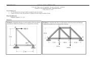
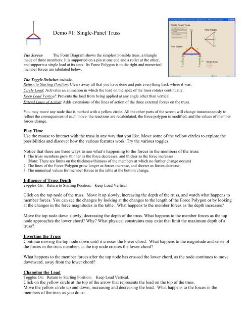
<strong>Demo</strong> <strong>#1</strong>: <strong>Single</strong>-<strong>Panel</strong> <strong>Truss</strong>The Screen The Form Diagram shows the simplest possible truss, a trianglemade of three members. It is supported on a pin <strong>at</strong> one end and a roller <strong>at</strong> the other,and supports a single load <strong>at</strong> its apex. Its Force Polygon is to the right and numericalmember forces are tabul<strong>at</strong>ed below.The Toggle Switches include:Return to Starting Position: Clears away all th<strong>at</strong> you have done and puts everything back where it was.Circle Load: Activ<strong>at</strong>es an anim<strong>at</strong>ion in which the load on the apex of the truss rot<strong>at</strong>es continually.Keep Load Vertical: Prevents the load from being applied <strong>at</strong> any angle other than vertical.Extend Lines of Action: Adds extensions of the lines of action of the three external forces on the truss.You may move any node th<strong>at</strong> is marked with a yellow circle. All the other parts of the screen will change instantaneously toreflect the consequences of each move–the reactions are recalcul<strong>at</strong>ed, the force polygon is modified, and the values of memberforces change.Play TimeUse the mouse to interact with the truss in any way th<strong>at</strong> you like. Move some of the yellow circles to explore thepossibilities and discover how the various fe<strong>at</strong>ures work. Try the various toggles.Notice th<strong>at</strong> there are three ways to see wh<strong>at</strong>’s happening to the forces in the members of the truss:1. The truss members grow thinner as the force decreases, and thicker as the force increases.(Note: There are limits on the thickness/thinness of the members <strong>at</strong> which no further change occurs)2. The lines of the Force Polygon grow longer as forces increase, and shorter as forces decrease.3. The numerical values for member forces in the table <strong>at</strong> the bottom change.Influence of <strong>Truss</strong> DepthToggles On: Return to Starting Position; Keep Load VerticalClick on the top node of the truss. Move it up slowly, increasing the depth of the truss, and w<strong>at</strong>ch wh<strong>at</strong> happens tomember forces. You can see the changes by looking <strong>at</strong> the changes to the length of the Force Polygon or by looking<strong>at</strong> the changes in the force magnitudes in the table. Wh<strong>at</strong> happens to the member forces as the depth increases?Move the top node down slowly, decreasing the depth of the truss. Wh<strong>at</strong> happens to the member forces as the topnode approaches the lower chord? Why? Wh<strong>at</strong> physical constraints may exist th<strong>at</strong> limit the maximum depth of <strong>at</strong>russ?Inverting the <strong>Truss</strong>Continue moving the top node down until it crosses the lower chord. Wh<strong>at</strong> happens to the magnitude and sense ofthe forces in the truss members as the top node crosses the lower chord?Wh<strong>at</strong> happens to the member forces after the top node has crossed the lower chord, as the node continues to movedownward, away from the lower chord?Changing the LoadToggles On: Return to Starting Position; Keep Load Vertical.Click on the yellow circle <strong>at</strong> the top of the arrow th<strong>at</strong> represents the load on the top of the truss.Move the yellow circle up and down, increasing and decreasing the load. Wh<strong>at</strong> happens to the forces in themembers of the truss as you do so.
Changing the Form of the <strong>Truss</strong>Toggles On: Return to Starting Position; Keep Load Vertical.Click on the top node of the truss again and move it from side to side. Wh<strong>at</strong> happens to the reactions as you do this?Wh<strong>at</strong> happens to the member forces?Move the top node slowly leftward until it is directly over the left support. Wh<strong>at</strong> happens to member forces <strong>at</strong> thispoint? Wh<strong>at</strong> happens when the top node moves still farther leftward, outside the left support?Click the Toggle on for “Return to Starting Position,” then move the left support up and down, w<strong>at</strong>ching wh<strong>at</strong>happens to member forces as you do this.Changing the SpanToggles On: Return to Starting Position; Keep Load Vertical.Move the right support rightward, increasing the span of the truss, and note wh<strong>at</strong> happens to member forces. Moveit leftward until the span is very small. Generally speaking, wh<strong>at</strong> is the influence of span on member forces?Changing the Direction of the LoadToggles On: Return to Starting Position. Be sure all other toggles are off.Click on the yellow circle <strong>at</strong> the top of the load arrow and move it left and right. Wh<strong>at</strong> happens to the memberforces as you do this? Wh<strong>at</strong> happens to the reactions? Notice the difference in the directions of the reactions <strong>at</strong> thepin connection and <strong>at</strong> the roller.Align the load so th<strong>at</strong> its line of action runs directly along the axis of one of the top chords of the truss. Wh<strong>at</strong>happens to the forces in the other two truss members when you do this? Wh<strong>at</strong> is the magnitude of the force in themember with which the load is aligned?Concurrence of External ForcesToggles On: Return to Starting Position; Extend Lines of Action.There are three external forces acting on the truss: the load, and the two reactions. Click on the top node of the trussand move it from side to side. The broken green lines extend the lines of action of these forces. Formul<strong>at</strong>e a generalrule about these lines of action.Turn on the Circle Load toggle and w<strong>at</strong>ch wh<strong>at</strong> happens. Does this confirm the rule th<strong>at</strong> you just formul<strong>at</strong>ed? Wh<strong>at</strong>other things can you learn from w<strong>at</strong>ching the action?Wh<strong>at</strong> kinds of loads can be transmitted through a pin connection? Through a roller?
<strong>Demo</strong> #2: Six-<strong>Panel</strong> <strong>Truss</strong>The Screen The Form Diagram shows a six-panel truss with its Force Polygonto the right and a numerical tabul<strong>at</strong>ion of member forces below.The Toggle Switches include:Return to Starting Position: Clears away all th<strong>at</strong> you have done and puts everything back where it was.Gable Form: Converts the truss to a triangular configur<strong>at</strong>ion for a gable roof.Equalize Loads: Maintains all loads <strong>at</strong> the same value.Keep Uniform <strong>Panel</strong> Spacings: Maintains horizontal spacings of vertical members.Keep Verticals Vertical: Maintains vertical members in vertical orient<strong>at</strong>ions.Keep Loads Vertical: Prevents loads from being applied <strong>at</strong> angles other than vertical.Keep Top Chord Level: Maintains a level, horizontal, straight top chord.Keep Bottom Chord Level: Maintains a level, horizontal, straight bottom chord.Top-Bottom Mirror: Keeps the truss symmetrical about its horizontal center line. Only the yellow nodes in the top of the trusscan be moved; the black nodes will move as mirror images of the yellow ones.Left-Right Mirror: Keeps the truss symmetrical about its vertical center line. Only the yellow nodes in the left half of the trusscan be moved; the black nodes will move as mirror images of the yellow ones.Notice the color-coding: Loads are gray, reactions are green. Red is compression, blue is tension, and yellow is zero-force.Members and numbers change color as members change from compression to tension to zero force.Play TimeUse the mouse to play with the truss in any way th<strong>at</strong> you like. Move some of the yellow circles to explore thepossibilities and discover how the various fe<strong>at</strong>ures work. Try the various toggles.Influence of <strong>Truss</strong> DepthToggles On: Keep Verticals Vertical, Keep Top Chord Level, Keep Uniform <strong>Panel</strong> SpacingsIn wh<strong>at</strong> region(s) of the truss are the top and bottom chords most highly loaded? In wh<strong>at</strong> region(s) are the diagonalsmost highly loaded?Click on the leftmost node of the top chord. You’ll find th<strong>at</strong> you can move the entire top chord up and down with it.Move the top chord up slowly, and w<strong>at</strong>ch wh<strong>at</strong> happens to member forces.Move it down slowly, and w<strong>at</strong>ch wh<strong>at</strong> happens to member forces as the top chord approaches the bottom chord.Wh<strong>at</strong> is the general rel<strong>at</strong>ionship between truss depth and member forces? Wh<strong>at</strong> proportion of depth to span seemsmost reasonable to you?
Influence of <strong>Truss</strong> FormToggles On: Return to Starting Position, Left-Right Mirror, Keep Uniform <strong>Panel</strong> Spacing,Keep Loads Vertical, Keep Verticals Vertical, Keep Bottom Chord Level.Move the yellow nodes of the left half of the top chord up and down until you find a form for the top chord suchth<strong>at</strong> the forces in all the interior members of the truss are zero or nearly zero. It’s particularly helpful to w<strong>at</strong>ch theForce Polygon as you do this. Try to make all the lines representing the interior member forces as short as possible.Wh<strong>at</strong> form does the truss take? Does the Force Polygon for this truss resemble the force polygon of any otherstructure th<strong>at</strong> you can think of?Look <strong>at</strong> the numerical values of member forces. Allowing for some vari<strong>at</strong>ion because of the difficulty of achievinga perfect truss form with the mouse, verify th<strong>at</strong> forces in the verticals and diagonals are either zero or very small.Wh<strong>at</strong> generaliz<strong>at</strong>ion can you make about the forces in the six segments of the bottom chord?Keeping the truss form th<strong>at</strong> you have found, Toggle On: Top-Bottom Mirror.Wh<strong>at</strong> happens to the truss? Wh<strong>at</strong> are the unique properties of this truss?Changing of LoadingChanging the Toggles On: Return to Starting Position, Keep Loads Vertical, Keep Uniform <strong>Panel</strong> Spacing, Keep VerticalsVertical, Keep Bottom Chord Level.Change the second load from the right to about three times the value of the other loads. (The Force Polygon mayoverlap the diagram of the form of the truss when you do this. You can move the Force Polygon to a moreconvenient loc<strong>at</strong>ion by clicking and holding on its top yellow circle). By trial and error, find a form for the topchord such th<strong>at</strong> the forces in all the interior members of the truss are zero or nearly zero.Wh<strong>at</strong> form does the truss take? Does the Force Polygon for this truss resemble th<strong>at</strong> of any other structure th<strong>at</strong> youcan think of? Look <strong>at</strong> the numerical values for member forces again. Wh<strong>at</strong> generaliz<strong>at</strong>ions can you make?Form of <strong>Truss</strong>Change the Toggles On: Return to Starting Position, Keep Uniform <strong>Panel</strong> Spacings, Keep Bottom Chord Level,Left-Right Mirror, Keep Loads Vertical.Toggles Off: Keep Verticals Vertical.Experiment with the form of the truss until you find a form of truss with a level bottom chord in which the force isthe same in every segment of the curving top chord. Hint: First find a form th<strong>at</strong> has constant force throughout thelevel bottom chord. Then experiment with the “verticals” in the truss, changing their inclin<strong>at</strong>ions, while you keepan eye on the force polygon to see th<strong>at</strong> the lines th<strong>at</strong> represent the forces in the top chord segments are of about thesame length.Wh<strong>at</strong> is the role of the sloping “verticals” in helping to cre<strong>at</strong>e constant force in the curving chord?Changing Toggles On: Return to Starting Position, Keep <strong>Panel</strong> Spacings, Keep Bottom Chord Level.Double (more or less) the second load from the left. Then change its direction so th<strong>at</strong> it strikes the node of the truss<strong>at</strong> an angle of roughly 60 degrees from the vertical. (Notice wh<strong>at</strong> happens to the green Load Line in the ForcePolygon when you do this). Experiment with this truss until you find a form for it such th<strong>at</strong> it has more or less equalforce throughout the level, bottom chord.
<strong>Demo</strong> #3: Cantilever <strong>Truss</strong>The Screen The Form Diagram shows a truss th<strong>at</strong> cantilevers from a wallwith its Force Polygon to the right.The Toggle Switches include ones from <strong>Demo</strong> #2, plus one new one:Switch Pin and Roller: Click on it and notice wh<strong>at</strong> happens to the reactions and member forces.Influence of <strong>Truss</strong> DepthToggle on: Keep Top Chord LevelWhich members of the truss carry the largest forces? Why?Why are F1 and D8 zero-force members? Wh<strong>at</strong> happens to F1 when you switch the pin and the roller?Click on the upper left-hand node of the truss. Move it up and down, and the entire top chord moves with it.Wh<strong>at</strong> is the general rel<strong>at</strong>ionship between truss depth and member forces?Move the entire top chord down slowly, approaching and finally crossing the lower chord. Wh<strong>at</strong> happens tomember forces as the top chord approaches the lower chord? As it crosses the lower chord?<strong>Truss</strong> FormToggles on: Return to starting position, Keep uniform panel spacing, Keep loads vertical, Keep verticals vertical, Keeptop chord horizontalMake loads AB, BC, & CD each zero. Move the top chord up until you have about doubled the truss depthFind a form for the truss such th<strong>at</strong> all verticals and diagonals have little or no force in them. Wh<strong>at</strong> is the logic of thisform?Toggles on: Keep uniform panel spacing, Keep loads vertical, Keep verticals vertical, Return to starting position,Equalize loadsFind a form for the truss such th<strong>at</strong> all verticals and diagonals have little or no force in them. Wh<strong>at</strong> is the logic of thisform?Toggles on: All the above, plus Top-bottom mirrorFind a form for the truss such th<strong>at</strong> all verticals and diagonals have little or no force in them. Wh<strong>at</strong> is the logic ofthis form?Equilibrium of External ForcesToggles on: Return to starting position, Extend lines of actionMake fairly large changes in individual loads, including sloping some of the loads, and observe the effect of thesechanges on the lines of action of the external forces.Move the supports up and down continuing to observe the lines of action of the external forces.Formul<strong>at</strong>e a general rule about the lines of action of the reactions and the resultant of the loads.
<strong>Demo</strong> #7: Minimum M<strong>at</strong>erial <strong>Truss</strong>The Screen The Form Diagram shows the same six-panel truss th<strong>at</strong> you workedwith in <strong>Demo</strong> #2.There’s a new twist: A rising and falling bar graph keeps track of howmuch your truss design weighs. You can’t change the loads, the span, orthe spacing of the loads, but you can change the form of the truss. Yourtask is to find a truss form th<strong>at</strong> requires the least possible m<strong>at</strong>erial.The Toggle Switches include all the ones you’re familiar with. There’s also a very handy button below the truss, bythe bar graph, th<strong>at</strong> tracks the lowest weight truss found to d<strong>at</strong>a and returns to the best form you’ve found.The program computes the theoretical amount of m<strong>at</strong>erial in the truss by multiplying the amount of force in eachmember by the length of th<strong>at</strong> member, and summing all these quantities. It is assumed in this demonstr<strong>at</strong>ion th<strong>at</strong>compression members will not buckle.Designing a Minimum-M<strong>at</strong>erial <strong>Truss</strong>1. The loading is fixed in a symmetrical p<strong>at</strong>tern. Would there be any advantage for the loading p<strong>at</strong>tern shown tomake the truss itself asymmetrical (not mirrored about a vertical center line)? Wh<strong>at</strong> can you predict about the bestform th<strong>at</strong> will be found for this truss?2. Note th<strong>at</strong> although you cannot move any of the top nodes, the bottom nodes can be moved <strong>at</strong> will. Alsodetermine which of the toggle setting can be used to make your task easier.3. You already know th<strong>at</strong> by making a truss height gre<strong>at</strong>er, the member forces diminish. Can you produce awinning minimum-m<strong>at</strong>erial truss just by making it very, very tall? Why or why not?4. Be sure to try some designs in which the “vertical” members of the truss are no longer vertical.5. When you’re <strong>at</strong> the point of paring the last bits of m<strong>at</strong>erial out of the truss, here’s a str<strong>at</strong>egy th<strong>at</strong> can help: Thecomputer is so fast th<strong>at</strong> it is calcul<strong>at</strong>ing and remembering the volume of m<strong>at</strong>erial in the truss <strong>at</strong> all times, even asyou move nodes around. This means th<strong>at</strong> to fine-tune a good design, you can use the mouse to move each node in ascribbling motion over a very small area. Then hit the “Return to Best Form” button, and the best node loc<strong>at</strong>ion th<strong>at</strong>your curser crossed in its travels will be shown, along with the lowest m<strong>at</strong>erial volume achieved. Repe<strong>at</strong> themaneuver for every node.When You’ve FinishedWh<strong>at</strong> is the logic of the form th<strong>at</strong> you’ve developed? Why does it use less m<strong>at</strong>erial than most other forms? Arethere any real bridges or roof trusses th<strong>at</strong> have this shape? Wh<strong>at</strong> are the advantages/disadvantages of using thisshape truss as a bridge truss? Wh<strong>at</strong> are the advantages/disadvantages of using this shape truss as a roof truss?Most trusses are subjected to a variety of loading p<strong>at</strong>terns when in-service. You have optimized this truss for justone loading p<strong>at</strong>tern. Will it be able to support other p<strong>at</strong>terns as well? How will it do this?