Camless Variable Valve Timing Andrew Butler Dr. M. K. ...
Camless Variable Valve Timing Andrew Butler Dr. M. K. ...
Camless Variable Valve Timing Andrew Butler Dr. M. K. ...

Create successful ePaper yourself
Turn your PDF publications into a flip-book with our unique Google optimized e-Paper software.
<strong>Camless</strong> <strong>Variable</strong> <strong>Valve</strong> <strong>Timing</strong><br />
<strong>Andrew</strong> <strong>Butler</strong><br />
<strong>Dr</strong>. M. K. Ramasubramanian
Various engine systems have been developed in the effort to improve the engine<br />
performance and fuel economy of an automobile. The <strong>Variable</strong> <strong>Valve</strong> <strong>Timing</strong> and Lift Electronic<br />
Control (VTEC) engine is the latest development designed by Honda to enhance the efficiency of<br />
an engine. This system changes cam profiles from the use of synchronized pins controlled and<br />
powered by electro-hydraulic devices. Depending on the speed of the engine, one of the three<br />
different cam profiles are actuated and used to provide the engine with the appropriate amount of<br />
air to achieve a better engine performance and fuel efficiency at that particular range of engine<br />
speeds. As a result, the VTEC provides a degree of fuel economy but the design only offers<br />
optimum engine performance at three different engine speeds. Even though the Honda VTEC has<br />
made substantial efforts toward engine optimization, there is still room to improve on the theory.<br />
The theory behind engine efficiency is to increase the amount of air that is supplied to the engine<br />
as the speed of the engine is increased. From this basic rule of thermodynamics, the idea of<br />
camless variable valve timing (VVT) was conceived.<br />
<strong>Camless</strong> VVT allows an engine to experience maximum engine performance and fuel<br />
efficiency at each and every engine speed while following the same principles of the VTEC.<br />
Instead of using multiple cam profiles with synchronizing pins, camless VVT is electronically<br />
operated by a microcontroller which will control electro-mechanical rotary solenoid actuators.<br />
Due to the required amount of force and speed needed from a solenoid in order for this system to<br />
be effective, linear actuators are ignored since rotary solenoids meet the specifications needed for<br />
this system. Moreover, each of these solenoids will be connected to the intake and exhaust valves<br />
relieving the engine of the load of a cam system. The camshaft alone decreases the mechanical<br />
efficiency of an engine since the friction of the cams and the load of a timing belt increase the
irreversibility’s of an engine. Furthermore, with implementing this design, the flow of air<br />
through the engine’s cylinder can be directly controlled to supply the engine with precise<br />
amounts of air at designated engine speeds while eliminating the old technology of resistive<br />
timing belts and extensive camshafts. Depending on the load and engine speed, the<br />
microcontroller will process the information given and use pulse width modulation (PWM) to<br />
actuate the solenoid valves. These PWMs will generate square waves that are identical to the<br />
timing profile for the most efficient engine at that particular speed and load combination.<br />
Solenoid<br />
Rocker Arm<br />
Solenoid<br />
Actuation<br />
<strong>Valve</strong><br />
Spring<br />
<strong>Valve</strong><br />
Motion<br />
Intake<br />
Port<br />
<strong>Valve</strong><br />
Air<br />
Flow<br />
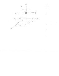
Figure 1: <strong>Camless</strong> VVT Models<br />
As shown above in Figure 1, these PWMs will be sent to the solenoids to actuate the<br />
timing of these devices. Once the solenoid is actuated, the rocker arm pivots and compresses the<br />
valve and valve spring which in turn releases the flow of air into the engine’s cylinder.
Revisiting the idea of engine optimization, theses generated PWMs are predetermined square<br />
waves that will be hard coded and referenced by the microcontroller depending on the load and<br />
speed of the engine for maximum engine efficiency. In order to implement this hypothesis,<br />
engine simulation tools were used to compare the advantages of this design (camless VVT)<br />
versus the Honda VTEC. Through these simulations, the timing events of the exhaust and intake<br />
valves are manipulated to determine the best engine performance that can occur at the desired<br />
engine speed and loading. In addition, the valve lift was also controlled to further analyze the<br />
performance of the engine. Shown below is a screenshot of the program used to simulate the<br />
engine performance of an Acura Integra 1.8L with timing profiles that were tailored for each<br />
engine speed from 1000 rpm to 5500 rpm in 500 rpm increments.<br />
Computer Simulation<br />
Figure 2: Screenshot of Engine Analyzer Pro v3.5
Based on the simulation results, a timing diagram was generated to represent the<br />
maximum engine performance for each designated range of engine speeds. From implementing<br />
this technique, the research found that the valve lift and timing events of the valve train each<br />
independently affect the efficiency of this engine. As a result, these factors were experimentally<br />
balanced to gain the largest amount of engine performance while limiting fuel consumption.<br />
Figure 2 displays the timing profiles of exhaust and intake valves at 1000 rpm, 2500 rpm and<br />
5500 rpm. Neglecting the other 500 rpm increments between 1000 and 5500 rpm, these plots<br />
were organized in this manner in order to illustrate how the timing profiles change as the engine<br />
speed increases.<br />
@ 5500rpm<br />
@ 2500rpm<br />
Exhaust<br />
Intake<br />
@ 1000rpm<br />
Figure 3: <strong>Timing</strong> Diagram using Computer Simulation
After implementing these timing profiles into the engine performance simulator, the<br />
Acura Integra 1.8L engine is compared with the implementation of the “small cam” VTEC<br />
versus the camless VVT system while keeping all other factors constant. From the observed data,<br />
the brake torque of the crankshaft was plotted against the volumetric flow rate of consumed fuel<br />
within the each system. As shown below in Figure 4, overall, the camless VVT system produces<br />
more crankshaft torque while consuming the same amount of fuel for each engine speed.<br />
Figure 4: Engine Performance between the VTEC and <strong>Camless</strong> VVT Systems<br />
From the implementation of computer based simulation for camless variable valve<br />
timing, the results show that this design would improve the fuel economy of an engine by<br />
2.3% overall compared with the Honda VTEC, ranging from a high 6.5% at engine idle to a low
0.3% at mid range speeds. Even though the fuel efficiency would only increase by a small<br />
amount overall if this design was constructed, due to the inability to simulate the gain of not<br />
having the loading effects of a camshaft on the engine, the fuel economy of this design is<br />
underrepresented. However, the research was able to determine that varying the lifts of the intake<br />
and exhaust valves contributes to having the greatest effect on an engine’s performance. More<br />
experiments with this theory will be conducted and a basic model of this design will be<br />
constructed in the near future. Starting with a simple approach, a small lawnmower engine will<br />
be purchased in order to implement this design on a small scale. Removing the camshaft of this<br />
engine and applying the camless VVT system, the actual efficiency of an engine can then be<br />
analyzed with this design and compared with the engine’s original performance.