

Ground fault monitor RCM470LY - Bender
Ground fault monitor RCM470LY - Bender
Ground fault monitor RCM470LY - Bender

You also want an ePaper? Increase the reach of your titles
YUMPU automatically turns print PDFs into web optimized ePapers that Google loves.
BENDER Inc. • 700 Fox Chase, Coatesville PA 19320 • Ph: 800-356-4266 / 610-383-9200 • Fax: 610-383-7100<br />
<strong>Ground</strong> <strong>fault</strong> <strong>monitor</strong> <strong>RCM470LY</strong><br />
<strong>Ground</strong> Fault Monitor / Relay<br />
for <strong>Ground</strong>ed AC Systems<br />
4.1<br />
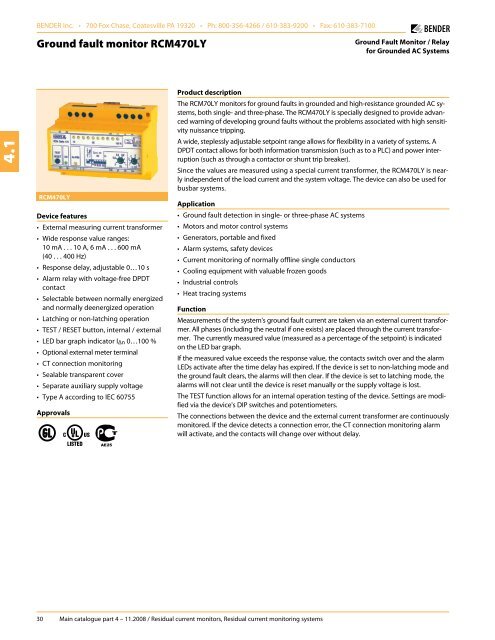
<strong>RCM470LY</strong><br />
Device features<br />
• External measuring current transformer<br />
• Wide response value ranges:<br />
10 mA . . . 10 A, 6 mA . . . 600 mA<br />
(40 . . . 400 Hz)<br />
• Response delay, adjustable 0…10 s<br />
• Alarm relay with voltage-free DPDT<br />
contact<br />
• Selectable between normally energized<br />
and normally deenergized operation<br />
• Latching or non-latching operation<br />
• TEST / RESET button, internal / external<br />
• LED bar graph indicator I Δn 0…100 %<br />
• Optional external meter terminal<br />
• CT connection <strong>monitor</strong>ing<br />
• Sealable transparent cover<br />
• Separate auxiliary supply voltage<br />
• Type A according to IEC 60755<br />
Approvals<br />
Product description<br />
The RCM70LY <strong>monitor</strong>s for ground <strong>fault</strong>s in grounded and high-resistance grounded AC systems,<br />
both single- and three-phase. The <strong>RCM470LY</strong> is specially designed to provide advanced<br />
warning of developing ground <strong>fault</strong>s without the problems associated with high sensitivity<br />
nuissance tripping.<br />
A wide, steplessly adjustable setpoint range allows for flexibility in a variety of systems. A<br />
DPDT contact allows for both information transmission (such as to a PLC) and power interruption<br />
(such as through a contactor or shunt trip breaker).<br />
Since the values are measured using a special current transformer, the <strong>RCM470LY</strong> is nearly<br />
independent of the load current and the system voltage. The device can also be used for<br />
busbar systems.<br />
Application<br />
• <strong>Ground</strong> <strong>fault</strong> detection in single- or three-phase AC systems<br />
• Motors and motor control systems<br />
• Generators, portable and fixed<br />
• Alarm systems, safety devices<br />
• Current <strong>monitor</strong>ing of normally offline single conductors<br />
• Cooling equipment with valuable frozen goods<br />
• Industrial controls<br />
• Heat tracing systems<br />
Function<br />
Measurements of the system's ground <strong>fault</strong> current are taken via an external current transformer.<br />
All phases (including the neutral if one exists) are placed through the current transformer.<br />
The currently measured value (measured as a percentage of the setpoint) is indicated<br />
on the LED bar graph.<br />
If the measured value exceeds the response value, the contacts switch over and the alarm<br />
LEDs activate after the time delay has expired. If the device is set to non-latching mode and<br />
the ground <strong>fault</strong> clears, the alarms will then clear. If the device is set to latching mode, the<br />
alarms will not clear until the device is reset manually or the supply voltage is lost.<br />
The TEST function allows for an internal operation testing of the device. Settings are modified<br />
via the device's DIP switches and potentiometers.<br />
The connections between the device and the external current transformer are continuously<br />
<strong>monitor</strong>ed. If the device detects a connection error, the CT connection <strong>monitor</strong>ing alarm<br />
will activate, and the contacts will change over without delay.<br />
30 Main catalogue part 4 – 11.2008 / Residual current <strong>monitor</strong>s, Residual current <strong>monitor</strong>ing systems
<strong>Ground</strong> <strong>fault</strong> <strong>monitor</strong> <strong>RCM470LY</strong><br />
Wiring diagram – system connection, external connections<br />
Device setup<br />
2<br />
4.1<br />
1<br />
1 2 3 4<br />
9<br />
5 6<br />
7 8<br />
10<br />
A<br />
B<br />
C<br />
D<br />
E<br />
F<br />
}<br />
3<br />
1 - External supply voltage used to power device,<br />
a 6 A fuse recommended for line protection.<br />
4<br />
2 - Connection to external current transformer. All phases, inclu<br />
ding the neutral if one exists, are placed through the CT.<br />
3 - Optional external measuring instrument<br />
4 - External TEST and RESET button terminal<br />
5 - DPDT alarm contact<br />
Note: Do not route the ground conductor through the measuring<br />
current transformer when also routing the power conductors!<br />
5<br />
1 - Combined TEST and RESET button: short depress (< 1s) =<br />
RESET; long depress (> 2s) = TEST<br />
2 - Power On LED<br />
3 - Alarm LED: Illuminates when the response value has been exceeded.<br />
Flashes when the CT connection alarm is active.<br />
4 - LED bar graph indicator: shows the measuring value in percent<br />
of the preset response value.<br />
5 - Potentiometer for setting the response delay (0…1 s).<br />
6 - Potentiometer for setting the response value (x 1…10 mA)<br />
DIP switch settings (white = switch position)<br />
7 - Alarm relay operation settings<br />
A - Normally deenergized<br />
B - Normally energized<br />
8 - Fault memory / latching behavior settings<br />
A - Fault memory ON (latching mode)<br />
B - Fault memory OFF (non-latching mode)<br />
9 - Sample response value settings<br />
<strong>RCM470LY</strong><br />
<strong>RCM470LY</strong>-71..<br />
A - 10 mA<br />
A - 6 mA<br />
B - 30 mA<br />
B - 10 mA<br />
C - 100 mA<br />
x 1…10<br />
C - 20 mA<br />
D - 300 mA<br />
D - 30 mA<br />
x 1…10<br />
E - 500 mA<br />
E - 40 mA<br />
F - 1000 mA F - 60 mA<br />
10 - Time delay settings<br />
A - x 1<br />
0…1 s<br />
B - x 10 }<br />
} }<br />
Main catalogue part 4 – 11.2008 / Residual current <strong>monitor</strong>s, Residual current <strong>monitor</strong>ing systems 31
<strong>Ground</strong> <strong>fault</strong> <strong>monitor</strong> <strong>RCM470LY</strong><br />
Technical data: <strong>Ground</strong> <strong>fault</strong> <strong>monitor</strong> <strong>RCM470LY</strong><br />
4.1<br />
Insulation coordination acc. to IEC 60664-1<br />
Rated insulation voltage<br />
AC 250 V<br />
Rated impulse voltage / pollution degree 4 kV / 3<br />
Voltage ranges<br />
Supply voltage U S<br />
Operating range of U S<br />
Frequency range of U S<br />
Power consumption<br />
see ordering details<br />
0.85…1.1 x U S<br />
DC / 50…400 Hz<br />
≤ 3 VA<br />
Measuring circuit<br />
External measuring current transformers W…, WR…, WS… series<br />
Load<br />
180 Ω<br />
Load <strong>RCM470LY</strong>-72<br />
18 Ω<br />
Operating characteristic acc. to IEC 60755<br />
Type A<br />
Rated residual operating current I Δn <br />
10 mA…10 A / 100 A<br />
Response delay t v, adjustable<br />
0…10 s<br />
Accuracy of response delay + / - 20 %<br />
Rated frequency <br />
40…400 Hz<br />
Relative percentage error 40…400 Hz: 0…- 25 %<br />
400…1000 Hz: 10…- 25 %<br />
Hysteresis<br />
approx. 25 % of the response value<br />
Response time t an at I Δn = 1 x I Δn (t v = 0 s) <br />
≤ 250 ms<br />
Response time t an at IΔn = 5 x IΔn (tv = 0 s)<br />
≤ 20 ms<br />
Number of measuring channels 1<br />
Displays<br />
LED bar graph indicator 0…100 %<br />
LEDs<br />
Power On, Alarm<br />
Inputs/outputs<br />
TEST and RESET button<br />
internal / external<br />
Cable length external TEST and RESET button<br />
≤ 10 m<br />
Current source for external measuring instrument DC 0…400 µA<br />
Load<br />
12.5 kΩ<br />
Cable lengths for measuring current transformers<br />
Single wire ≥ AWG 20 (0.75 mm) 0 . . . 3.2 ft (0…1 m)<br />
Single wire, twisted ≥ AWG 20 (0.75 mm) 0 . . . 32.8 ft (0…10 m)<br />
Shielded cable ≥ AWG 22 (0.5 mm) 0 . . . 131 ft (0…40 m)<br />
Recommended cable (shielded, shield on one side connected<br />
to terminal l of the RCM470, not connected to ground) J-Y(ST)Y min. 2 x 0.8<br />
Switching elements<br />
Number of switching elements 1 DPDT contact<br />
Operating principle, adjustable<br />
normally energized or deenergized<br />
Electrical endurance, number of cycles 12000<br />
Rated contact voltage<br />
AC 250 V / DC 300 V<br />
Limited making capacity<br />
AC / DC 5 A<br />
Breaking capacity 2 A, AC 230 V, PF = 0,4<br />
<br />
0.2 A, DC 220 V, L / R = 0.04 s<br />
Fault memory behavior<br />
ON / OFF (Latching / Non-latching)<br />
General data<br />
EMC immunity acc. to EN 61543<br />
EMC emission acc. to EN 61000-6-4<br />
Shock resistance IEC 60068-2-27 (during operation)<br />
15 g / 11 ms<br />
Bumping IEC 60068-2-29 (during transport)<br />
40 g / 6 ms<br />
Vibration resistance IEC 60068-2-6 (during operation) 1 g / 10…150 Hz<br />
Vibration resistance IEC 60068-2-6 (during transport)<br />
2 g / 10…150 Hz<br />
Ambient temperature, during operation - 10 °C…+ 55 °C<br />
Ambient temperature, when stored - 40 °C…+ 70 °C<br />
Climatic category IEC 60721-3-3<br />
3K5<br />
Operating mode <br />
continuous operation<br />
Mounting <br />
any position<br />
Connection<br />
screw terminals<br />
Connection properties<br />
rigid / flexible AWG 24…12 / 24…14<br />
flexible with ferrules without / with plastic collar AWG 24…14<br />
Conductor sizes (AWG) 24…12<br />
Protection class, internal components (IEC 60529) IP30, NEMA 1<br />
Protection class, terminals (IEC 60529) IP20, NEMA 1<br />
Type of enclosure<br />
X470<br />
Enclosure material<br />
polycarbonate<br />
Screw mounting<br />
2 x M4<br />
DIN rail mounting acc. to IEC 60715<br />
Flammability class<br />
UL94V-0<br />
Standards IEC 62020<br />
Instruction leaflet<br />
BP401003<br />
Weight<br />
≤ 350 g<br />
Ordering information: <strong>Ground</strong> <strong>fault</strong> <strong>monitor</strong> <strong>RCM470LY</strong><br />
Type<br />
Response<br />
range I Δn<br />
Rated<br />
frequency<br />
Response<br />
delay<br />
Measuring<br />
current<br />
transformers<br />
Display<br />
Fault<br />
memory<br />
behaviour<br />
Supply<br />
voltage U S<br />
<strong>RCM470LY</strong> 10 mA…10 A 40…400 Hz 0…10 s W…, WR…, WS… internal / external selectable AC 230 V B 94012017<br />
<strong>RCM470LY</strong>-13 10 mA…10 A 40…400 Hz 0…10 s W…, WR…, WS… internal / external selectable AC 90…132 V* B 94012019<br />
<strong>RCM470LY</strong>-13A 10 mA…10 A 50 / 60 Hz 0…10 s W…, WR…, WS… internal / external selectable AC 90…132 V* B 94012019A<br />
<strong>RCM470LY</strong>-11 10 mA…10 A 40…400 Hz 0…10 s W…, WR…, WS… internal / external selectable AC 24 V B 94012025<br />
<strong>RCM470LY</strong>-21 10 mA…10 A 40…400 Hz 0…10 s W…, WR…, WS… internal / external selectable DC 9.6…84V* B 94012021<br />
<strong>RCM470LY</strong>-23 10 mA…10 A 40…400 Hz 0…10 s W…, WR…, WS… internal / external selectable DC 77…286V* B 94012024<br />
<strong>RCM470LY</strong>-7113 6 mA…600 mA 50 / 60 Hz 0…10 s W…, WR…, WS… internal / external selectable AC 90…132 V* B 94012051<br />
<strong>RCM470LY</strong>-7213 100 mA…100 A 40…400 Hz 0…10 s W…, WR…, WS… internal / external selectable AC 90…132 V* B 94012074<br />
Art. No.<br />
Other supply voltages on request<br />
* Absolute values of the operating range<br />
32 Main catalogue part 4 – 11.2008 / Residual current <strong>monitor</strong>s, Residual current <strong>monitor</strong>ing systems
<strong>Ground</strong> <strong>fault</strong> <strong>monitor</strong> <strong>RCM470LY</strong><br />
Accessories<br />
External measuring current transformers<br />
Type Inside diameter (mm) Art. No.<br />
W20 ø 20 B 9808 0003<br />
W35 ø 35 B 9808 0010<br />
W60 ø 60 B 9808 0018<br />
W120 ø 120 B 9808 0028<br />
W210 ø 210 B 9808 0034<br />
WR70x175 70 x 175 B 9808 0609<br />
WR115x305 115 x 305 B 9808 0610<br />
WS20x30 20 x 30 B 9808 0601<br />
WS50x80 50 x 80 B 9808 0603<br />
WS80x120 80 x 120 B 9808 0606<br />
Other measuring current transformer types on request.<br />
4.1<br />
External panel mounted meter<br />
Type Display range Size (mm) Art. No.<br />
9604-4241 0…100 % 96 x 96 B 986 807<br />
Measuring signal converter<br />
Type Input Output Art. No.<br />
RK170 0…400 µA 0…10 V 0 / 4…20 mA B 9804 1500<br />
Dimension diagram X470<br />
Dimensions in mm<br />
Main catalogue part 4 – 11.2008 / Residual current <strong>monitor</strong>s, Residual current <strong>monitor</strong>ing systems 33


