W21-760-3448 Ford Transit (Dual Rear Wheel with ... - Outdoor Bits
W21-760-3448 Ford Transit (Dual Rear Wheel with ... - Outdoor Bits
W21-760-3448 Ford Transit (Dual Rear Wheel with ... - Outdoor Bits
- No tags were found...

Create successful ePaper yourself
Turn your PDF publications into a flip-book with our unique Google optimized e-Paper software.
1<br />
Unit 626 Kilshane Avenue, North West Business Park, Ballycoolin, Dublin 15, Ireland<br />
Telephone: +353 1 8612 632, Fax: +353 1 8612 647, email: sales@driveriteltd.com<br />
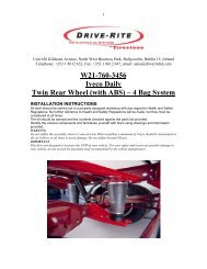
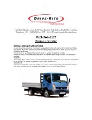
<strong>W21</strong>-<strong>760</strong>-<strong>3448</strong><br />
<strong>Ford</strong> <strong>Transit</strong> (<strong>Dual</strong> <strong>Rear</strong> <strong>Wheel</strong> <strong>with</strong> ABS)<br />
INSTALLATION INSTRUCTIONS<br />
All work should be carried out in a properly equipped workshop <strong>with</strong> due regard to Health and Safety<br />
Regulations. No further reference to Health and Safety Regulations will be made, but they must be<br />
considered at all times.<br />
The kit should be opened and the contents checked against the parts list provided.<br />
Identify the various components and familiarise yourself <strong>with</strong> them using drawings and information<br />
provided.<br />
WARNING<br />
Do not inflate this assembly when it is unrestricted. When installed, a minimum of 10 psi should be maintained in<br />
the air bellows at all times to avoid damage. Do not inflate beyond 100 psi.<br />
IMPORTANT<br />
This kit is not designed to increase the GVW of your vehicle. For your safety and to prevent possible damage to<br />
your vehicle, do not exceed the maximum load recommended by the vehicle manufacturer.
Parts List<br />
Description<br />
QTY<br />
Lower Bracket 2<br />
Upper Left Bracket 1<br />
Upper Right Bracket 1<br />
Axle Strap 2<br />
Locating Plate 1<br />
M10X60 Bolts 4<br />
M10 Locknuts 4<br />
M8X20 Bolt 5<br />
M8x25x2 Flat Washers 4<br />
¼” Inflation Valve 2<br />
M10 X 1.5 x 40 C/sink Bolt 2<br />
M8 Locknut 1<br />
M8 Washer 2<br />
Description<br />
QTY<br />
M10 X 1.25 x 40 C/sink Bolt 2<br />
Cable ties 10<br />
Thermal Sleeves 2<br />
Air Springs 2<br />
18 ft. ¼” tubing 1<br />
3/8 – 15 Flanged locknut 4<br />
3/8 – 16X3/4” Flanged lock bolt 4<br />
¼” Elbow 2<br />
5/16 Flat Washer 4<br />
¼” Tee piece 1<br />
M10 Washers 8<br />
Heat Shield 1<br />
Note About Countersunk Bolts:<br />
There are four M10 countersunk bolts supplied <strong>with</strong> this kit.<br />
2 x M10 x 40 (Standard Thread)<br />
2 x M10 x 1.25 x 40 (Fine Thread)<br />
These bolts are used to mount the upper brackets to the chassis. When the bump stop is<br />
removed the threaded hole must be examined to determine if it is a standard or fine thread.<br />
2
Special Instructions for Air Connections<br />
1. To cut the tubing correctly an appropriate cutter must be used (not a scissors)<br />
2. When inserting the tubing into the connection it must be pushed in approximately<br />
14mm until a click is heard.<br />
3. To remove the tube, push the flange on the connection and at the same time pull the<br />
tube. (No tool is necessary.)<br />
4. ATTENTION, when a tube is removed it is important to trim 14mm from the end<br />
before reconnection.<br />
5. IT is advisable that LOCKTITE be used on the threaded fittings.<br />
Important<br />
• The Installation manual should be read entirely before beginning assembly.<br />
• This kit does not increase the G.V.W. (gross vehicle weight) of your vehicle, for your<br />
safety and to avoid any damage to your vehicle do not exceed the maximum loading<br />
recommended by the manufacturer.<br />
• Do not inflate air bags before assembly.<br />
• Once the kit is installed, do not exceed the max and min pressure limits, incorrect use<br />
or over inflation can cause deterioration of your suspension.<br />
PREPARATION:<br />
In order for the kit to be installed on the vehicle, it is necessary firstly to provide free space<br />
<strong>with</strong>in the range of the rear axle. Usually, there are no additional components which could<br />
interfere <strong>with</strong> installing the kits in this space. However, if components are interfering <strong>with</strong><br />
mounting the kit, then it must be clarified whether it is still possible to mount this kit or whether<br />
these additional parts can be moved accordingly. You must always take care not to interfere<br />
<strong>with</strong> the vehicle parts, e.g. brake hoses, cables etc. These could be jammed or damaged<br />
while assembling the kit. In order to ensure this does not occur, they must be partially shifted.<br />
3
Installation<br />
Raise the chassis from the axle to<br />
create enough room to remove the<br />
bump stops. NOTE: Do not strain any<br />
brake lines or cables.<br />
Remove the original bump stops.<br />
Then remove the metal support by<br />
unscrewing it. The hole will be used to<br />
fix the upper bracket into place.<br />
Take note of the thread on the bump<br />
stop as it may be a standard or fine<br />
thread.<br />
There are C/Sink Bolts provided in the<br />
kit to suit both sizes. The correct sized<br />
bolt must be used.<br />
The top of the air spring has two studs<br />
and an air entrance hole. Attach the<br />
upper bracket to the top of the bellows<br />
using the 3/8” hex nuts and spring<br />
washers provided making sure that the<br />
air entrance hole is exposed in the<br />
bracket opening.<br />
On the exhaust side of the vehicle the<br />
heat shield must be placed between<br />
the air spring and upper bracket <strong>with</strong><br />
the flange in position between the<br />
exhaust pipe and the air spring.<br />
Fix the upper brackets in place of the<br />
original bump stops using the correct<br />
M10 countersunk bolts that have been<br />
determined in part one. (Discard the<br />
other two M10 C/sink Bolts)<br />
To position the lower brackets correctly<br />
onto the axle, cut out the metal collar,<br />
which is being used to hold the electric<br />
wire. During this operation protect the<br />
electric wire and the brake line to<br />
insure they do not get damaged.<br />
Fix the collar to the lower bracket using<br />
one of the M10 x 65 bolts that are used<br />
to attach the lower bracket to the axle<br />
strap.<br />
4
Momentarily move the bracket holding<br />
the brake lines in order to better<br />
position the air bag and lower bracket.<br />
Reposition and tighten all.<br />
Take the bracket holding the brake<br />
lines and carefully reposition using the<br />
original M8 bolt <strong>with</strong> the M8X20 bolt,<br />
M10 locknut, M8 Washers and the<br />
locator plate provided in the Kit.<br />
Note: Use extreme caution when<br />
carrying out this procedure so as<br />
not to damage any of the brake<br />
lines.<br />
Route the longer air tube from the air<br />
spring along the underneath of the<br />
vehicle to the other side and connect<br />
<strong>with</strong> a Tee fitting to the tube from the<br />
other air spring.<br />
Insert a length of air tube into the Tee<br />
fitting and run this tube to the location<br />
chosen for the inflation point.<br />
Cut a long length of tubing in order to connect the valve to the nearest air bag. Do the same<br />
for the opposite side. Choose whether you want separate inflation valves for each side or one<br />
valve common to both sides using the Tee fitting. Use the nylon ties provided to tie the tubing<br />
up into a safe position.<br />
Drill an 8 mm (5/16”) hole and mount<br />
the inflation valve as shown in the<br />
diagram, pushing the valve through the<br />
hole from behind and attaching <strong>with</strong> 2<br />
washers and a nut.<br />
Cut the air tube to length, making sure<br />
the end is cut squarely, and push the<br />
end as far as possible into the back of<br />
the inflation valve.<br />
5
OPTION:<br />
To mount a pressure gauge inside the rear of the vehicle. Cut the air tube squarely a short<br />
distance back from the inflation valve, and insert the ends of the tubes into a Tee fitting. Cut a<br />
length of tube long enough to reach from the Tee fitting to the gauge. Feed the air tube up<br />
from below and connect the tube into the gauge and the Tee fitting.<br />
IMPORTANT:<br />
Attach all tubing securely to the underneath of the vehicle using nylon ties.<br />
Do not attach to brake lines.<br />
Protect the tube <strong>with</strong> the sleeving provided where there are any sharp edges or sources of<br />
heat.<br />
If the vehicle is fitted <strong>with</strong> ABS and Load Sensing Valve (LSV), then adjust the LSV to give<br />
maximum braking (1:1).<br />
If the vehicle is fitted <strong>with</strong> ABS and no LSV, then no brake adjustment is required.<br />
For vehicles <strong>with</strong>out ABS, please contact us on +353 1 8612 632<br />
Examination:<br />
After assembly, inflate air bellows and check all mounting bolts are tight. Screw all<br />
connections tight again. It must be ensured that the mounting brackets can not move. If the<br />
plates touch the brake hose at the air bellows, then these must be moved by suitable means.<br />
After having carried out the assembly, having inflated the Airsprings and<br />
having checked that all the bolts as well as the pneumatic connections are<br />
quite tight. You must make sure that the mounting plates cannot move. If<br />
brackets touch the brake cables towards the Airbags, then they must be<br />
moved <strong>with</strong> adapted means.<br />
Precautions:<br />
Never exceed the maximum and minimum recommended pressure limits.<br />
Min pressure 1bar<br />
Max pressure 7bar<br />
Never drive <strong>with</strong> deflated air bags.<br />
6