W21-760-3456 Iveco Daily Twin Rear Wheel (with ABS) â 4 Bag ...
W21-760-3456 Iveco Daily Twin Rear Wheel (with ABS) â 4 Bag ...
W21-760-3456 Iveco Daily Twin Rear Wheel (with ABS) â 4 Bag ...

Create successful ePaper yourself
Turn your PDF publications into a flip-book with our unique Google optimized e-Paper software.
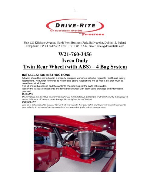
1Unit 626 Kilshane Avenue, North West Business Park, Ballycoolin, Dublin 15, IrelandTelephone: +353 1 8612 632, Fax: +353 1 8612 647, email: sales@driveriteltd.com<strong>W21</strong>-<strong>760</strong>-<strong>3456</strong><strong>Iveco</strong> <strong>Daily</strong><strong>Twin</strong> <strong>Rear</strong> <strong>Wheel</strong> (<strong>with</strong> <strong>ABS</strong>) – 4 <strong>Bag</strong> SystemINSTALLATION INSTRUCTIONSAll work should be carried out in a properly equipped workshop <strong>with</strong> due regard to Health and SafetyRegulations. No further reference to Health and Safety Regulations will be made, but they must beconsidered at all times.The kit should be opened and the contents checked against the parts list provided.Identify the various components and familiarise yourself <strong>with</strong> them using drawings and informationprovided.WARNINGDo not inflate this assembly when it is unrestricted. When installed, a minimum of 10 psi should be maintained inthe air bellows at all times to avoid damage. Do not inflate beyond 100 psi.IMPORTANTThis kit is not designed to increase the GVW of your vehicle. For your safety and to prevent possible damage toyour vehicle, do not exceed the maximum load recommended by the vehicle manufacturer.
- 2 -Parts ListDescription Quantity Description QuantityM10x40 Bolt 16 <strong>Rear</strong> Cross member 1M10x30 Bolt 8 Front Cross member 1M8x30 Bolt 4 Upper Front Right Bracket 1M12x30 Carriage Bolt 12 Upper Front Left Bracket 1M10 Locknut 24 Cable Tie 20M8 Locknut 4 Thermal Sleeve 4M12 Locknut 12 <strong>W21</strong>-<strong>760</strong>-9000 Air spring 4M10 Washer 24 3/8”x1” UNC Bolt 8Lower Front Right Bracket 1 3/8”x3/4” UNC Bolt 4Lower Front Left Bracket 1 1/4 NPT Elbow 4Bottom Bracket 2 Tee Piece 2Lower <strong>Rear</strong> Bracket 2 Inflation Valve 2Upper <strong>Rear</strong> Right Bracket 1 1/4 Tubing 5Upper <strong>Rear</strong> Left Bracket 11. NOTES:This kit uses 4 Tapered Sleeve bellows. This kit is installed in such a way that thereare two bellows mounted in front and two behind the rear axle. Each upper bracket issupported by means of two crossbeams. The lower assembly brackets are attached insuch a way that they bolt around the axle.Note: The assembly of this kit should be carried out by trained technical personnel.This is necessary, as auxiliary tools are required for assembly.2. PREPARATION:In order for the kit to be installed on the vehicle, it is necessary firstly to provide freespace <strong>with</strong>in the range of the rear axle. Usually, there are no additional componentswhich could interfere <strong>with</strong> installing the kits in this space. However, if componentsare interefering <strong>with</strong> mounting the kit, then it must be clarified whether it is stillpossible to mount this kit or whether these additional parts can be moved accordingly.You must always take care not to interfere <strong>with</strong> the vehicle parts, e.g. brake hoses,cables etc. These could be jammed or damaged while assembling the kit. In order toensure this does not occur, they must be partially shifted.3. INSTALLATION:Assembly of the lower bracket:For installation, first, the lowerbracket must be installed. Theassembly of the kit is described nowon the basis of the right hand side ofthe vehicle in the driving direction.Firstly, the brake hose bracket whichis welded onto the axle, must beloosened from the rear axle. Thebracket welded at the rear axle can beremoved using a steel chisel and ahammer (see photo).
- 3 -Take out the lower bracket assembly.This consists of the lower flat bracketplus the top bridging bracket. The topbridging bracket is mounted abovethe axle and the flat bracket isinstalled underneath the axle asshown. During assembly of thebridging bracket, attention must bepaid to aligning the front part of thebracket. With vehicles <strong>with</strong> discbrakes at the rear axle, this recessmust point to the tire side. Ensure thatthe brake hose lines here are nottouching the bracket.Bolt the two upper parts of the lowerbracket together <strong>with</strong> two M8x30bolts (also if necessary the brake hosebracket must be fastened here!) andyou bolt these to the lower channel.Do not damage cables or brake hoses!Assembly of the upper brackets:The picture shows the upper bracketlocating holes. It is now advisable tobolt the air bellows to the lowerbracket. Now you can rotate the airelbow connections at the bellows. Ifthe bellows are fastened to the lowerbracket, this allows you to see wherethe upper brackets must be bolted tothe chassis. The front top brackets aremounted laterally at the original C-section framework in drivingdirection, so that the top points to themiddle of vehicle (see photo).
- 4 -Two holes are usually alreadyavailable on the vehicle chassisframe, if necessary these holes mustbe drilled to the appropriate diameterof the bolt. Additionally, the twoother holes must be drilled in thechassis. Bolt the bracket <strong>with</strong> theM10x40 bolts to the chassis.Subsequently, the bellows can befastened <strong>with</strong> the two upper 3/8”bolts.The rear top bracket is positioned onthe outside of the C-section chassispointing inwards, so that the top ofthe L points to the right frameworkside. The four holes of this bracketline up <strong>with</strong> an already existing holepattern on the vehicle chassis. Then,mount the bellows <strong>with</strong> the two 3/8”screws.Similarly, mount the brackets of the other side of the vehicle as previouly described.Once the top and bottom brackets are mounted, then the cross members are finallybolted in place. These are essential, so that the vehicle frame does not twist.Air connection:With a 4-<strong>Bag</strong>-system the two bellows on each side are connected <strong>with</strong> air lines bymeans of a T-fitting. The 2 T-fittings from each side are subsequently connected <strong>with</strong>another T-fitting. This in turn is connected to a standard inflation valve which ismounted at a convenient location on the vehicle.Examination:After assembly, inflate air bellows and check all mounting bolts are tight. Screw allconnections tight again. It must be ensured that the mounting brackets can not move.If the plates touch the brake hose at the air bellows, then these must be moved bysuitable means.