W21-760-3123 Renault Master Semi Air Kit Double Convoluted ...
W21-760-3123 Renault Master Semi Air Kit Double Convoluted ...
W21-760-3123 Renault Master Semi Air Kit Double Convoluted ...
- No tags were found...

You also want an ePaper? Increase the reach of your titles
YUMPU automatically turns print PDFs into web optimized ePapers that Google loves.
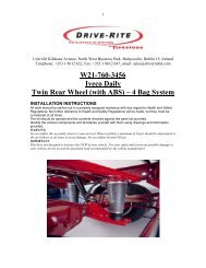
1Unit 626 Kilshane Avenue, North West Business Park, Ballycoolin, Dublin 15, IrelandTelephone: +353 1 8612 632, Fax: +353 1 8612 647, email: sales@driveriteltd.com<strong>W21</strong>-<strong>760</strong>-<strong>3123</strong><strong>Renault</strong> <strong>Master</strong> <strong>Semi</strong> <strong>Air</strong> <strong>Kit</strong><strong>Double</strong> <strong>Convoluted</strong> VersionINSTALLATION INSTRUCTIONSAll work should be carried out in a properly equipped workshop with due regard toHealth and Safety Regulations. No further reference to Health and Safety Regulationswill be made, but they must be considered at all times.The kit should be opened and the contents checked against the parts list provided.Identify the various components and familiarise yourself with them using drawings andinformation provided.WARNINGDo not inflate this assembly when it is unrestricted. When installed, a minimum of 10 psi should bemaintained in the air bellows at all times to avoid damage. Do not inflate beyond 100 psi.IMPORTANTThis kit is not designed to increase the GVW of your vehicle. For your safety and to prevent possibledamage to your vehicle, do not exceed the maximum load recommended by the vehicle manufacturer.
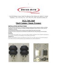
Parts ListDescription Quantity Description Quantity<strong>Air</strong>spring 2 <strong>Air</strong> Fitting 2Upper Bracket 2 Tee Piece 1Lower Bracket 2 Inflation Valve 23/8” Countersunk Screw 4 Cable Tie 10U Bolt 2 Tubing 5m3/8 Washer 4 Thermal Sleeve 23/8 Locknut 4INSTALLATIONUsing 3/8 UNC x ½ ” countersunk boltsassemble the top brackets to theairsprings. Screw in the elbow air fittingsto the top of the airsprings. The use ofthread sealant is recommended here.Using 3/8 UNC x 1” bolts, join the bottombrackets to the airsprings as shown, withthe tongue at the bottom on the sameside as the large air fitting hole at the top.Tighten the bolts. (See torque figuresbelow).Remove the bump stops, but keep thebolts.Decide which side of the vehicle tomount the inflation valve: a suggestedlocation is at the front or rear of the rearwheel arch. It should be easily accessiblebut protected, and on the same side ofthe vehicle as you intend to mount thepressure gauge (if applicable): a suitablelocation for this is inside the rear of thevehicle.Cut 2 lengths of air tube, 1200 mm and300 mm. The shorter tube must be puton the same side as the inflation valve.Thread the tube into the chassis eachside, entering the oval hole to the rear ofthe bump stop bolt hole and exiting thehole between the bolt holes.Insert the tube coming out between thebolt holes into the air fitting on theairspring and feed the whole airspringassembly up into chassis, with the toweron the inner side of the chassis rail.Secure the top bracket to the chassiswith the original bump stop bolts. (Tomake this easier, compress the airspringand hold it with adhesive tape.)2
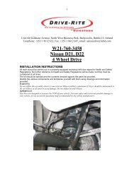
Fit the bottom bracket on the axle tubeand secure with u-bolts, nuts andwashers. The tongue should just touchthe spring.Fully torque the U-bolts and bump stopbolts. (See torque figures below).Route the longer air tube from theairspring along the underneath of thevehicle to the other side and connect witha Tee fitting to the tube from the otherairspring.Insert a length of air tube into the Teefitting and run this tube to the locationchosen for the inflation point.Drill an 8 mm (5/16”) hole and mount theinflation valve as shown in the diagram,pushing the valve through the hole frombehind and attaching with 2 washers anda nut.Cut the air tube to length, making surethe end is cut squarely, and push the endas far as possible into the back of theinflation valve.3
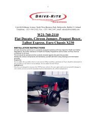
OPTION: To mount a pressure gauge inside the rear of the vehicle. Cut the air tube squarelya short distance back from the inflation valve, and insert the ends of the tubes into a Teefitting. Cut a length of tube long enough to reach from the T fitting to the gauge. Feed the airtube up from below and connect the tube into the gauge and the Tee fitting.IMPORTANT:Attach all tubes securely to the vehicle using nylon ties.Do not attach to brake lines.Protect the tube with the sleeving provided where there are any sharp edges or sources ofheat.If the vehicle is fitted with ABS and LoadSensing Valve (LSV), then adjust theLSV to give maximum braking (1:1).If the vehicle is fitted with ABS and noLSV, then no brake adjustment isrequired.For vehicles without ABS, pleasecontact us on +353 1 8612 632.TORQUE SETTINGSU bolts 3/8 UNC38 Nm10 mm bump stop bolts 50 Nm<strong>Air</strong>spring bolts 3/8 UNC25 NmExamination:After assembly, inflate air bellows and check all mounting bolts are tight. Screw allconnections tight again. It must be ensured that the mounting brackets can not move. If theplates touch the brake hose at the air spring, then these must be moved by suitable means.4