Magnetometer_HMC1052.. - EasySen
Magnetometer_HMC1052.. - EasySen
Magnetometer_HMC1052.. - EasySen
- No tags were found...

Create successful ePaper yourself
Turn your PDF publications into a flip-book with our unique Google optimized e-Paper software.
1, 2 and 3 Axis Magnetic Sensors<br />
HMC1051/HMC1052/HMC1053<br />
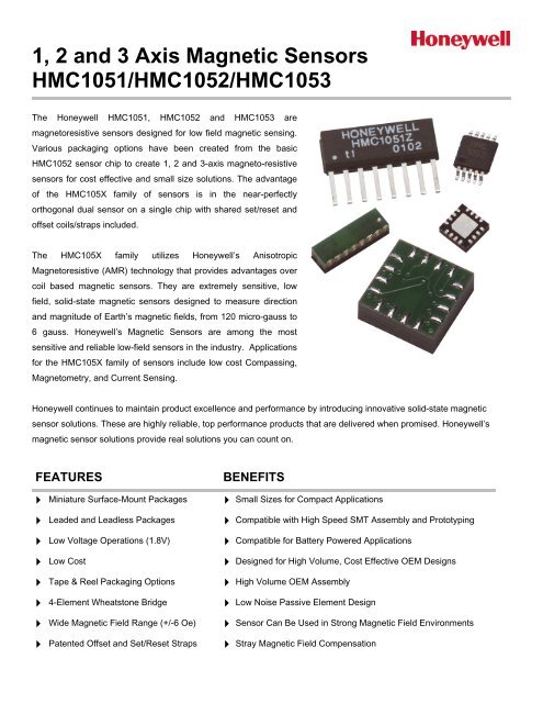
The Honeywell HMC1051, HMC1052 and HMC1053 are<br />
magnetoresistive sensors designed for low field magnetic sensing.<br />
Various packaging options have been created from the basic<br />
HMC1052 sensor chip to create 1, 2 and 3-axis magneto-resistive<br />
sensors for cost effective and small size solutions. The advantage<br />
of the HMC105X family of sensors is in the near-perfectly<br />
orthogonal dual sensor on a single chip with shared set/reset and<br />
offset coils/straps included.<br />
The HMC105X family utilizes Honeywell’s Anisotropic<br />
Magnetoresistive (AMR) technology that provides advantages over<br />
coil based magnetic sensors. They are extremely sensitive, low<br />
field, solid-state magnetic sensors designed to measure direction<br />
and magnitude of Earth’s magnetic fields, from 120 micro-gauss to<br />
6 gauss. Honeywell’s Magnetic Sensors are among the most<br />
sensitive and reliable low-field sensors in the industry. Applications<br />
for the HMC105X family of sensors include low cost Compassing,<br />
Magnetometry, and Current Sensing.<br />
Honeywell continues to maintain product excellence and performance by introducing innovative solid-state magnetic<br />
sensor solutions. These are highly reliable, top performance products that are delivered when promised. Honeywell’s<br />
magnetic sensor solutions provide real solutions you can count on.<br />
FEATURES<br />
BENEFITS<br />
4 Miniature Surface-Mount Packages 4<br />
4 Leaded and Leadless Packages 4<br />
4 Low Voltage Operations (1.8V) 4<br />
4 Low Cost 4<br />
4 Tape & Reel Packaging Options 4<br />
4 4-Element Wheatstone Bridge 4<br />
4 Wide Magnetic Field Range (+/-6 Oe) 4<br />
4 Patented Offset and Set/Reset Straps 4<br />
Small Sizes for Compact Applications<br />
Compatible with High Speed SMT Assembly and Prototyping<br />
Compatible for Battery Powered Applications<br />
Designed for High Volume, Cost Effective OEM Designs<br />
High Volume OEM Assembly<br />
Low Noise Passive Element Design<br />
Sensor Can Be Used in Strong Magnetic Field Environments<br />
Stray Magnetic Field Compensation
HMC1051/HMC1052/HMC1053<br />
SPECIFICATIONS<br />
Characteristics Conditions* Min Typ Max Units<br />
Bridge Elements<br />
Supply Vbridge referenced to GND 1.8 3.0 20 Volts<br />
Resistance Bridge current = 10mA 800 1000 1500 ohms<br />
Operating Temperature Ambient -40 125 °C<br />
Storage Temperature Ambient, unbiased -55 150 °C<br />
Humidity Tested at 85°C 85 %<br />
Field Range Full scale (FS) – total applied field -6 +6 gauss<br />
Linearity Error<br />
Best fit straight line<br />
± 1 gauss<br />
± 3 gauss<br />
± 6 gauss<br />
Hysteresis Error 3 sweeps across ±3 gauss 0.06 %FS<br />
Repeatability Error 3 sweeps across ±3 gauss 0.1 %FS<br />
Bridge Offset<br />
Offset = (OUT+) – (OUT-)<br />
Field = 0 gauss after Set pulse<br />
-1.25 ± 0.5 +1.25 mV/V<br />
Sensitivity Set/Reset Current = 0.5A 0.8 1.0 1.2 mV/V/gauss<br />
Noise Density @ 1kHz, Vbridge=5V 50 nV/sqrt Hz<br />
Resolution 50Hz Bandwidth, Vbridge=5V 120 µgauss<br />
Bandwidth Magnetic signal (lower limit = DC) 5 MHz<br />
Disturbing Field<br />
Sensitivity Tempco<br />
Bridge Offset Tempco<br />
Sensitivity starts to degrade.<br />
Use S/R pulse to restore sensitivity.<br />
T A = -40 to 125°C, Vbridge=5V<br />
T A = -40 to 125°C, Ibridge=5mA<br />
T A = -40 to 125°C, No Set/Reset<br />
T A = -40 to 125°C, With Set/Reset<br />
2 www.honeywell.com<br />
0.1<br />
0.5<br />
1.8<br />
%FS<br />
20 gauss<br />
-3000 -2700<br />
-600<br />
± 500<br />
± 10<br />
-2400 ppm/°C<br />
ppm/°C<br />
Bridge Ohmic Tempco Vbridge=5V, T A = -40 to 125°C 2100 2500 2900 ppm/°C<br />
Cross-Axis Effect Cross field = 1 gauss, Happlied = ±1 gauss ± 3 %FS<br />
Max. Exposed<br />
Field<br />
Sensitivity Ratio of<br />
X,Y Sensors<br />
X,Y sensor<br />
Orthogonality<br />
Set/Reset Strap<br />
No perming effect on zero reading 10000 gauss<br />
T A = -40 to 125°C<br />
(HMC1052 Only)<br />
Sensitive direction in X and Y sensors<br />
(HMC1052)<br />
95 100 105 %<br />
0.01 degree<br />
Resistance Measured from S/R+ to S/R- 3 4.5 6 ohms<br />
Current 0.1% duty cycle, or less, 2µsec current pulse 0.4 0.5 4 Amp<br />
Resistance Tempco T A = -40 to 125°C 3300 3700 4100 ppm/°C<br />
Offset Straps<br />
Resistance Measured from OFFSET+ to OFFSET- 12 15 18 ohms<br />
Offset<br />
Constant<br />
DC Current<br />
Field applied in sensitive direction<br />
10 mA/gauss<br />
Resistance Tempco T A = -40 to 125°C 3500 3900 4300 ppm/°C<br />
* Tested at 25°C except stated otherwise.
HMC1051/HMC1052/HMC1053<br />
PIN CONFIGURATIONS<br />
(Arrow indicates direction of applied field that generates a positive output voltage after a SET pulse.)<br />
HMC1051Z<br />
Vcc<br />
(3)<br />
HMC1051Z Pinout<br />
BRIDGE A<br />
HMC1051<br />
BRIDGE B<br />
HONEYWELL<br />
HMC1051Z<br />
Vo+(A)<br />
(2)<br />
GND Plane<br />
(4)<br />
Vo-(A)<br />
(8)<br />
GND1(B)<br />
(1)<br />
GND2(B)<br />
(5)<br />
1 2 3 4 5 6 7 8<br />
S/R+<br />
(6)<br />
Set/Reset Strap<br />
S/R-<br />
(7)<br />
HMC1051ZL<br />
HMC1051ZL Pinout<br />
8<br />
VB<br />
7<br />
VO+<br />
6<br />
5<br />
4<br />
OFF+<br />
GND VO-<br />
2<br />
1<br />
S/R+<br />
OFF-<br />
3<br />
S/R-<br />
HMC1052<br />
Vcc<br />
(5)<br />
HMC1052 Pinout<br />
10 9 8 7 6<br />
HMC1052<br />
B<br />
BRIDGE A<br />
BRIDGE B<br />
HMC<br />
1052<br />
A<br />
OUT-<br />
(10)<br />
GND2<br />
(9)<br />
GND1<br />
(3)<br />
OUT+<br />
(4)<br />
OUT-<br />
(7)<br />
GND<br />
(1)<br />
OUT+<br />
(2)<br />
1 2 3 4 5<br />
S/R+<br />
(6)<br />
Set/Reset Strap<br />
S/R-<br />
(8)<br />
www.honeywell.com 3
HMC1051/HMC1052/HMC1053<br />
HMC1052L<br />
HMC1052L Pinout<br />
BOTTOM VIEW<br />
OUT-<br />
NC<br />
(B) S/R- NC<br />
9 10 11 12<br />
S/R+<br />
8<br />
B<br />
13<br />
GND1<br />
(A)<br />
GND2<br />
(B)<br />
OFF-<br />
7<br />
6<br />
A<br />
14<br />
15<br />
OUT-<br />
(A)<br />
GND1<br />
(B)<br />
NC<br />
5<br />
16<br />
OUT+<br />
(B)<br />
HMC1053<br />
4<br />
VB<br />
3<br />
OUT+<br />
(A)<br />
2<br />
1<br />
OFF+<br />
GND2<br />
(A)<br />
HMC1053 Pinout<br />
PACKAGE OUTLINES<br />
PACKAGE DRAWING HMC1051Z (8-PIN SIP)<br />
Symbol<br />
A<br />
A1<br />
B<br />
D<br />
E<br />
e<br />
H<br />
h<br />
Millimeters<br />
Min Max<br />
1.371 1.728<br />
0.101 0.249<br />
0.355 0.483<br />
9.829 11.253<br />
3.810 3.988<br />
1.270 ref<br />
6.850 7.300<br />
0.381 0.762<br />
Inches x 10E-3<br />
Min Max<br />
54 68<br />
4 10<br />
14 19<br />
387 443<br />
150 157<br />
50 ref<br />
270 287<br />
15 30<br />
4 www.honeywell.com
HMC1051/HMC1052/HMC1053<br />
PACKAGE DRAWING HMC1051ZL (8-PIN IN-LINE LCC)<br />
PACKAGE DRAWING HMC1052 (10-PIN MSOP)<br />
Symbol<br />
A<br />
A1<br />
b<br />
D<br />
E1<br />
e<br />
E<br />
L1<br />
Millimeters<br />
Min Max<br />
- 1.10<br />
0.05 0.15<br />
0.15 0.30<br />
2.90 3.10<br />
2.90 3.10<br />
0.50 BSC<br />
4.75 5.05<br />
0.95 BSC<br />
Inches x 10E-3<br />
Min Max<br />
- 43<br />
2.0 5.9<br />
5.9 11.8<br />
114 122<br />
114 122<br />
19.7 BSC<br />
187 199<br />
37.4<br />
PACKAGE DRAWING HMC1052L (16-PIN LCC)<br />
Symbol<br />
Millimeters<br />
min max<br />
A 0.80 1.00<br />
A1 0 0.05<br />
A3<br />
0.20 REF<br />
b 0.18 0.30<br />
D<br />
3.00 BSC<br />
D2 1.55 1.80<br />
E<br />
3.00 BSC<br />
E2 1.55 1.80<br />
e<br />
0.50 BSC<br />
L 0.30 0.50<br />
N 16<br />
ND 4<br />
NE 4<br />
r B(min)/2<br />
aaa 0.15<br />
bbb 0.10<br />
ccc 0.10<br />
www.honeywell.com 5
HMC1051/HMC1052/HMC1053<br />
PACKAGE DRAWING HMC1053 (16-PIN LCC)<br />
STENCIL DESIGN AND SOLDER PASTE<br />
A 4 mil stencil and 100% paste coverage is recommended for the electrical contact pads.<br />
REFLOW AND REWORK<br />
The HMC1051ZL and HMC1053 parts should reference application note AN-216. The other part types have no special<br />
profile required and compatible with lead eutectic and lead-free solder paste reflow profiles up to 220°C. Honeywell<br />
recommends the adherence to solder paste manufacturer’s guidelines. The HMC105X parts may be reworked with<br />
soldering irons, but extreme care must be taken not to overheat the copper pads from the part’s fiberglass substrate. Irons<br />
with a tip temperature no greater than 315°C should be used. Excessive rework risks the copper pads pulling away into<br />
the molten solder.<br />
DEVICE OPERATION<br />
The Honeywell HMC105X family of magnetoresistive sensors are Wheatstone bridge devices to measure magnetic fields.<br />
With power supply applied to a bridge, the sensor converts any incident magnetic field in the sensitive axis direction to a<br />
differential voltage output. In addition to the bridge circuit, the sensor has two on-chip magnetically coupled straps; the<br />
offset strap and the set/reset strap. These straps are Honeywell patented features for incident field adjustment and<br />
magnetic domain alignment; and eliminate the need for external coils positioned around the sensors.<br />
The magnetoresistive sensors are made of a nickel-iron (Permalloy) thin-film deposited on a silicon wafer and patterned<br />
as a resistive strip element. In the presence of a magnetic field, a change in the bridge resistive elements causes a<br />
corresponding change in voltage across the bridge outputs.<br />
These resistive elements are aligned together to have a common sensitive axis (indicated by arrows on the pinouts) that<br />
will provide positive voltage change with magnetic fields increasing in the sensitive direction. Because the output only is in<br />
proportion to the one-dimensional axis (the principle of anisotropy) and its magnitude, additional sensor bridges placed at<br />
orthogonal directions permit accurate measurement of arbitrary field direction. The combination of sensor bridges in two<br />
and three orthogonal axis permit applications such as compassing and magnetometry.<br />
The offset strap allows for several modes of operation when a direct current is driven through it. These modes are: 1)<br />
Subtraction (bucking) of an unwanted external magnetic field, 2) null-ing of the bridge offset voltage, 3) Closed loop field<br />
cancellation, and 4) Auto-calibration of bridge gain.<br />
6 www.honeywell.com
HMC1051/HMC1052/HMC1053<br />
The set/reset strap can be pulsed with high currents for the following benefits: 1) Enable the sensor to perform high<br />
sensitivity measurements, 2) Flip the polarity of the bridge output voltage, and 3) Periodically used to improve linearity,<br />
lower cross-axis effects, and temperature effects.<br />
NOISE CHARACTERISTICS<br />
The noise density for the HMR105X series is around 50nV/sqrt Hz at the 1 Hz corner, and quickly drops below 10nV/sqrt<br />
Hz at 5Hz and begins to fit the Johnson Noise value at just below 5nV/sqrt Hz beyond 50Hz. The 10Hz noise voltage<br />
averages around 1.4 micro-volts with a 0.8 micro-volts standard deviation.<br />
CROSS-AXIS EFFECT<br />
Cross-Axis effect for the HMR105X series is typically specified at ±3% of full scale to 1 gauss. See application note<br />
AN215 regarding this effect and methods for nulling.<br />
OFFSET STRAP<br />
The offset strap is a spiral of metalization that couples in the sensor element’s sensitive axis. In two-axis designs, the<br />
strap is common to both bridges and must be multiplexed if each bridge requires a different strap current. In three-axis<br />
designs, the A and B bridges are together with the C bridge sharing a common node for series driving all three bridges’<br />
offset straps. Each offset strap measures nominally 15 ohms, and requires 10mA for each gauss of induced field. The<br />
straps will easily handle currents to buck or boost fields through the ±6 gauss linear measurement range, but designers<br />
should note the extreme thermal heating on the die when doing so.<br />
With most applications, the offset strap is not utilized and can be ignored. Designers can leave one or both strap<br />
connections (Off- and Off+) open circuited, or ground one connection node. Do not tie both strap connections together to<br />
avoid shorted turn magnetic circuits.<br />
SET/RESET STRAP<br />
The set/reset strap is another spiral of metalization that couples to the sensor elements easy axis (perpendicular to the<br />
sensitive axis on the sensor die). Like the offset strap, the set/reset strap runs through a pair of bridge elements to keep<br />
the overall die size compact. Each set/reset strap has a nominal resistance of 3 to 6 ohms with a minimum required peak<br />
current of 400mA for reset or set pulses. With rare exception, the set/reset strap must be used to periodically condition the<br />
magnetic domains of the magneto-resistive elements for best and reliable performance.<br />
A set pulse is defined as a positive pulse current entering the S/R+ strap connection. The successful result would be the<br />
magnetic domains aligned in a forward easy-axis direction so that the sensor bridge’s polarity is a positive slope with<br />
positive fields on the sensitive axis result in positive voltages across the bridge output connections.<br />
A reset pulse is defined as a negative pulse current entering the S/R+ strap connection. The successful result would be<br />
the magnetic domains aligned in a reverse easy-axis direction so that sensor bridge’s polarity is a negative slope with<br />
positive fields on the sensitive axis result in negative voltages across the bridge output connections.<br />
Typically a reset pulse is sent first, followed by a set pulse a<br />
few milliseconds later. By shoving the magnetic domains in<br />
completely opposite directions, any prior magnetic<br />
disturbances are likely to be completely erased by the duet<br />
of pulses. For simpler circuits with less critical requirements<br />
for noise and accuracy, a single polarity pulse circuit may<br />
5 volts<br />
be employed (all sets or all resets). With these uni-polar<br />
pulses, several pulses together become close in<br />
performance to a set/reset pulse circuit. Figure 1 shows a<br />
quick and dirty manual pulse circuit for uni-polar application<br />
of pulses to the set/reset strap. Figure 1<br />
Set Pulse Circuit<br />
Iset<br />
www.honeywell.com 7
HMC1051/HMC1052/HMC1053<br />
APPLICATION NOTES<br />
Low Cost 2-Axis Compass<br />
Very high precision measurements can be made using the HMC105X family of sensors when interfaced with low noise<br />
amplifiers and 12 to 16-bit Analog-to-Digital (A/D) converters. For lower resolution (3° accuracy or more) or low cost<br />
compass applications, 8 or 10-bit A/D converters may be used with general purpose operational amplifiers. Figure 2<br />
shows a typical 2-axis compassing application using readily available off-the-shelf components.<br />
The basic principle of two-axis compassing is to orient the two sensor bridge elements horizontal to the ground<br />
(perpendicular to the gravitational field) and to measure the resulting X and Y analog output voltages. With the amplified<br />
sensor bridge voltages near-simultaneously converted (measured) to their digital equivalents, the arc-tangent Y/X can be<br />
computed to derive the heading information relative to the X-axis sensitive direction. See the application notes on<br />
compassing at Honeywell Magnetic Sensors website (www.magneticsensors.com) for basic principles and detailed<br />
application information.<br />
Vcc<br />
2.5 to 3.6v<br />
U1<br />
1nf<br />
500k<br />
5.00k<br />
LMV358<br />
HMC1052<br />
5.00k<br />
500k<br />
Vref/2<br />
1nf<br />
U2<br />
500k<br />
1<br />
0<br />
U3<br />
MAX1118<br />
enable<br />
data_out<br />
clk_in<br />
5.00k<br />
LMV358<br />
Vref<br />
5.00k<br />
set/reset<br />
.1uf<br />
500k<br />
Vref/2<br />
U4<br />
set/reset<br />
Figure 2<br />
Two-Axis Compass<br />
offset<br />
(2) IRF7509<br />
U5<br />
_set/reset<br />
Set/Reset Circuit Notes<br />
The above set/reset circuit in Figure 1using the IRF7507<br />
dual complementary MOSFETs is shown in detail by Figure<br />
2 in its H-bridge driven configuration. This configuration is<br />
used primarily in battery operated applications were the<br />
500mA nominal set/reset pulsed currents can be best<br />
obtained under low voltage conditions.<br />
The 200-ohm resistor trickle charges the 1uf supply<br />
reservoir capacitor to the Vcc level, and isolates the battery<br />
from the high current action of the capacitors and MOSFET<br />
switches. Under conventional logic states one totem pole<br />
switch holds one node of the 0.1uf capacitor low, while the<br />
other switch charges Vcc into the capacitors opposite node.<br />
At the first logic change, the capacitor exhibits almost a<br />
twice Vcc flip of polarity, giving the series set/reset strap<br />
load plenty of pulse current. A restoring logic state flip uses<br />
the 0.1uf capacitors stored energy to create a second nearly<br />
equal but opposite polarity current pulse through the<br />
set/reset strap.<br />
Rset/reset<br />
4Ω<br />
.1µf<br />
Vsr<br />
S<br />
D<br />
D<br />
S<br />
1µf<br />
+<br />
-<br />
IRF7509(P)<br />
G<br />
G<br />
IRF7509(N)<br />
Vsr<br />
S<br />
D<br />
D<br />
S<br />
IRF7509(P)<br />
G<br />
G<br />
200Ω<br />
IRF7509(N)<br />
Vcc<br />
set/reset<br />
Figure 3<br />
H-Bridge Driver<br />
_set/reset<br />
8 www.honeywell.com
HMC1051/HMC1052/HMC1053<br />
For operation at normal 3.3 or 5-volt logic levels, a single complementary MOSFET pair can be used in a single ended<br />
circuit shown in Figure 4. Other complementary MOSFET pairs can be used with the caution that the chosen devices<br />
should have less than 0.5 ohms ON resistance and be able to handle the needed supply voltages and set/reset currents.<br />
Note that even a 1Hz rate of set/reset function draws an<br />
average current of less than 2 microamperes.<br />
Magnetic Field Detection<br />
For simple magnetic field sensing applications such<br />
Magnetic Anomaly Detectors (MADs) and <strong>Magnetometer</strong>s,<br />
a similar circuit to the compass application can be<br />
implemented using one, two, or three magnetic sensors. In<br />
the example circuit in Figure 5, a HMC1051Z sensor bridge<br />
is used with a low voltage capable dual op-amp to detect<br />
sufficient intensity of a magnetic field in a single direction.<br />
Uses of the circuit include ferrous object detection such as<br />
vehicle detection, a “sniffer” for currents in nearby<br />
conductors, and magnetic proximity switching. By using two<br />
or three sensor circuits with HMC1051, HMC1052, or<br />
HMC1053 parts, a more omni-directional sensing pattern<br />
Rset/reset<br />
Figure 4<br />
Single-Ended Driver<br />
can be implemented. There is nothing special in choosing the resistors for the differential op-amp gain stages other than<br />
having like values (e.g. the two 5kΩ and the 500kΩ resistors) matched at 1% tolerance or better to reject common-mode<br />
interference signals (EMI, RFI). The ratio of the 500kΩ/5kΩ resistors sets the stage gain and can be optimized for a<br />
specific purpose. Typical gain ratios for compass and magnetometer circuits using the HMC105X family, range from 50 to<br />
500. The choice of the 5kΩ value sets impedance loading seen by the sensor bridge network and should be about 4 kiloohms<br />
or higher for best voltage transfer or matching. Note that Figure 5 also shows an alternative set/reset strap driver<br />
circuit using two darlington complentary paired BJTs as electronic switches.<br />
4Ω<br />
.1µf<br />
1µf<br />
+<br />
-<br />
D<br />
D<br />
Vsr<br />
S<br />
S<br />
G<br />
G<br />
200Ω<br />
IRF7509(P)<br />
IRF7509(N)<br />
Vcc<br />
set/reset<br />
Vcc<br />
5.0v<br />
U1<br />
HMC1051<br />
5.00k<br />
5.00k<br />
500k<br />
.1µf<br />
500k<br />
-<br />
TLC072<br />
+<br />
U2<br />
Vcc/2<br />
Vcc<br />
10kΩ pot<br />
Threshold Set<br />
-<br />
TLC072<br />
+<br />
10kΩ<br />
output<br />
LED<br />
* Low ESR Tantalum<br />
1µf*<br />
Vcc<br />
200Ω<br />
RLED<br />
-<br />
+<br />
10kΩ<br />
set/reset<br />
FMMT717<br />
.1uf<br />
FMMT617<br />
0.1µf<br />
set/reset<br />
S<br />
R<br />
offset<br />
10kΩ<br />
0.1µf<br />
Figure 5<br />
Magnetic Field Detector<br />
Alternating or Direct Current Sensing<br />
The HMC105X family sensors can be utilized in a novel way for moderate to high current sensing applications using a<br />
nearby external conductor providing the sensed magnetic field to the bridge. Figure 6 shows a HMC1051Z used as a<br />
current sensor with thermistor element performing a temperature compensation function for greater accuracy over a wide<br />
range of operational temperatures. Selection of the temperature compensation (tempco) resistors used depends on the<br />
thermistor chosen and is dependant on the thermistor’s %/°C shift of resistance. For best op-amp compatibility, the<br />
thermistor resistance should be above about 1000 ohms. The use of a 9-volt alkaline battery supply is not critical to this<br />
application, but permits fairly common operational amplifiers such as the 4558 types to be used. Note that the circuit<br />
must be calibrated based on the final displacement of the sensed conductor to the measuring bridge. Typically, an<br />
optimally oriented measurement conductor can be placed about one centimeter away from the bridge and have<br />
www.honeywell.com 9
HMC1051/HMC1052/HMC1053<br />
reasonable capability of measuring from tens of milliamperes to beyond 20 amperes of alternating or direct currents. See<br />
application note AN-209 for the basic principles of current sensing using AMR bridges.<br />
R tempco<br />
b<br />
R<br />
standoff distance<br />
network<br />
a<br />
Vcc = 9Vdc<br />
U1<br />
.1µf<br />
500k<br />
R th<br />
-<br />
5.00k<br />
RC4458<br />
-<br />
RC4558<br />
+<br />
+<br />
5.00k<br />
U2<br />
500k<br />
Vcc/2 ~ +4.5Vdc<br />
HMC1051<br />
Vcc =9Vdc<br />
* Low ESR Tantalum<br />
200Ω<br />
1µf*<br />
I -<br />
+<br />
ac<br />
output<br />
Figure 6<br />
Current Sensor<br />
I dc<br />
set/reset<br />
.1uf<br />
set/reset<br />
offset<br />
Si1553DL<br />
U3<br />
Conductor to be<br />
Current Measured<br />
Three Axis Compassing with Tilt Compensation<br />
For full three-axis compassing, the circuit depicted in Figure 7 shows both a HMC1051 and a HMC1052 used for sensing<br />
the magnetic field in three axes. Alternatively a single HMC1053 could be used for a single sensor package design. A<br />
two-axis accelerometer with digital (PWM) outputs is also shown to provide pitch and roll (tilt) sensing, to correct the<br />
three-axis magnetic sensors outputs into to the tilt-compensated two-axis heading. The accelerometer can be substituted<br />
with a fluidic 2-axis tilt sensor if desired. For lower voltage operation with Lithium battery supplies (2.5 to 3.6Vdc), the<br />
Set/Reset circuit should be upgraded from a single IRF7507 to the dual IRF7507 implementation (per Figure 2) to permit<br />
a minimum 1-ampere pulse (500mA per set/reset strap resistance) to both the HMC1052 and HMC1051 sensors.<br />
10 www.honeywell.com
HMC1051/HMC1052/HMC1053<br />
Vcc<br />
3.3 to 5.0v<br />
U1<br />
1nf<br />
500k<br />
Vcc<br />
5.00k<br />
5.00k<br />
500k<br />
LMV324<br />
U3<br />
Vcc/2<br />
Vcc/2<br />
AN0<br />
AN1<br />
AN2<br />
AN3<br />
HMC1052<br />
1nf<br />
500k<br />
set/reset<br />
DO0<br />
5.00k<br />
LMV324<br />
U6<br />
set/reset<br />
offset<br />
5.00k<br />
500k<br />
Vcc/2<br />
.1uf<br />
U4<br />
IRF7509<br />
Vcc<br />
U5<br />
µC<br />
with<br />
Multiplexed<br />
A/D Conv.<br />
set/reset<br />
Vcc<br />
U2<br />
.1µf<br />
500k<br />
Two-axis<br />
accelerometer<br />
5.00k<br />
5.00k<br />
500k<br />
-<br />
LMV324<br />
+<br />
Vcc/2<br />
xout<br />
yout<br />
DI0<br />
DI1<br />
HMC1051<br />
Figure 7<br />
Three Axis Compass<br />
Duty Cycling for Lower Energy Consumption<br />
For battery powered and other applications needing limited energy consumption, the sensor bridge and support<br />
electronics can be switched “off” between magnetic field measurements. The HMC105X family of magnetic sensors are<br />
very low capacitance (Bandwidth > 5MHz) sensor bridges and can stabilize quickly, typically before the support<br />
electronics can. Other energy saving ideas would be to minimize the quantity of set/reset pulses which saves energy over<br />
the battery life. Figure 8 shows a simple supply switching circuit that can be microprocessor controlled to duty cycle<br />
(toggle) the electronics in moderate current (
HMC1051/HMC1052/HMC1053<br />
ORDERING INFORMATION<br />
Part Number<br />
HMC1051Z<br />
HMC1051ZL<br />
HMC1052<br />
HMC1052 T/R<br />
HMC1052L<br />
HMC1052L<br />
HMC1053<br />
Package Style<br />
One Axis Magnetic Sensor – SIP8<br />
One Axis Magnetic Sensor – 8-PIN IN-LINE LCC<br />
Two Axis Magnetic Sensors – MSOP10<br />
2,500 units/reel<br />
Two Axis Magnetic Sensors – 16-PIN LCC<br />
3,000 units/reel<br />
Three Axis Magnetic Sensors – 16-PIN LCC<br />
FIND OUT MORE<br />
For more information on Honeywell’s Magnetic Sensors visit us online at www.magneticsensors.com or contact us at<br />
800-323-8295 (763-954-2474 internationally).<br />
The application circuits herein constitute typical usage and interface of Honeywell product. Honeywell does not warranty or assume liability of customerdesigned<br />
circuits derived from this description or depiction.<br />
Honeywell reserves the right to make changes to improve reliability, function or design. Honeywell does not assume any liability arising out of the<br />
application or use of any product or circuit described herein; neither does it convey any license under its patent rights nor the rights of others.<br />
U.S. Patents 4,441,072, 4,533,872, 4,569,742, 4,681,812, 4,847,584 and 6,529,114 apply to the technology described<br />
Honeywell<br />
12001 Highway 55<br />
Plymouth, MN 55441<br />
Form #900308 Rev B<br />
Tel: 800-323-8295<br />
March 2006<br />
www.honeywell.com/magneticsensors<br />
12 ©2006 Honeywell International Inc.<br />
www.honeywell.com