Magnetometer_HMC1052.. - EasySen
Magnetometer_HMC1052.. - EasySen
Magnetometer_HMC1052.. - EasySen
- No tags were found...

You also want an ePaper? Increase the reach of your titles
YUMPU automatically turns print PDFs into web optimized ePapers that Google loves.
HMC1051/HMC1052/HMC1053<br />
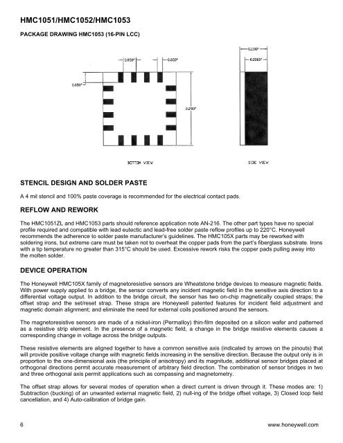
PACKAGE DRAWING HMC1053 (16-PIN LCC)<br />
STENCIL DESIGN AND SOLDER PASTE<br />
A 4 mil stencil and 100% paste coverage is recommended for the electrical contact pads.<br />
REFLOW AND REWORK<br />
The HMC1051ZL and HMC1053 parts should reference application note AN-216. The other part types have no special<br />
profile required and compatible with lead eutectic and lead-free solder paste reflow profiles up to 220°C. Honeywell<br />
recommends the adherence to solder paste manufacturer’s guidelines. The HMC105X parts may be reworked with<br />
soldering irons, but extreme care must be taken not to overheat the copper pads from the part’s fiberglass substrate. Irons<br />
with a tip temperature no greater than 315°C should be used. Excessive rework risks the copper pads pulling away into<br />
the molten solder.<br />
DEVICE OPERATION<br />
The Honeywell HMC105X family of magnetoresistive sensors are Wheatstone bridge devices to measure magnetic fields.<br />
With power supply applied to a bridge, the sensor converts any incident magnetic field in the sensitive axis direction to a<br />
differential voltage output. In addition to the bridge circuit, the sensor has two on-chip magnetically coupled straps; the<br />
offset strap and the set/reset strap. These straps are Honeywell patented features for incident field adjustment and<br />
magnetic domain alignment; and eliminate the need for external coils positioned around the sensors.<br />
The magnetoresistive sensors are made of a nickel-iron (Permalloy) thin-film deposited on a silicon wafer and patterned<br />
as a resistive strip element. In the presence of a magnetic field, a change in the bridge resistive elements causes a<br />
corresponding change in voltage across the bridge outputs.<br />
These resistive elements are aligned together to have a common sensitive axis (indicated by arrows on the pinouts) that<br />
will provide positive voltage change with magnetic fields increasing in the sensitive direction. Because the output only is in<br />
proportion to the one-dimensional axis (the principle of anisotropy) and its magnitude, additional sensor bridges placed at<br />
orthogonal directions permit accurate measurement of arbitrary field direction. The combination of sensor bridges in two<br />
and three orthogonal axis permit applications such as compassing and magnetometry.<br />
The offset strap allows for several modes of operation when a direct current is driven through it. These modes are: 1)<br />
Subtraction (bucking) of an unwanted external magnetic field, 2) null-ing of the bridge offset voltage, 3) Closed loop field<br />
cancellation, and 4) Auto-calibration of bridge gain.<br />
6 www.honeywell.com