Magnetometer_HMC1052.. - EasySen
Magnetometer_HMC1052.. - EasySen
Magnetometer_HMC1052.. - EasySen
- No tags were found...

You also want an ePaper? Increase the reach of your titles
YUMPU automatically turns print PDFs into web optimized ePapers that Google loves.
HMC1051/HMC1052/HMC1053<br />
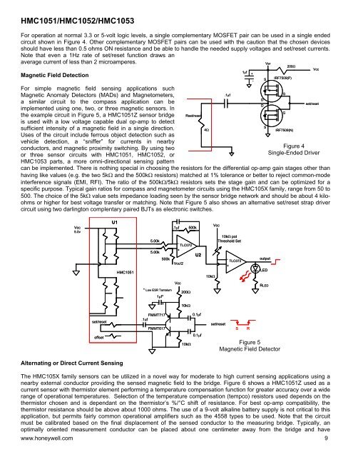
For operation at normal 3.3 or 5-volt logic levels, a single complementary MOSFET pair can be used in a single ended<br />
circuit shown in Figure 4. Other complementary MOSFET pairs can be used with the caution that the chosen devices<br />
should have less than 0.5 ohms ON resistance and be able to handle the needed supply voltages and set/reset currents.<br />
Note that even a 1Hz rate of set/reset function draws an<br />
average current of less than 2 microamperes.<br />
Magnetic Field Detection<br />
For simple magnetic field sensing applications such<br />
Magnetic Anomaly Detectors (MADs) and <strong>Magnetometer</strong>s,<br />
a similar circuit to the compass application can be<br />
implemented using one, two, or three magnetic sensors. In<br />
the example circuit in Figure 5, a HMC1051Z sensor bridge<br />
is used with a low voltage capable dual op-amp to detect<br />
sufficient intensity of a magnetic field in a single direction.<br />
Uses of the circuit include ferrous object detection such as<br />
vehicle detection, a “sniffer” for currents in nearby<br />
conductors, and magnetic proximity switching. By using two<br />
or three sensor circuits with HMC1051, HMC1052, or<br />
HMC1053 parts, a more omni-directional sensing pattern<br />
Rset/reset<br />
Figure 4<br />
Single-Ended Driver<br />
can be implemented. There is nothing special in choosing the resistors for the differential op-amp gain stages other than<br />
having like values (e.g. the two 5kΩ and the 500kΩ resistors) matched at 1% tolerance or better to reject common-mode<br />
interference signals (EMI, RFI). The ratio of the 500kΩ/5kΩ resistors sets the stage gain and can be optimized for a<br />
specific purpose. Typical gain ratios for compass and magnetometer circuits using the HMC105X family, range from 50 to<br />
500. The choice of the 5kΩ value sets impedance loading seen by the sensor bridge network and should be about 4 kiloohms<br />
or higher for best voltage transfer or matching. Note that Figure 5 also shows an alternative set/reset strap driver<br />
circuit using two darlington complentary paired BJTs as electronic switches.<br />
4Ω<br />
.1µf<br />
1µf<br />
+<br />
-<br />
D<br />
D<br />
Vsr<br />
S<br />
S<br />
G<br />
G<br />
200Ω<br />
IRF7509(P)<br />
IRF7509(N)<br />
Vcc<br />
set/reset<br />
Vcc<br />
5.0v<br />
U1<br />
HMC1051<br />
5.00k<br />
5.00k<br />
500k<br />
.1µf<br />
500k<br />
-<br />
TLC072<br />
+<br />
U2<br />
Vcc/2<br />
Vcc<br />
10kΩ pot<br />
Threshold Set<br />
-<br />
TLC072<br />
+<br />
10kΩ<br />
output<br />
LED<br />
* Low ESR Tantalum<br />
1µf*<br />
Vcc<br />
200Ω<br />
RLED<br />
-<br />
+<br />
10kΩ<br />
set/reset<br />
FMMT717<br />
.1uf<br />
FMMT617<br />
0.1µf<br />
set/reset<br />
S<br />
R<br />
offset<br />
10kΩ<br />
0.1µf<br />
Figure 5<br />
Magnetic Field Detector<br />
Alternating or Direct Current Sensing<br />
The HMC105X family sensors can be utilized in a novel way for moderate to high current sensing applications using a<br />
nearby external conductor providing the sensed magnetic field to the bridge. Figure 6 shows a HMC1051Z used as a<br />
current sensor with thermistor element performing a temperature compensation function for greater accuracy over a wide<br />
range of operational temperatures. Selection of the temperature compensation (tempco) resistors used depends on the<br />
thermistor chosen and is dependant on the thermistor’s %/°C shift of resistance. For best op-amp compatibility, the<br />
thermistor resistance should be above about 1000 ohms. The use of a 9-volt alkaline battery supply is not critical to this<br />
application, but permits fairly common operational amplifiers such as the 4558 types to be used. Note that the circuit<br />
must be calibrated based on the final displacement of the sensed conductor to the measuring bridge. Typically, an<br />
optimally oriented measurement conductor can be placed about one centimeter away from the bridge and have<br />
www.honeywell.com 9