Magnetometer_HMC1052.. - EasySen
Magnetometer_HMC1052.. - EasySen
Magnetometer_HMC1052.. - EasySen
- No tags were found...

Create successful ePaper yourself
Turn your PDF publications into a flip-book with our unique Google optimized e-Paper software.
HMC1051/HMC1052/HMC1053<br />
APPLICATION NOTES<br />
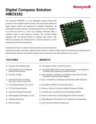
Low Cost 2-Axis Compass<br />
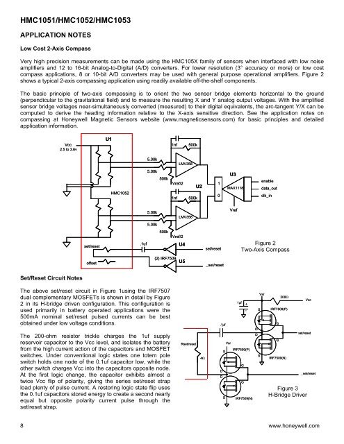
Very high precision measurements can be made using the HMC105X family of sensors when interfaced with low noise<br />
amplifiers and 12 to 16-bit Analog-to-Digital (A/D) converters. For lower resolution (3° accuracy or more) or low cost<br />
compass applications, 8 or 10-bit A/D converters may be used with general purpose operational amplifiers. Figure 2<br />
shows a typical 2-axis compassing application using readily available off-the-shelf components.<br />
The basic principle of two-axis compassing is to orient the two sensor bridge elements horizontal to the ground<br />
(perpendicular to the gravitational field) and to measure the resulting X and Y analog output voltages. With the amplified<br />
sensor bridge voltages near-simultaneously converted (measured) to their digital equivalents, the arc-tangent Y/X can be<br />
computed to derive the heading information relative to the X-axis sensitive direction. See the application notes on<br />
compassing at Honeywell Magnetic Sensors website (www.magneticsensors.com) for basic principles and detailed<br />
application information.<br />
Vcc<br />
2.5 to 3.6v<br />
U1<br />
1nf<br />
500k<br />
5.00k<br />
LMV358<br />
HMC1052<br />
5.00k<br />
500k<br />
Vref/2<br />
1nf<br />
U2<br />
500k<br />
1<br />
0<br />
U3<br />
MAX1118<br />
enable<br />
data_out<br />
clk_in<br />
5.00k<br />
LMV358<br />
Vref<br />
5.00k<br />
set/reset<br />
.1uf<br />
500k<br />
Vref/2<br />
U4<br />
set/reset<br />
Figure 2<br />
Two-Axis Compass<br />
offset<br />
(2) IRF7509<br />
U5<br />
_set/reset<br />
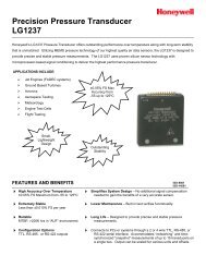
Set/Reset Circuit Notes<br />
The above set/reset circuit in Figure 1using the IRF7507<br />
dual complementary MOSFETs is shown in detail by Figure<br />
2 in its H-bridge driven configuration. This configuration is<br />
used primarily in battery operated applications were the<br />
500mA nominal set/reset pulsed currents can be best<br />
obtained under low voltage conditions.<br />
The 200-ohm resistor trickle charges the 1uf supply<br />
reservoir capacitor to the Vcc level, and isolates the battery<br />
from the high current action of the capacitors and MOSFET<br />
switches. Under conventional logic states one totem pole<br />
switch holds one node of the 0.1uf capacitor low, while the<br />
other switch charges Vcc into the capacitors opposite node.<br />
At the first logic change, the capacitor exhibits almost a<br />
twice Vcc flip of polarity, giving the series set/reset strap<br />
load plenty of pulse current. A restoring logic state flip uses<br />
the 0.1uf capacitors stored energy to create a second nearly<br />
equal but opposite polarity current pulse through the<br />
set/reset strap.<br />
Rset/reset<br />
4Ω<br />
.1µf<br />
Vsr<br />
S<br />
D<br />
D<br />
S<br />
1µf<br />
+<br />
-<br />
IRF7509(P)<br />
G<br />
G<br />
IRF7509(N)<br />
Vsr<br />
S<br />
D<br />
D<br />
S<br />
IRF7509(P)<br />
G<br />
G<br />
200Ω<br />
IRF7509(N)<br />
Vcc<br />
set/reset<br />
Figure 3<br />
H-Bridge Driver<br />
_set/reset<br />
8 www.honeywell.com