Tusk Enduro Lighting Kit Instructions - Rocky Mountain ATV/MC
Tusk Enduro Lighting Kit Instructions - Rocky Mountain ATV/MC
Tusk Enduro Lighting Kit Instructions - Rocky Mountain ATV/MC
- No tags were found...

You also want an ePaper? Increase the reach of your titles
YUMPU automatically turns print PDFs into web optimized ePapers that Google loves.
1<br />
<strong>Tusk</strong> <strong>Enduro</strong> <strong>Lighting</strong> <strong>Kit</strong> <strong>Instructions</strong><br />
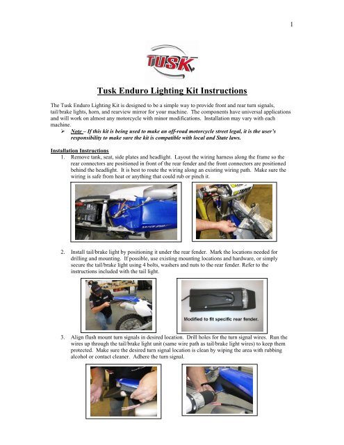
The <strong>Tusk</strong> <strong>Enduro</strong> <strong>Lighting</strong> <strong>Kit</strong> is designed to be a simple way to provide front and rear turn signals,<br />
tail/brake lights, horn, and rearview mirror for your machine. The components have universal applications<br />
and will work on almost any motorcycle with minor modifications. Installation may vary with each<br />
machine.<br />
‣ Note – If this kit is being used to make an off-road motorcycle street legal, it is the user’s<br />
responsibility to make sure the kit is compatible with local and State laws.<br />
Installation <strong>Instructions</strong><br />
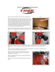
1. Remove tank, seat, side plates and headlight. Layout the wiring harness along the frame so the<br />
rear connectors are positioned in front of the rear fender and the front connectors are positioned<br />
behind the headlight. It is best to route the wiring along an existing wiring path. Make sure the<br />
wiring is safe from heat or anything that could rub or pinch it.<br />
2. Install tail/brake light by positioning it under the rear fender. Mark the locations needed for<br />
drilling and mounting. If possible, use existing mounting locations and hardware, or simply<br />
secure the tail/brake light using 4 bolts, washers and nuts to the rear fender. Refer to the<br />
instructions included with the tail light.<br />
3. Align flush mount turn signals in desired location. Drill holes for the turn signal wires. Run the<br />
wires up through the tail/brake light unit (same wire path as tail/brake light wires) to keep them<br />
protected. Make sure the desired turn signal location is clean by wiping the area with rubbing<br />
alcohol or contact cleaner. Adhere the turn signal.
2<br />
4. With the rear turn signals and tail/brake light in place,<br />
plug signals and tail/brake light into the wiring harness.<br />
(Both black wires from the signals connect to the<br />
double connector black wire from harness. Yellow<br />
wires from signals connect to the orange (left) and blue<br />
(right) wires on the harness).<br />
5. Install brake switch by removing the stock banjo bolt<br />
from the master cylinder and replacing it with the hydraulic brake switch (some machines may not<br />
have room on the master cylinder for the brake switch. In this case it can be installed on the<br />
caliper). It is best to pour brake fluid into the switch before installing. This will eliminate as<br />
much air as possible. After the switch is installed, the rear brake must be bled to remove any<br />
air that entered when the switch was installed. Refer to your owner’s manual for brake<br />
bleeding instructions as the process will vary. Plug the wires from the brake switch into the Pink<br />
wire leads from the harness.<br />
6. Install On/Off switch and control switch to the handlebars<br />
in a suitable location. Route the wires along the<br />
handlebar to the area behind the headlight.<br />
7. Install the horn and flasher relay. These can be installed<br />
in multiple locations on the front of the machine. Choose<br />
a location most suitable for your application. The<br />
mounting hole can be drilled larger if needed. Velcro with an adhesive back (not included) may<br />
be used on the flasher relay if desired.<br />
8. Install front turn signals. If you are using the “mini stalk” turn signals, they can be installed by<br />
drilling mounting holes to the plastic headlight housing. The “handguard’ signals can be installed<br />
to the handlebars with the included mounts, or can be installed directly to aluminum wrap-around<br />
style handguards (<strong>Tusk</strong> part # 1096330001 – sold separately).
3<br />
9. Making sure the wire paths are clean and won’t interfere with anything, go ahead and plug in horn,<br />
signals, relay, on/off switch, and control switch to the wiring harness. (refer to wiring diagram<br />
that came with the harness)<br />
10. Connect the battery. If your bike is equipped with a battery, connect the battery leads included<br />
with the wiring harness (red +, black -). If you don’t have a battery, the <strong>Tusk</strong> battery pack must be<br />
installed. Install the battery pack under the seat or in the airbox to protect it from moisture.<br />
Velcro (included with the battery) can be used to adhere the battery pack (clean surface<br />
thoroughly). Use additional ties if needed for your application.<br />
11. Double check the wiring by referring to harness wiring diagram. Plug the battery into the harness<br />
and test the kit. Turn the On/Off switch to the “On” position. The tail light should be on. Test the<br />
turn signals, horn, and brake to make sure everything is functioning. If there are problems, double<br />
check all wiring and 5 amp fuse.<br />
12. Secure wires. Using zip-ties, secure the wire harness and loose wires. Make certain the wiring<br />
will not interfere will steering or any other functions. Also make sure the wiring is protected from<br />
anything that could cause damage from heat, rubbing, or pinching.<br />
13. Install the mirror. This can be installed upward or downwards depending on preference. Often<br />
times, the mirror works better downwards when it has to be mounted further inwards on the<br />
handlebar. In either position, the mirror can be folded inward when not in use.<br />
14. Install tank, seat, side plates and headlight. Again, double check the wiring to make sure there is<br />
no interference with steering or any other functions.<br />
Additional options<br />
‣ There is a red and black pair of wires extending from the front of the harness. These are used to<br />
plug into the brake switch used on the front brake master cylinder if desired (optional – extra<br />
switch must be purchased separately).<br />
‣ The 3 additional wires (black, White, Blue) from the control switch are used to control the<br />
headlight if desired.<br />
o Black – Headlight main<br />
o White – Low beam<br />
o Dark blue – High beam