

Download - O scale trains
Download - O scale trains
Download - O scale trains
- No tags were found...

You also want an ePaper? Increase the reach of your titles
YUMPU automatically turns print PDFs into web optimized ePapers that Google loves.
AC<br />
IN<br />
AC<br />
IN<br />
RAIL<br />
1<br />
FROG<br />
RAIL<br />
2<br />
RECT.<br />
RECT.<br />
RECT.<br />
RECT.<br />
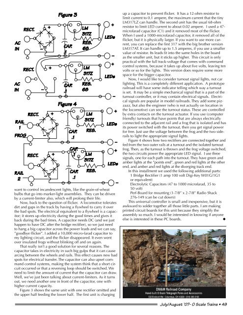
Figure 3<br />
CAP.<br />
.1<br />
CAP.<br />
.1<br />
Figure 4<br />
CAP.<br />
.1<br />
CAP.<br />
.1<br />
CAP.<br />
.1<br />
LM<br />
317Z<br />
RES.<br />
68<br />
LM<br />
317Z<br />
RES.<br />
68<br />
LM<br />
317Z<br />
RES.<br />
LM<br />
317Z<br />
RES.<br />
LEDs<br />
LEDs<br />
LEDs<br />
LEDs<br />
want to control incandescent lights, like the grain-of-wheat<br />
bulbs that go into marker-light assemblies. They can be driven<br />
by a current-limiter also, which will prolong their life.<br />
Now, back to the question of flicker. A locomotive tolerates<br />
dirt and gaps in the track by having a flywheel to carry it over<br />
the bad spots. The electrical equivalent to a flywheel is a capacitor;<br />
it stores up electricity during the good times and gives it<br />
back during the bad times. A capacitor needs DC (and we just<br />
happen to have DC after the bridge rectifier), so we just need<br />
to hang a big capacitor across the power leads and we can say,<br />
”goodbye flicker”. I added a 10,000 micro-farad capacitor to<br />
my lighting circuit, and the flicker disappeared. It even went<br />
over insulated frogs without blinking off and on again.<br />
That really isn’t a good solution for several reasons. The<br />
capacitor takes in electricity in such big gulps that it can cause<br />
arcing between the wheels and rails. This effect causes new bad<br />
spots for electrical transfer. The capacitor can also upset command<br />
control systems, making the system think that a short circuit<br />
occurred or that a reversing loop should be switched. We<br />
need to limit the amount of current that the capacitor can draw.<br />
Well, we’ve just been talking about current-limiters. As it turns<br />
out, we need another one in front of the capacitor, one with<br />
higher current capacity.<br />
Figure 3 shows the same unit with one rectifier omitted and<br />
the upper half feeding the lower half. The first unit is charging<br />
up a capacitor to prevent flicker. It has a 12-ohm resistor to<br />
limit current to 0.1 ampere, the maximum current that the tiny<br />
LM317LZ can handle. The second unit has the usual 68-ohm<br />
resistor to limit LED current to about 0.02 ampere. I used a 47-<br />
microfarad capacitor (C1) and it removed most of the flicker.<br />
When I used a 1000-microfarad capacitor, it removed all of the<br />
flicker, but it is physically larger. If you want to use more current,<br />
you can replace the first 317 with the big brother version<br />
LM317AT. It can handle up to 1.5 amperes, if you use a smaller<br />
value of resistor. Its leads fit into the same holes in the board<br />
as the smaller unit, but it sticks up higher. This circuit is only<br />
practical with the full track-voltage that comes with command<br />
control systems, because it takes up about five volts, leaving ten<br />
volts or so for the lights. This version does require some more<br />
space for the bigger capacitor.<br />
Now, I would like to consider turnout signal lights, not car<br />
lighting. This is a completely different application. A prototype<br />
railroad will have some indicator telling which way a turnout<br />
is set. It may be a simple mechanical signal that is a part of the<br />
turnout controller, or it may contain electrical signals. Electrical<br />
signals are popular in model railroads. They add some pizzazz,<br />
but also the engineer (who is not actually on location in<br />
the locomotive) can see the turnout status. These are controlled<br />
by extra contacts on the turnout actuator. If you use (computer<br />
friendly) turnouts that have points that are always electrically<br />
connected to the adjacent rail and a frog that is isolated and has<br />
its power switched with the turnout, then you get signal power<br />
for free. Just use the voltage between the frog and the two siderails<br />
to light the appropriate signal lights.<br />
Figure 4 shows how two rectifiers are connected together and<br />
fed from the two outer rails at a turnout and the isolated turnout<br />
frog. Then, as the turnout is thrown and the frog voltage switched,<br />
the two circuits power the appropriate LED signal. I use three<br />
signals, one for each path into the turnout. They have green and<br />
amber lights at the ”points end”, green and red lights at the other<br />
end, and amber and red lights at the diverging track end.<br />
In this installment we used the following additional parts:<br />
1 Bridge Rectifier (1 amp 100 volt Digi-Key W01G/1G1<br />
or equivalent)<br />
Electrolytic Capacitors (47 to 1000 microfarad, 35 to<br />
50 volt)<br />
Perf-Board for mounting (1-7/8” x 2-7/8” Radio Shack<br />
276-149 (can be cut down))<br />
This universal controller is small and inexpensive, but it is<br />
awkward to solder together all those little parts. I am making<br />
printed circuit boards for this unit because they simplify the<br />
assembly so much. I would be interested in knowing if anyone<br />
else is interested in these PC boards.<br />
u<br />
July/August ’07- O Scale Trains • 49


