

Download - O scale trains
Download - O scale trains
Download - O scale trains
- No tags were found...

You also want an ePaper? Increase the reach of your titles
YUMPU automatically turns print PDFs into web optimized ePapers that Google loves.
DCC For Traction Layouts<br />
David Gairo<br />
1<br />
I was born and raised in Philadelphia when there were still a<br />
lot of trolleys operating. I rode them all over the city. I have been<br />
building and operating model trolleys since 1965, and I am very<br />
much involved with the trolley museum in Scranton, Pennsylvania,<br />
and one of the organizations that became a part of the volunteer<br />
group there. With a background of operating and riding<br />
the real thing for many years, I want to have my model trolleys<br />
operate as much like them as possible.<br />
I like city trolley operation with complicated trackwork in<br />
the streets. A previous layout, measuring only six by eight feet,<br />
had 21 blocks and 30 track switches incorporated into it. Before<br />
digital command control (DCC), I was limited to carefully running<br />
two trolleys at a time. This was accomplished with a lot of<br />
block-toggle throwing. Now, with DCC, I can have a car pull<br />
up behind another car at a car stop and have multiple cars at<br />
an intersection at the same time. The limitation is the number of<br />
throttles available and people to run them. Even that can be gotten<br />
around with a computer!<br />
A decoder is the controller for every powered unit on a DCC<br />
layout. It recognizes commands addressed to that car (trolley or<br />
locomotive) and controls its motor. For my O Scale trolleys, I use<br />
HO decoders rated for 1.2 to 1.5 amps because most O trolleys<br />
use HO motors in their power trucks. Even the older open-frame<br />
motors (DC-60 size) will operate well on these decoders. I have<br />
used decoders from most DCC manufacturers. I generally select<br />
the basic models, as I do not require a bunch of functions since I<br />
wire the car’s interior lights on all the time and only use the forward<br />
and reverse headlight functions of the decoder. All decoders<br />
include the two headlight functions.<br />
Everyone who writes about selecting decoders tells you to<br />
test the ”stall” current of your motor. I cannot remember ever<br />
stalling a motor. I weight my cars to slip the wheels if the load<br />
is too much. I then select a decoder that handles the ”normal”<br />
motor load. I have not lost a decoder yet. You decide! By the<br />
way, don’t forget that any lights driven by the decoder have to be<br />
added to the total load.<br />
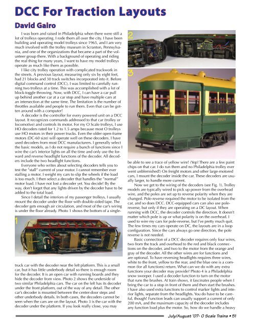
Since I detail the interiors of my passenger trolleys, I usually<br />
mount the decoder under the floor with double-sided tape. The<br />
decoder gets enough air circulation, and most of the car’s wiring<br />
is under the floor already. Photo 1 shows the bottom of a singletruck<br />
car with the decoder near the left platform. This is a small<br />
car, but it has little underbody detail so there is enough room<br />
for the decoder. It is an open car with running boards and they<br />
hide the decoder from view. Photo 2 shows the underside of<br />
two similar Philadelphia cars. The car on the left has its decoder<br />
under the front platform, out of the way of any detail. The other<br />
car’s decoder is mounted between the center-door steps and<br />
other underbody details. In both cases, the decoders cannot be<br />
seen when the cars are on the layout. Photo 3 is the car with the<br />
decoder under the platform. If you look really close, you may<br />
2<br />
3<br />
be able to see a trace of yellow wire! (Yep! There are a few paint<br />
chips on that car. I do run them and no Philadelphia trolley ever<br />
went unblemished!) On freight motors and other large-motored<br />
cars, I mount the decoder inside the car. These decoders are usually<br />
larger, to handle more current.<br />
Now we get to the wiring of the decoders (see Fig. 1). Trolley<br />
models are typically wired to pick up power from the overhead<br />
wire, and the poles are set up to reverse polarity when they are<br />
changed. Pole-reverse required the motor to be isolated from the<br />
car, and so does DCC. DCC-equipped cars can also use polereverse,<br />
but only if they are operating on a DC layout. When<br />
running with DCC, the decoder controls the direction. It doesn’t<br />
matter which pole is up or what polarity is on the overhead. I<br />
used to wire my cars for pole-reverse, but I’ve pretty much quit.<br />
The few times my cars operate on DC, the layouts are in a loop<br />
configuration. Since the cars always go one direction, the pole<br />
reverse is not needed.<br />
Basic connection of a DCC decoder requires only four wires,<br />
two from the track and overhead to the red and black connections<br />
on the decoder, and two to the motor from the orange and<br />
gray of the decoder. All the other wires are for functions and<br />
are optional. To have reversing headlights requires three wires,<br />
white to the front, yellow to the rear, and the blue one is a common<br />
(for all functions) return. What can we do with any extra<br />
functions your decoder may provide Photo 4 is a Philadelphia<br />
snow sweeper. I used a decoder function to turn on the motor<br />
that runs the brushes. At train shows, it fascinates people when I<br />
bring the car to a stop in front of them and then start the brushes.<br />
I have also used extra functions to control marker lights and interior<br />
lights, separate from the headlights. You do have to be careful,<br />
though! Function leads can usually support a current of only<br />
200 mA, and the maximum capacity of the decoder includes<br />
any function load plus the motor. So, how do we handle a heavy<br />
July/August ’07- O Scale Trains • 51


