Valves - Gustav Wahler GmbH u. Co. KG
Valves - Gustav Wahler GmbH u. Co. KG
Valves - Gustav Wahler GmbH u. Co. KG
- No tags were found...

You also want an ePaper? Increase the reach of your titles
YUMPU automatically turns print PDFs into web optimized ePapers that Google loves.
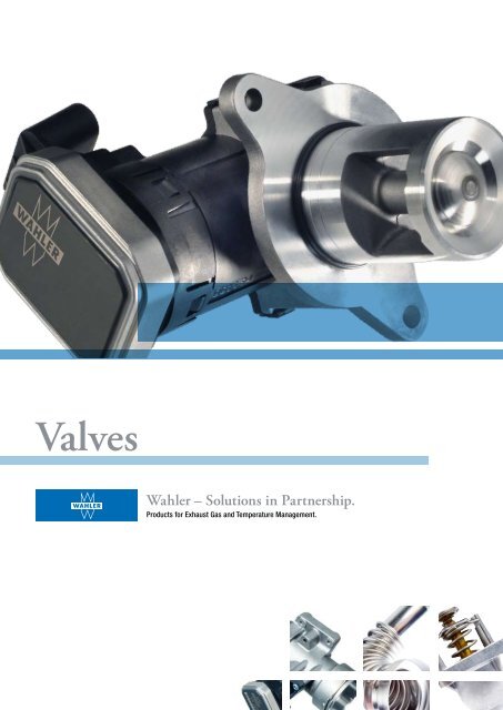
<strong>Valves</strong><br />
<strong>Wahler</strong> – Solutions in Partnership.<br />
Products for Exhaust Gas and Temperature Management.
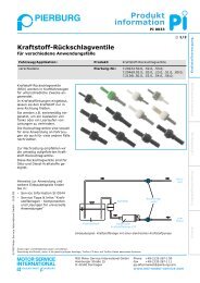
EGR <strong>Co</strong>mponents<br />
Key components for clean engine power<br />
C<br />
EGR pipe<br />
3 EGR cooler<br />
B<br />
EGR pipe (cold)<br />
2 Engine control unit<br />
D<br />
Bypass flap<br />
E<br />
EGR valve<br />
F<br />
EGR pipe (hot)<br />
4 Exhaust system<br />
A<br />
Throttle flap with<br />
mixing chamber<br />
1 Air filter<br />
5 Engine<br />
2 3
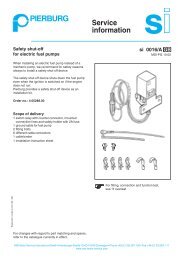
Entwicklung Development der Euro-Normen of standards und der and <strong>Wahler</strong>-AGR-Komponenten<br />
EGR components<br />
Elektrisches Electric EGR flap<br />
AGR-Klappenventil<br />
valve with<br />
mit electronics Elektronik<br />
Pneumatisches Pneumatic<br />
Electric Elektrisches EGR Electric Elektrische throttle Elektrisches Electric rotary Elektrisches Electric EGR Elektrisches Electric EGR<br />
AGR-Ventil EGR valve<br />
AGR-Ventil valve with Drosselklappe flap with AGR-Drehventil<br />
EGR valve with AGR-Ventil valve without AGR-Ventil valve with<br />
mit electronics Elektronik mit electronics Elektronik mit electronics Elektronik ohne electronics<br />
Elektronik<br />
mit DC actuator<br />
DC-Antrieb<br />
1992 1993 1994 1995 1996 1997 1998 1999 2000 2001 2002 2003 2004 2005 2006 2007 2008 2009 2010<br />
Euro I Euro II Euro III Euro IV Euro V<br />
NOx 1000<br />
800 500 250<br />
180<br />
PM<br />
180 80 / 100* 50 25<br />
5<br />
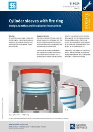
EGR Systems<br />
The combustion under differing operating<br />
conditions of the engine is always kept<br />
within the optimum working range via<br />
respective functions of the engine control<br />
unit and the implementation of EGR<br />
systems.<br />
Values Werte in mg/km<br />
The demands made on driving comfort<br />
and engine power are constantly<br />
increasing. At the same time a growing<br />
awareness of the environment and more<br />
stringent exhaust gas limit values<br />
world-wide demand reduced emissions<br />
of hazardous substances, particularly of<br />
nitric oxide and particle distributions.<br />
EGR for reducing NOx<br />
The most effective method for reducing<br />
the share of nitric oxides (NOx) is<br />
achieved by exhaust gas return (EGR).<br />
Here, the exhaust gas is mixed with the<br />
* mit * With Direkteinspritzung<br />
direct injection<br />
sucked-in ambient air. This leads to a<br />
lower oxygen concentration in the air/fuel<br />
mixture for the same load quantity in the<br />
combustion chamber, and thus to slower<br />
combustion. The subsequently achieved<br />
reduction in the peak combustion<br />
temperatures results in the reduced<br />
formation of nitric oxide.<br />
The reduced combustion temperature<br />
leads to an increase in the particle<br />
distribution in diesel engines. Post-oxidation<br />
of the particles and their complete<br />
burn-out would only take place at high<br />
temperatures. A conflict of objectives with<br />
the technical term ‘Trade-Off’.<br />
The EGR valve enables the quantity of the<br />
recirculated exhaust gas to be regulated.<br />
Depending on the engine temperature, the<br />
exhaust gas can be conducted through<br />
the bypass flap via the EGR cooler, or to<br />
the mixing chamber, uncooled. The throttle<br />
flap in the intake channel allows the<br />
differential pressure to rise and thereby<br />
the EGR quantity to increase.<br />
The figure on the left shows all the EGR<br />
components that complement each<br />
other due to <strong>Wahler</strong>'s close collaboration<br />
with the engine manufacturers to form a<br />
perfectly adapted EGR system. The<br />
implementation of EGR systems in the<br />
engines of the future will continue to<br />
increase, in order to adhere to the<br />
emission standards that are continually<br />
becoming more and more stringent.<br />
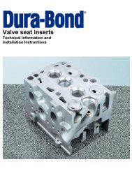
Durchsatzkennlinien<br />
Mass flow characteristics<br />
Partikel, Particle, uncooled ungekühlt<br />
Q [kg/h]<br />
bei at 100 hPa<br />
NOx, ungekühlt uncooled<br />
Partikel, Particle, cooled gekühlt<br />
NOx, gekühlt cooled<br />
>200<br />
120<br />
Klappenventil<br />
Flap valve<br />
Drehventil Rotary valve<br />
Hubventil Poppet valve<br />
Emission<br />
0<br />
10 20 30 40 50 60 70<br />
AGR-Rate EGR rate in [%]<br />
0<br />
0<br />
Hubventil Poppet valve<br />
max. Hub stroke<br />
Flap/Rotary Klappen-/Drehventil valve 90°<br />
s [mm]<br />
ϕ [ ]<br />
‘Trade-Off’ – NOx versus particle emission<br />
Mass flow characteristics of the different valves
EGR Poppet <strong>Valves</strong><br />
Proven in the past and still up-to-date<br />
4 5<br />
Features of the EGR poppet valves<br />
• Application for small to medium EGR rates (passenger cars,<br />
approx. 130 kg/h at 100 hPa and 20°C gas temperatur)<br />
• <strong>Co</strong>ntinuously variable control of the EGR mass flow rate<br />
• Tight closure of the EGR channel during full-load operation<br />
• Fail-safe function in the case of an actuator failure<br />
• Pneumatic or electric actuator<br />
• On-board diagnosis possible with position sensor<br />
• Option – with or without controller<br />
• With/without cooling for use on hot/cold side
<strong>Wahler</strong> was one of the first to realise the<br />
significance of exhaust gas return and<br />
played a decisive role in its development.<br />
Since 1994 we have been producing pneumatic<br />
EGR valves in series and the figures<br />
speak for themselves. Over 10 million<br />
poppet valves have since been regulating<br />
the flow of exhaust gas in the engines of<br />
the most varying manufacturers.<br />
Proven a millionfold<br />
In the case of the poppet valve, the valve<br />
seat is integrated in the housing. It is<br />
closed by a poppet disc with a closely<br />
fitting geometry and thereby has very low<br />
leakage values. The poppet disc itself is<br />
connected to the actuator by a shaft.<br />
Pneumatic poppet valves have a vacuum<br />
actuator with a membrane that controls<br />
the poppet disc. If the vacuum pressure<br />
system should fail, a return spring<br />
ensures that the ‘fail-safe’ position ‘valve<br />
closed’ comes into effect. It similarly<br />
produces a counteracting force and<br />
thereby ensures a linear course of the<br />
characteristic.<br />
Modern actuator<br />
The introduction of the electronic control<br />
units (ECU) for engines gave rise to the<br />
requirement for enabling the EGR valves<br />
to be controlled by the engine software.<br />
An electro-pneumatic transducer<br />
therefore converts the control signals of<br />
the ECU to pneumatic pressure signals.<br />
As a result, the link was established<br />
between mechanics and electronics.<br />
Following the requirements of modern<br />
combustion engines, <strong>Wahler</strong> fitted his<br />
successful poppet valves with an electric<br />
actuator in 1999. The electric poppet<br />
valve ensures short positioning times<br />
and high positioning accuracy of less<br />
than 0.1 mm. The actuation via a rotary<br />
solenoid or a DC actuator enables direct<br />
access of the engine control unit.<br />
Intelligence of its own<br />
A sensor for detecting the valve position<br />
enables real control. This takes place in<br />
the case of the rotary solenoid either via<br />
the engine control unit – like also in the<br />
case of the DC actuator – or via the own<br />
intelligence of the valve. In this case the<br />
engine control unit sends a set value via<br />
a powerless connection, that the valve<br />
holds independently, even in the case of<br />
variable differential pressure on the<br />
poppet.<br />
In addition, the sensor enables the<br />
increasingly important OBD function.<br />
Diagnostic data can be recorded by the<br />
control unit and stored for later error<br />
diagnosis.<br />
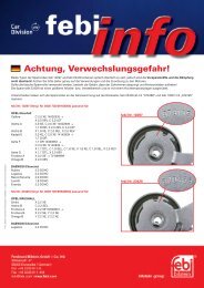
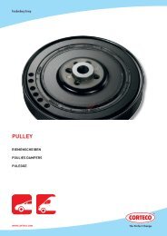
stroke<br />
Vergleich <strong>Co</strong>mparison Aktuatortypen of actuator types<br />
elektrisch electric<br />
pneumatisch pneumatic<br />
temperature<br />
Pneumatic EGR valve with<br />
throttle flap<br />
Hysteresis-free control for the electric<br />
poppet valve<br />
Poppet valve with DC actuator
EGR Rotary and Flap <strong>Valves</strong><br />
<strong>Co</strong>ntinuously variable from low to high mass flow rates<br />
6 7<br />
EGR flap valves at a glance<br />
• Application for high EGR rates (medium and<br />
large-sized engines for commercial vehicles)<br />
• <strong>Co</strong>ntinuously variable control of the<br />
EGR mass flow rate<br />
• Closure of the EGR channel during<br />
full-load operation<br />
• Fail-safe function in the case of an<br />
actuator failure<br />
• On-board diagnosis with position sensor
Electric rotary valve<br />
For engines with a displacement of<br />
2.5 - 9 litres (large passengers cars to<br />
medium-sized commercial vehicles) the<br />
rotary valve takes over both the exact<br />
and continuously variable control of small<br />
exhaust gas flows during full-load<br />
oper ation as well as the throughput of<br />
large flow rates during partial load<br />
operation.<br />
With the increasing complexity of modern<br />
combustion engines, the demands made<br />
on EGR components change. Due to the<br />
differing laws on emissions, different<br />
requirements result world-wide. New<br />
valves have been developed as a result<br />
of increasing exhaust counter pressure<br />
and variable differential pressure on the<br />
valve, the demand for continuously<br />
variable control of large flow rates and an<br />
exact control of small quantities of<br />
exhaust gas.<br />
In this case, the valve disc does not<br />
operate against the exhaust pressure like<br />
the poppet valve but, in a rotary movement,<br />
clears the window openings for the<br />
exhaust gas to flow through. The special<br />
contour of these openings enables the<br />
said requirements for controlling the<br />
exhaust gas flow to be fulfilled.<br />
Electric flap valve<br />
The flap valve fulfils the requirement for<br />
high exhaust gas return rates. These are<br />
required for large volume engines in<br />
heavy commercial vehicles. This valve is<br />
outstanding due to its short positioning<br />
times and its exact and continuously<br />
variable regulation of large flow rates.<br />
Appropriately adapted housing and flap<br />
geometries also ensure low leakage<br />
values.<br />
Electric EGR rotary valve<br />
Cross-section: electric<br />
EGR flap valve<br />
Cross-section: electric<br />
EGR rotary valve<br />
Short introduction of the EGR rotary valves<br />
• Application for medium EGR rates (passenger<br />
cars and medium-sized commercial vehicles)<br />
• <strong>Co</strong>ntinuously variable control of the EGR mass flow rate<br />
• Exact control of low return rates<br />
• Closure of the EGR channel during full-load operation<br />
• Fail-safe function in the case of an actuator failure<br />
• On-board diagnosis possible with position sensor<br />
• Option – with or without electronics<br />
• Option – with or without cooling
EGR Bypass Flap and Actuator<br />
Pneumatics with a groundbreaking task<br />
8 9<br />
Features of the EGR bypass flap<br />
• <strong>Co</strong>nducts exhaust gas through<br />
the EGR cooler or bypass channel<br />
• Installation possible before or after<br />
the EGR cooler<br />
• Drive via pneumatic actuator<br />
• Fail-safe function in the case of an<br />
actuator failure<br />
• On-board diagnosis with position sensor<br />
• Option – with or without cooling
installation circumstances, the mechanics<br />
of these bypass flaps has to be<br />
protected by a suitable liquid cooling.<br />
For a high temperature-resistant variant<br />
without a liquid cooling, investment<br />
casting or steel casting is used. More<br />
recent developments use deep-draw<br />
housings made of stainless steel.<br />
After the quantity of exhaust gas actually<br />
needed has branched off via the EGR<br />
valve and has been conducted into the<br />
recirculation system, the further path of<br />
the EGR flow has to be determined, this<br />
depending on the engine and exhaust<br />
gas temperature. A bypass flap determines<br />
whether it should flow through the<br />
EGR cooler or through the bypass<br />
channel.<br />
Each flap is different<br />
The design of the flap has to be adapted<br />
to the respective cooler used and thus<br />
there are different designs and housing<br />
materials. For reasons of weight, the<br />
housing of a conventional bypass flap, is<br />
mostly made of aluminium die-cast.<br />
Depending on the application and<br />
Universal actuator<br />
The bypass flap is commonly activated<br />
via a pneumatic actuator. These versatile<br />
actuators fulfil various other functions on<br />
different engine components. Here, the<br />
membrane of a vacuum actuator is<br />
directly linked to a driving rod that can<br />
operate flaps for sound modulation in<br />
turbocharger applications, or for diesel<br />
particle filter regeneration (DPF) etc.<br />
Fitted with a position sensor, the<br />
actuator can also be used for applications<br />
where it is necessary to detect the<br />
stroke of the actuator (e.g. sound flap,<br />
turbocharger).<br />
These mechanical components with their<br />
versatile applications are integrated with<br />
electronic control circuits by the use of<br />
an electro-pneumatic transducer.<br />
Pneumatic actuator<br />
Profile of the pneumatic actuator<br />
• Takes over different adjustment<br />
functions on the engine<br />
• Membrane produces a lifting movement<br />
• High actuating force in proportion to<br />
weight and installation space<br />
• Fail-safe function in the case of a<br />
pressure system failure<br />
Cross-section of bypass flap<br />
Driving rod of the actuator
Throttle Flap<br />
The gateway from the intake channel to the engine<br />
10 11<br />
Functions of the throttle flap<br />
• Mostly integrated in the mixing chamber<br />
• In connection with the EGR valve, it controls the<br />
EGR rate by setting a defined differential pressure<br />
• <strong>Co</strong>ntrols the mass flow in the regeneration mode of<br />
the diesel particle filter<br />
• Tight closure prevents the shut-down stroke when<br />
the engine is switched off<br />
• On-board diagnosis with position sensor<br />
• Fail-safe function in the case of an actuator failure
As a rule, the throttle flap is mostly integrated<br />
in the mixing chamber. Originally<br />
its scope of application was restricted to<br />
throttling the intake air in diesel engines<br />
and – by increasing the differential pressure<br />
– thereby increasing the amount of<br />
the returned exhaust gas. The demands<br />
for control precision and manipulating<br />
speed were comparably low.<br />
Fitting accuracy<br />
Today’s diesel engines however, have to<br />
be operated with a defined air/fuel<br />
mixture, similar to gasoline engines. The<br />
modern throttle flaps take over important<br />
functions, e.g. the control of the incoming<br />
amount of air in the mode of the<br />
diesel particle filter regeneration. <strong>Co</strong>mplete<br />
closure of the throttle flap enables<br />
the temperature in the particle filter to<br />
increase until burn-off. The tight closure<br />
of the throttle flap is also beneficial when<br />
turning off the diesel engine. By interrupting<br />
the air-mass flow the engine only<br />
sucks in air at a very low density and<br />
stops without juddering. This contributes<br />
towards improving comfort, especially<br />
where large-volume engines in commercial<br />
vehicles are concerned.<br />
Performance<br />
High performance requires a progressive<br />
flow characteristic shortly before the<br />
throttle flap is in the closing position. If<br />
the angle for the closed flap is chosen<br />
at almost 90°, the flow characteristic is<br />
flat, as required. At smaller angles the<br />
characteristic is steeper and the control<br />
precision is reduced, as shown in the<br />
figure below.<br />
Stable positioning<br />
Besides integrating the algorithms for<br />
controlling the flap position completely<br />
with the engine electronics, the throttle<br />
flap can also be fitted with its own<br />
intelligence. This means the set value<br />
given by the engine control unit can be<br />
maintained even at variable differential<br />
pressures on the flap.<br />
intake Frischluftdurchsatz air throughput [kg/h]<br />
500<br />
400<br />
300<br />
200<br />
100<br />
Flap Klappe B at B 10 bei hPa 10 hPa<br />
Flap Klappe A at A 10 bei hPa 10 hPa<br />
Endwinkel angle 75°<br />
Endwinkel angle 70°<br />
0<br />
0°<br />
10° 20°<br />
30° 40°<br />
50° 60° 70° 80°<br />
Öffnungswinkel opening angle [ °]<br />
Cross-section – throttle flap Adapted throttle flap with mixing chamber Mass flow characteristics of different flaps
EGR Systems<br />
Function and form – perfectly combined<br />
12 13<br />
Profile of the EGR system<br />
• <strong>Co</strong>nsists of co-ordinated components<br />
• Reduces the peak combustion temperature<br />
for reducing exhaust emissions<br />
• The most effective method for reducing<br />
the NOx emission<br />
• More complex engines and more stringent<br />
environmental laws increase the demands<br />
• One engineering partner – less co-ordination<br />
effort as well as lower prices
Bypass flap<br />
(drop-in)<br />
Support housing<br />
<strong>Co</strong>mpetent development partner<br />
The mere supply of isolated products is<br />
increasingly giving way to the joint development<br />
of sophisticated EGR components.<br />
<strong>Wahler</strong> is a long-standing, competent<br />
development partner for many<br />
automobile manufacturers and is in daily<br />
contact with the engine developers. Due<br />
to this close co-operation, well-adapted<br />
and efficient solutions result and signify<br />
a continuous improvement in engine<br />
technology.<br />
Actuator<br />
EGR valves<br />
System solution including various<br />
components for exhaust gas return<br />
The engine concepts and thus also the<br />
concepts for exhaust gas return are<br />
undergoing continual further development.<br />
The individual components have<br />
to be adapted mutually in an optimum<br />
way, in order to fulfil the high demands<br />
for control precision and speed.<br />
The actuators of the future for example,<br />
will have a considerably smaller overall<br />
dimension for the same, or higher power<br />
density. EGR components are being<br />
fitted with sensors to an increasing extent<br />
and thus have an analogue or digital interface<br />
that enables them to be integrated<br />
in the engine control.<br />
Only in this way shall we, together with<br />
our customers, be able to face the<br />
demands of the current engine development<br />
and the future legal requirements.<br />
Tradition and innovation<br />
The development of new solutions is based<br />
on experience gained from previous<br />
projects. The development in the engine<br />
sector is progressing ever faster and<br />
<strong>Wahler</strong> is paving the way by modularising<br />
its products. New, decisive components for<br />
exhaust gas return thus develop from a<br />
successful mix of tradition and innovation.<br />
This reduces the time spent on development<br />
and provides new solutions based on<br />
proven concepts.<br />
Pressure stress on the<br />
housing screw connections<br />
Specialists with one aim –<br />
customer satisfaction<br />
<strong>Co</strong>mpact EGR system
<strong>Co</strong>ntinuous Improvements<br />
Experience gained today are basis for the requirements of tomorrow<br />
Research and development at <strong>Wahler</strong><br />
• A competent development partner for<br />
our customers<br />
• Modern development methods<br />
• Serial testing of all the components inhouse<br />
• <strong>Co</strong>ntinued development of automobile<br />
technology through innovation<br />
14 15
At <strong>Wahler</strong> the product engineering<br />
process is determined by the quality<br />
assurance specifications of the automotive<br />
industry (VDA standards, QS 9000,<br />
DIN ISO 16949) and based on the<br />
progressive methods of APQP (Advanced<br />
Process Quality Planning).<br />
Different aspects<br />
A process-oriented structural organisation<br />
accompanies the development<br />
process from the initial idea through to<br />
the readiness for series production.<br />
Specialists from the Development,<br />
Production, Quality Assurance, Purchasing,<br />
Sales and Logistics already<br />
contribute their experience at an early<br />
phase in the new product’s development.<br />
Modern methods<br />
The product development implements<br />
established methods and tools such as<br />
Finite Element Method (FEM), <strong>Co</strong>mputational<br />
Fluid Dynamics (CFD), Failure<br />
Modes and Effects Analysis (FMEA) and<br />
prototype construction. Particularly in the<br />
last point, <strong>Wahler</strong> is a convincing partner<br />
with its short response times and its fast<br />
availability of prototypes. The high<br />
flexibility of our medium-sized company<br />
helps to reduce the overall development<br />
time considerably.<br />
At our company's own test benches the<br />
prototypes are put to the acid test and<br />
at our engine test bench, for example,<br />
they can prove their suitability for daily<br />
use.<br />
Once a product has reached the readiness<br />
stage for serial production, it is<br />
produced at modern, interlinked<br />
production lines. During production each<br />
valve is assigned a profile in which the<br />
origin and the testing parameters of<br />
each finally assembled product are<br />
recorded. This enables complete<br />
retracing of possible faults and ensures a<br />
consistent feedback of information from<br />
the quality assurance to the further<br />
product development.<br />
Outlook<br />
In the future, exhaust gas return in diesel<br />
engines will also be taking place during<br />
full-load operation and will thus involve<br />
the entire operating range of the engine.<br />
In the same way, the reduction of the<br />
NOx emissions on a stratified-charge<br />
direct fuel injected gasoline engine calls<br />
for external EGR rates. As a result, the<br />
requirements for temperature resistance<br />
and solidity of the EGR components will<br />
rise. At the same time, the exhaust gas<br />
flow rate to be controlled will increase.<br />
This trend will demand new solutions for<br />
the housings, components and gaskets<br />
of the EGR components.<br />
Fast, accurate and yet low-cost actuators<br />
will make their entrance, just as the<br />
assembly of individual components in a<br />
single unit makes up for the increasingly<br />
restricted installation conditions.<br />
The growth in the application of EGR<br />
systems will be promoted by new engine<br />
concepts and more stringent emission<br />
standards. With its wide experience<br />
gained over many years, its motivated<br />
and highly qualified employees and its<br />
modern equipment, <strong>Wahler</strong> is optimally<br />
geared to this trend.<br />
Visualisation of flow and<br />
temperature distribution<br />
Examination of vibration stress<br />
Test under real conditions at the<br />
engine test bench
<strong>Gustav</strong> <strong>Wahler</strong> <strong>GmbH</strong> u. <strong>Co</strong>. <strong>KG</strong><br />
Hindenburgstrasse 146<br />
73730 Esslingen<br />
Germany<br />
Phone: +49 711 3152-0<br />
Fax: +49 711 3152-210<br />
Email: info@wahler.de<br />
Internet: www.wahler.de