Cylinder sleeves with fire ring - Design, function ... - Wilmink Group
Cylinder sleeves with fire ring - Design, function ... - Wilmink Group
Cylinder sleeves with fire ring - Design, function ... - Wilmink Group

You also want an ePaper? Increase the reach of your titles
YUMPU automatically turns print PDFs into web optimized ePapers that Google loves.
SI 0024<br />
For technical personnel only!<br />
Page 1/4<br />
<strong>Cylinder</strong> <strong>sleeves</strong> <strong>with</strong> <strong>fire</strong> <strong>ring</strong><br />
<strong>Design</strong>, <strong>function</strong> and installation instructions<br />
S E R V I C E<br />
I N F O R M A T I O N<br />
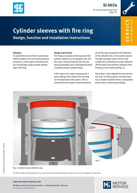
Situation<br />
To extend the service life of commercial<br />
vehicle engines and cut harmful exhaust<br />
emissions, some engine manufacturers<br />
are increasingly using cylinder <strong>sleeves</strong><br />
<strong>with</strong> a <strong>fire</strong> <strong>ring</strong>.<br />
<strong>Design</strong> and <strong>function</strong><br />
Fire <strong>ring</strong>s are placed at the top end of the<br />
cylinder <strong>sleeves</strong> in a rectangular slot. The<br />
<strong>fire</strong> <strong>ring</strong> is loosely inserted into the slot<br />
du<strong>ring</strong> assembly and is subsequently held<br />
in position by the cylinder head.<br />
of the <strong>fire</strong> <strong>ring</strong> compared to the diameter<br />
of the cylinder bore. As the piston passes<br />
through top dead centre, the <strong>fire</strong> <strong>ring</strong><br />
scrapes the unwanted oil carbon deposits<br />
off the piston and prevents deposits from<br />
forming on the head land (Fig. 2).<br />
A <strong>fire</strong> <strong>ring</strong> or oil scraper <strong>ring</strong> prevents a<br />
hard coating of oil carbon from forming<br />
on the head land of the piston. This is<br />
achieved by the smaller internal diameter<br />
The piston is also adapted for the use of a<br />
<strong>fire</strong> <strong>ring</strong>. For this purpose, the head land<br />
has a smaller diameter than a comparable<br />
piston <strong>with</strong> a conventional design.<br />
© MS Motor Service International GmbH – 0310 EN<br />
Fig. 1: <strong>Cylinder</strong> sleeve <strong>with</strong> <strong>fire</strong> <strong>ring</strong><br />
Fig. 2<br />
The right of changes and deviating pictures is reserved. For exact details about applications, please refer to our current catalogue / CD / online shop.<br />
www.ms-motor-service.com<br />
MS Motor Service International GmbH · 74196 Neuenstadt · Germany<br />
KOLBENSCHMIDT PIERBURG GROUP
SI 0024<br />
For technical personnel only!<br />
Page 2/4<br />
Problem and solution<br />
On cylinder <strong>sleeves</strong> <strong>with</strong> no <strong>fire</strong> <strong>ring</strong>, if the<br />
engine is used in unfavourable conditions<br />
a hard layer of oil carbon can form on the<br />
head land of the piston (Fig. 4, left).<br />
Unfavourable conditions include:<br />
• Frequent short distance driving<br />
• Frequent idling<br />
• Operation of the engine <strong>with</strong><br />
unsatisfactory fuel and oil qualities<br />
• Lack of vehicle maintenance<br />
On cylinder <strong>sleeves</strong> <strong>with</strong> no <strong>fire</strong> <strong>ring</strong>,<br />
an oil carbon layer on the head land<br />
of the piston leads to abrasive wear<br />
after a relatively short operating time<br />
(Fig. 4, right).<br />
This unwanted, premature wear on the<br />
cylinder <strong>sleeves</strong> – combined <strong>with</strong> excessive<br />
oil consumption – can be prevented<br />
by using cylinder <strong>sleeves</strong><br />
<strong>with</strong> <strong>fire</strong> <strong>ring</strong>.<br />
Fig. 3: <strong>Cylinder</strong> sleeve <strong>with</strong> <strong>fire</strong> <strong>ring</strong><br />
© MS Motor Service International GmbH – 0310 EN<br />
Fig. 4: Oil carbon layer on head land and abrasive wear to cylinder wall<br />
www.ms-motor-service.com<br />
MS Motor Service International GmbH · 74196 Neuenstadt · Germany<br />
KOLBENSCHMIDT PIERBURG GROUP
SI 0024<br />
For technical personnel only!<br />
Page 3/4<br />
Removing the cylinder sleeve<br />
For the piston to be removed, the <strong>fire</strong> <strong>ring</strong><br />
must first be removed from the cylinder<br />
sleeve. For used cylinder <strong>sleeves</strong>, this<br />
cannot immediately be done manually.<br />
Deposits between the <strong>fire</strong> <strong>ring</strong> and the<br />
cylinder sleeve cause the <strong>fire</strong> <strong>ring</strong> to<br />
be tightly stuck in its mounting. When<br />
removing defective cylinder <strong>sleeves</strong>, the<br />
<strong>fire</strong> <strong>ring</strong> can be destroyed using a chisel<br />
worked between the <strong>fire</strong> <strong>ring</strong> and the<br />
cylinder sleeve (Fig. 5).<br />
A used piston <strong>ring</strong>, <strong>with</strong> a diameter<br />
corresponding to that of the cylinder, is<br />
then inserted into the cylinder below the<br />
<strong>fire</strong> <strong>ring</strong> (Fig. 6).<br />
Rotating the crankshaft causes the piston<br />
to move the <strong>fire</strong> <strong>ring</strong> out of the cylinder<br />
sleeve (Fig. 8). To prevent the piston <strong>ring</strong><br />
used as a removal tool from becoming<br />
compressed and sliding over the <strong>fire</strong> <strong>ring</strong>,<br />
the joint gap must be bridged <strong>with</strong> a slip<br />
gauge of appropriate thickness while<br />
sliding out the <strong>fire</strong> <strong>ring</strong> (Fig. 7).<br />
Fig. 5<br />
If the cylinder sleeve and the <strong>fire</strong> <strong>ring</strong> are<br />
to be reused, the piston is moved slightly<br />
downwards by rotating the crankshaft, so<br />
that the <strong>fire</strong> <strong>ring</strong> is accessible.<br />
If only the piston is to be removed, the<br />
cylinder sleeve must be fixed in place, i.e.<br />
pressed onto its mounting. Otherwise,<br />
the piston will slide the <strong>fire</strong> <strong>ring</strong> and the<br />
cylinder sleeve out of the engine block.<br />
Fig. 6<br />
© MS Motor Service International GmbH – 0310 EN<br />
Fig. 7<br />
Fig. 8<br />
www.ms-motor-service.com<br />
MS Motor Service International GmbH · 74196 Neuenstadt · Germany<br />
KOLBENSCHMIDT PIERBURG GROUP
SI 0024<br />
For technical personnel only!<br />
Page 4/4<br />
Installation of cylinder sleeve<br />
The cylinder sleeve is first inserted into<br />
the engine block <strong>with</strong>out a <strong>fire</strong> <strong>ring</strong>. The<br />
piston and the con rod are then inserted<br />
into the cylinder and attached to the<br />
crankshaft as specified. When inserting<br />
the piston, it is essential to ensure that<br />
the piston <strong>ring</strong> tensioning strap is pushed<br />
sufficiently far into the <strong>fire</strong> <strong>ring</strong> slot<br />
(Fig. 10). This makes sure that the piston<br />
<strong>ring</strong>s do not rebound into the <strong>fire</strong> <strong>ring</strong> slot<br />
and suffer damage as a result. After<br />
installing the piston, the <strong>fire</strong> <strong>ring</strong> is placed<br />
in the slot manually. With used parts, a<br />
slightly stiff <strong>fire</strong> <strong>ring</strong> can be carefully<br />
knocked into the cylinder sleeve using<br />
a hammer and a block of wood (Fig. 9).<br />
Fig. 9<br />
Installation and usage instructions<br />
• Pistons and cylinder <strong>sleeves</strong> <strong>with</strong> <strong>fire</strong><br />
<strong>ring</strong> should be sold as a set to prevent<br />
incorrect combinations of parts and to<br />
avoid clearance problems.<br />
• When replacing only the piston,<br />
it is essential to ensure that it is<br />
intended for use <strong>with</strong> <strong>fire</strong> <strong>ring</strong> (if<br />
necessary compare the diameter<br />
of the head land <strong>with</strong> the old part).<br />
• When replacing only the cylinder<br />
sleeve, it is essential to ensure<br />
that the height of the <strong>fire</strong> <strong>ring</strong><br />
is less than the height of the head<br />
land on the piston.<br />
• The <strong>fire</strong> <strong>ring</strong> may not be left out. It must<br />
always be installed so that the engine<br />
will achieve its specified compression<br />
and power.<br />
• Fire <strong>ring</strong>s are produced symmetrically,<br />
i.e. the <strong>ring</strong> does not have a particular<br />
installation direction.<br />
• When reworking on the engine block<br />
sealing surface, as well as complying<br />
<strong>with</strong> or setting the specified piston<br />
projection, it is also essential to<br />
ensure that the first compression <strong>ring</strong><br />
cannot collide <strong>with</strong> the <strong>fire</strong> <strong>ring</strong>.<br />
• Fire <strong>ring</strong>s are not honed on the internal<br />
diameter.<br />
• Do not retrofit cylinder <strong>sleeves</strong> <strong>with</strong><br />
<strong>fire</strong> <strong>ring</strong>s if they are not approved<br />
by the manufacturer.<br />
Delivery information<br />
KS cylinder <strong>sleeves</strong> are always supplied<br />
as a complete kit, i.e. <strong>with</strong> <strong>fire</strong> <strong>ring</strong> and<br />
sealing <strong>ring</strong>s. Fire <strong>ring</strong>s are not available<br />
individually as spare parts.<br />
© MS Motor Service International GmbH – 0310 EN<br />
Fig. 10<br />
www.ms-motor-service.com<br />
MS Motor Service International GmbH · 74196 Neuenstadt · Germany<br />
KOLBENSCHMIDT PIERBURG GROUP