Dura-Bond Valve Seat Inserts Info. - Dura-Bond Bearing
Dura-Bond Valve Seat Inserts Info. - Dura-Bond Bearing
Dura-Bond Valve Seat Inserts Info. - Dura-Bond Bearing
- No tags were found...

Create successful ePaper yourself
Turn your PDF publications into a flip-book with our unique Google optimized e-Paper software.
<strong>Valve</strong> seat inserts<br />
Technical <strong>Info</strong>rmation and<br />
Installation Instructions
Index<br />
Chapter 1: Introduction<br />
1.1 <strong>Valve</strong> seat installation<br />
1.2 Machining practices<br />
Chapter 2: Cutting valve seat inserts and<br />
counter bores<br />
2.1 Removal of valve<br />
seats and cutting<br />
of seat pocket<br />
counter bores<br />
Chapter 3:Installation<br />
3.1 Inserting the<br />
valve seats<br />
3.2 Cutting the<br />
seating surface<br />
3.3 Using a<br />
cutting machine<br />
3.4 Using a<br />
grinding machine<br />
3.5 Checking the<br />
final product<br />
Chapter 4: <strong>Dura</strong>-<strong>Bond</strong> valve seat inserts<br />
4.1 <strong>Valve</strong> seat inserts<br />
Materials<br />
4.2 30000 / 70000 Series<br />
4.3 Overview<br />
2
Chapter 1:<br />
Introduction<br />
1.1 <strong>Valve</strong> seat installation<br />
<strong>Valve</strong> seat installation and refitting is<br />
only one of many operations necessary<br />
for the professional rebuilding<br />
or reconditioning of a cylinder head.<br />
Successful cylinder head remanufacturing<br />
requires that these reconditioning<br />
operations be done in the<br />
correct sequence.<br />
<strong>Valve</strong> seat installation and refitting<br />
can only be successfully accomplished<br />
after the following operations<br />
have been completed.<br />
• Through cleaning, inspection<br />
and any failure analysis<br />
• Measure and record each assembled<br />
valve stem height and<br />
valve head protrusion<br />
• Straightening of the cylinder<br />
head and milling/grinding of the<br />
firing deck and all other mating<br />
surfaces<br />
• All valve guides must be renewed<br />
or refitted and be within<br />
original factory specifications<br />
The cylinder head must be dimensionally<br />
and geometrically within<br />
original factory specifications. The<br />
cylinder head thickness, valve guide<br />
clearances, concentricity, and<br />
perpendicularity must be correct.<br />
There should be no warping, twisting,<br />
or any type of misalignment<br />
of any part of the cylinder head.<br />
Sometimes you may lightly touch<br />
up the valve face and valve seat<br />
mating surface without putting the<br />
valve geometry out of factory specification<br />
but most of the modern<br />
multi-valve aluminum cylinder<br />
heads will require new inserts be<br />
installed to maintain correct valve<br />
train geometry.<br />
Only new valves or valves which<br />
have been reconditioned and are<br />
within original factory specification<br />
must be used. All valve springs<br />
must be inspected and must meet<br />
all original factory specifications or<br />
be replaced.<br />
As it relates to valve seats, there<br />
are three types of cylinder heads:<br />
• Cast iron cylinder heads with<br />
removable valve seat inserts<br />
• Cast iron cylinder heads with<br />
integral hardened valve seat<br />
areas<br />
• Aluminum cylinder heads with<br />
removable valve seat inserts<br />
You must replace the old valve seat<br />
insert or refit the integral hardened<br />
valve seat area with a new valve<br />
seat insert if:<br />
• The cylinder head required<br />
straightening before resurfacing.<br />
• Any welding had to be done on<br />
the cylinder head.<br />
• The cylinder head is aluminum<br />
and was cleaned in a heating<br />
oven.<br />
• The valve seating (mating) surface<br />
has receded beyond factory<br />
specifications.<br />
• The valve seating (mating) surface<br />
is too wide and recutting or<br />
regrinding would lower the seat<br />
beyond factory specifications.<br />
• The integral seat of a cast iron<br />
head has been ground before.<br />
(The depth of the hardened cylinder<br />
head material used for the<br />
seating area will be too shallow<br />
to allow a second grinding)<br />
• There is any evidence that the<br />
valve seat insert is loose in the<br />
counter bore pocket, or does not<br />
have adequate interference fit.<br />
• There is any evidence of corrosion<br />
of the cylinder head material<br />
around the outside diameter of<br />
the valve seat insert.<br />
• There is any evidence that the<br />
seat has any cracking, burning,<br />
pitting or fissures.<br />
• The fuel type being used is going<br />
to be changed. This will require a<br />
higher duty range valve seat for<br />
better durability.
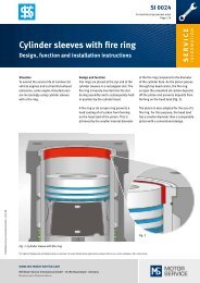
1.2 Machining practices<br />
Although many factors contribute<br />
to the successful machining of<br />
valve seats. Here are several key<br />
conditions that are required to<br />
achieve good results.<br />
• By far the most important is to<br />
have properly sharpened tools<br />
and properly dressed grinding<br />
stones.<br />
• Keep your tooling setup as<br />
”short and tight” as possible to<br />
assure rigidity (Picture 1). The<br />
less deflection in the tooling the<br />
more accurate the dimensions<br />
of the cut and the greater concentricity.<br />
• Keep your clamping arms and<br />
fixtures in good repair for correct<br />
gripping.<br />
• Make sure not to distort or put a<br />
twist into the cylinder head when<br />
clamping to a fixed rail cylinder<br />
head holding fixture (Picture 2).<br />
• Use the correct size pilots, which<br />
must be straight.<br />
• Use the correct spindle speeds<br />
and feeds.<br />
Picture 1<br />
Picture 2
Chapter 2: Cutting valve seat inserts and<br />
counter bores<br />
2.1 Removal of valve seats and<br />
cutting of seat pocket counter<br />
bores<br />
Replacing valve seats in heads with<br />
removable seat inserts can be done<br />
in several ways, but the method we<br />
recommend is to use a cutter slightly<br />
smaller than the outside diameter<br />
of the existing valve seat insert and<br />
cut the old seat out (Picture 3). Stop<br />
cutting just as the old seat insert<br />
begins to rotate. The thin wall of the<br />
old valve seat insert can now be easily<br />
removed (Picture 4).<br />
Some machinist will install a new<br />
insert in the existing seat pocket<br />
without recutting the counter bore.<br />
Although this method can be used<br />
on some large cast iron cylinder<br />
heads which are thick walled, it is<br />
not a recommended procedure for<br />
most automotive or ”light pattern”<br />
cylinder heads. It is much better<br />
to cut a new seat insert counter<br />
bore for better valve life and valve<br />
seat insert retention in the cylinder<br />
head (Picture 5). This will also insure<br />
concentricity and perpendicularity<br />
with the valve guide and will<br />
provide a fresh metal surface for<br />
better heat transfer (see our recommended<br />
interference fit chart for the<br />
correct outside diameter).<br />
Picture 3 - Cutting valve seat inserts<br />
Picture 4 - Removing the thin wall of the<br />
old valve seat insert<br />
Picture 5 - Cutting the counter bore<br />
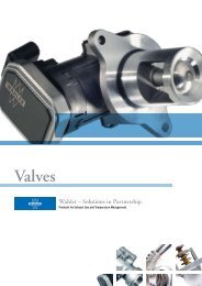
When machining the seat pocket<br />
counter bore in a cast iron cylinder<br />
head we recommend a cutting<br />
speed of 100 to 250 RPM with no<br />
cutting oil. When cutting a seat<br />
pocket counter bore in aluminum<br />
cylinder heads we recommend<br />
using a cutting oil and a spindle<br />
speed of 400 to 600 RPM.<br />
<strong>Dura</strong><strong>Bond</strong> recommends the following press fittings:<br />
Outer diameter valve seats inserts Material cylinder head cast iron Material cylinder head aluminium<br />
[inch] [mm] [inch] [mm] [inch] [mm]<br />
0.7874 - 1.1811 20 - 30 0.0031 0,08 0.0047 0,12<br />
1.1811 - 1.5748 30 - 40 0.0043 0,11 0.0059 0,15<br />
1.5748 - 1.9685 40 - 50 0.0051 0,13 0.0071 0,18<br />
1.9685 - 2.3622 50 - 60 0.0063 0,16 0.0079 0,20<br />
2.3622 - 2.7559 60 - 70 0.0071 0,18 0.0087 0,22<br />
5
Replacing valve seats in cylinder<br />
heads with integral seats will require<br />
a new seat pocket counter bore to<br />
be cut. The approximate outside diameter<br />
for the replacement seat is.100”<br />
(2,5 mm) larger than the valve head<br />
diameter. The inside diameter of the<br />
replacement seat is approximately.100”<br />
(2,5 mm) smaller than the<br />
valve head diameter. The depth is<br />
usually .188” to .250” (4,7 – 6,4 mm).<br />
These sizes are guidelines only.<br />
0.1“<br />
2,5 mm<br />
0.1“<br />
2,5mm<br />
0.188 - 0.25“<br />
4,7 - 6,4 mm<br />
Many of the newer cylinders do not<br />
have the room to install seats with<br />
OD’s larger than the OD of the valve<br />
(see our recommended interference<br />
fit chart for the correct outside diameter).<br />
All counter bores must be concentric<br />
with the valve guide, have a<br />
straight wall, flat bottom and be within<br />
.0005” (0,013 mm) of correct<br />
size and be round.<br />
6
Chapter 3:<br />
Installation<br />
3.1 Inserting the valve seats<br />
Before pressing in the new valve<br />
seat insert please be sure:<br />
• Verify that the valve seat dimensional<br />
measurements are correct<br />
• Verify the counter bore measurements<br />
are correct<br />
• Make sure there are no chips or<br />
debris in the counter bore<br />
• Use a seat installation tool to<br />
insure that the valve seat is inserted<br />
squarely into the counter<br />
bore pocket (Picture 6).<br />
• Use a flat and square seat<br />
driver tool whose size is just<br />
slightly smaller than the outside<br />
diameter of the valve seat insert<br />
(Picture 7).<br />
• Use a correct size pilot for the<br />
valve guide, when using this<br />
valve seat driving tool.<br />
For <strong>Dura</strong>-<strong>Bond</strong> valve seat inserts:<br />
• Insert the valve seat with the<br />
.radius side down.<br />
• Because of the smooth radius<br />
on the bottom outside edge<br />
and the compressive “spring<br />
action” of the material, shrinking<br />
of the seat using liquid<br />
Picture 7<br />
nitrogen -and heating the cylinder<br />
head is not necessary<br />
rprior to insertion the cylinder<br />
head.<br />
Picture 6<br />
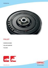
Less force required - less chance<br />
of damaging seat counter bore.<br />
chrome alloy<br />
nickel alloy<br />
cobalt alloy<br />
insertion force required to install<br />
into cylinderhead [%]<br />
cast iron<br />
30000 Series<br />
70000 Series<br />
valve seat material
3.2 Cutting the seating surface<br />
Check the engine specification<br />
manual for the correct assembled<br />
valve height, valve protrusion, seat<br />
angles, seat widths and any other<br />
special seat requirements. These<br />
factory specifications are important<br />
to maintain the correct valve lash,<br />
3.3 Using a cutting machine<br />
(Picture 8)<br />
• Select a cutter profile matching<br />
the original factory valve seat.<br />
The top and bottom relief angles,<br />
and the seating surface width and<br />
angle must match the design<br />
called for by the original engine<br />
manufacture for the valve train<br />
geometry to be correct.<br />
• Select the type and grade of carbide<br />
best suited for the hardness<br />
of the valve seat being machined.<br />
• Make sure that the tool is sharp<br />
and has the correct rake angles<br />
and relief angles.<br />
• A 5-degree cutting rake angle<br />
with an 11-degree relief or clearance<br />
angle is generally found<br />
to be best for valve seats up to<br />
1.250” (31,8 mm) in diameter.<br />
compression ratios, clearances between<br />
valves and pistons, and the<br />
general overall valve train geometry.<br />
Machining and assembling the cylinder<br />
head to the original manufactures<br />
specifications is critical for the<br />
correct operation of the engine.<br />
• A 3-degree cutting rake angle<br />
with a 7-degree relief or clearance<br />
angle is generally found to<br />
be best for cutting valve seats<br />
larger than 1.250” ( 31,8 mm) in<br />
diameter.<br />
• Select the correct spindle<br />
speed for the type of seat being<br />
cut.<br />
• A spindle speed of 150 to 450<br />
RPM is generally a good speed<br />
for cutting the valve seat insert<br />
less than 1.500” (38,0 mm) in<br />
diameter.<br />
• A spindle speed of 100 to<br />
250 RPM works best for seats<br />
larger than 1.500” (38,0 mm)<br />
in diameter.<br />
• <strong>Dura</strong>-<strong>Bond</strong> finds that most people<br />
who have the drill press<br />
style of machine, like the 50 -<br />
100 RPM<br />
• Set the cutter bit to the correct<br />
size for the valve being used<br />
according to the factory repair<br />
manual.<br />
• Cut the seat depth to match the<br />
correct assembled valve height.<br />
Outer Diameter valve seat insert Tool RPM<br />
[inch] [mm] relief angle cutting angle [1/min]<br />
< 1.250 < 31,8 11° 5 ° 150 - 450<br />
> 1.250 > 31,8 7 ° 3 ° 150 - 450<br />
< 1.500 < 38,0 7 ° 3 ° 150 - 450<br />
> 1.500 > 38,0 7 ° 3 ° 100 - 250<br />
8<br />
Picture 8
3.4 Using a grinding machine<br />
• Select the correct size of stone<br />
for the valve being used.<br />
• Select the correct type of stone<br />
for the hardness level of valve<br />
seat.<br />
• Dress the stones as needed to<br />
the angles specified in the repair<br />
manual.<br />
• Grind the seating angle first<br />
• Grind the top relief angle to adjust<br />
seat height<br />
• Grind the bottom relief to adjust<br />
the seat width.<br />
Adjustments to these grinds will be<br />
necessary to achieve the correct<br />
assembled valve height and seat<br />
width.<br />
In general, if no factory specifications<br />
are available, remember to<br />
keep the valve face and valve seat<br />
contact area to the outer limits of<br />
the valve head diameter. Depending<br />
on the valve head diameter this<br />
contact area will be .015” to .030”<br />
(0,4 – 0,8 mm) in from the outside<br />
diameter of the valve head. If the<br />
seating contact area is too close<br />
to the valve steam you will impede<br />
the gas flows and build up heat<br />
on the exhaust side and possibly<br />
restricted power due to less air and<br />
fuel getting into the combustion<br />
chamber on the intake side. You<br />
will get better heat transfer away<br />
from the exhaust valve and into the<br />
water jacket if you keep the contact<br />
area to the outside diameter<br />
of the valve head. But you must<br />
not take it to the extreme outside<br />
diameter or you will ”burn” the valve<br />
and seat prematurely, because<br />
there will be too much heat concentrated<br />
at the very edge of the valve.<br />
Also, in general, for valve seats in<br />
the 1.375“ to 2.125” (35,0 – 54,0 mm)<br />
diameter range, if no specific factory<br />
specifications are available, a general<br />
guideline is to make the valve<br />
face to valve seat contact area width<br />
between .040”-.060” (1,0 – 1,5 mm)<br />
for the intake and .060”-.080” (1,5 –<br />
2,0 mm) for the exhaust. For valve<br />
seats smaller than 1.250” (31,8 mm)<br />
the seat widths will be reduced by<br />
one half the values listed above.<br />
For engines using LPG, the exhaust<br />
seating width should be .100”<br />
(2,5 mm).<br />
0.04 - 0.08“<br />
1,0 - 2,0 mm<br />
Inlet: 0.04 - 0.06“ / 1,0 - 1,5 mm<br />
Exhaust: 0.06 - 0.08“ / 1,5 - 2,0 mm<br />
0.015 - 0.030“<br />
0,4 - 0,8 mm<br />
Wider seating widths will give a<br />
greater area of surface contact<br />
which will give better cooling rates<br />
but the larger contact area will reduce<br />
the pounds per square inch<br />
sealing pressure, so too large of a<br />
contact area will cause seats to<br />
”burn” due to gas leakage. Too thin<br />
an area will cause high mechanical<br />
abrasion forces and high operating<br />
temperatures and will ”wear” the<br />
seating area faster than normal.<br />
3.5 Checking the final product<br />
• Check the sealing by using a<br />
vacuum check<br />
• Check the seating position by<br />
using Prussian blue on the valve<br />
and seat<br />
• Check for the correct assembled<br />
valve stem height and valve<br />
head protrusion<br />
9
Chapter 4:<br />
<strong>Dura</strong>-<strong>Bond</strong> ® <strong>Valve</strong> <strong>Seat</strong> <strong>Inserts</strong><br />
4.1 <strong>Valve</strong> seat inserts<br />
Materials<br />
Modern engines put much higher<br />
levels of thermal and mechanical<br />
stress on valve seat inserts. To<br />
handle the more severe conditions<br />
within these new generations of<br />
engines, the OE-Manufacture is<br />
equiping them with high tech sintered<br />
valve seat inserts. The normal<br />
cast iron valve seat will not adequately<br />
withstand the demands of this<br />
new engine environment.<br />
This is the reason why <strong>Dura</strong>-<br />
<strong>Bond</strong> offers high tech sintered<br />
valve seats in two specifications<br />
to be used for the complete range<br />
of today’s engines and the engines<br />
of the past and of the future.<br />
4.2 30000 / 70000 Series<br />
• 30000 (Gold) Series<br />
High Machinability<br />
This sintered insert offers a<br />
blend of finely dispersed tungsten<br />
carbide residing in a matrix of tempered<br />
tool steel and special alloy iron<br />
particles. With this blend, the 30000<br />
series represents a superb combination<br />
of good hardness and good<br />
machinability. The machinability is<br />
comparable to cast iron, and this<br />
30000 series shows good wear<br />
and heat resistance.<br />
This very machinable material<br />
is designed for naturally aspirated<br />
and turbocharged engines in the<br />
light to upper duty range.<br />
• 70000 (Diamond) Series<br />
High Temperature Resistance<br />
This specification has very high<br />
heat resistance which will remain<br />
even at very high temperatures.<br />
The sintered insert is made out<br />
of a high speed tool steel (tungsten<br />
carbide). This insert also has ceramic<br />
like characteristics, which give<br />
it very high temperature resistance.<br />
It has special additives blended<br />
into the matrix which impart high<br />
temperature lubricant properties to<br />
the valve seat. This solid lubricant<br />
enables this material to be used in<br />
dry fuel applications, such as propane,<br />
LPG and natural gas. They<br />
prevent the microwelding of the valve<br />
seat material to the valve face.<br />
This eliminates the primary<br />
cause of valve seat erosion and<br />
failure. This very high heat and<br />
wear resistant seat is designed<br />
for propane, LPG and natural<br />
gas engines, as well as for high<br />
performance engines, heavy duty<br />
and extremely duty applications.<br />
4.3 Overview<br />
30000 30000 Series Series<br />
70000 Series<br />
(High (High Machinability) (High (High Temperature Resistance)<br />
Fuel Fuel type type petrol petrol (unleaded), diesel diesel propane, LPG, LPG, natural natural gas, gas,<br />
petrol petrol (unleaded), diesel diesel<br />
Cylinder Cylinder head head Material Material aluminium, cast cast iron iron aluminium, cast cast iron iron<br />
Applications turbocharged engines, engines, heavy heavy and and extreme extreme duty duty range range<br />
aspirated engines, engines,<br />
high high performance engines, engines,<br />
lower lower to to upper upper duty duty range range all all gas gas engines engines (propane, LPG) LPG)<br />
Dimensional specifications must be<br />
evaluated in order to assure correct<br />
selection of valve seat whenever engine<br />
parts are being selected. Heavy<br />
duty or extreme service applications<br />
should be considered to<br />
assure that the individual engine<br />
rebuilder’s standards are met and<br />
are the responsibility of rebuilder<br />
to determine suitability.