Dura-Bond Valve Seat Inserts Info. - Dura-Bond Bearing
Dura-Bond Valve Seat Inserts Info. - Dura-Bond Bearing
Dura-Bond Valve Seat Inserts Info. - Dura-Bond Bearing
- No tags were found...

You also want an ePaper? Increase the reach of your titles
YUMPU automatically turns print PDFs into web optimized ePapers that Google loves.
3.4 Using a grinding machine<br />
• Select the correct size of stone<br />
for the valve being used.<br />
• Select the correct type of stone<br />
for the hardness level of valve<br />
seat.<br />
• Dress the stones as needed to<br />
the angles specified in the repair<br />
manual.<br />
• Grind the seating angle first<br />
• Grind the top relief angle to adjust<br />
seat height<br />
• Grind the bottom relief to adjust<br />
the seat width.<br />
Adjustments to these grinds will be<br />
necessary to achieve the correct<br />
assembled valve height and seat<br />
width.<br />
In general, if no factory specifications<br />
are available, remember to<br />
keep the valve face and valve seat<br />
contact area to the outer limits of<br />
the valve head diameter. Depending<br />
on the valve head diameter this<br />
contact area will be .015” to .030”<br />
(0,4 – 0,8 mm) in from the outside<br />
diameter of the valve head. If the<br />
seating contact area is too close<br />
to the valve steam you will impede<br />
the gas flows and build up heat<br />
on the exhaust side and possibly<br />
restricted power due to less air and<br />
fuel getting into the combustion<br />
chamber on the intake side. You<br />
will get better heat transfer away<br />
from the exhaust valve and into the<br />
water jacket if you keep the contact<br />
area to the outside diameter<br />
of the valve head. But you must<br />
not take it to the extreme outside<br />
diameter or you will ”burn” the valve<br />
and seat prematurely, because<br />
there will be too much heat concentrated<br />
at the very edge of the valve.<br />
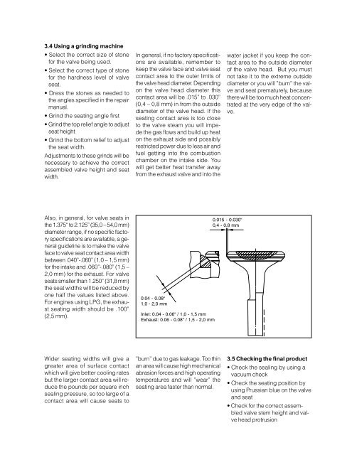
Also, in general, for valve seats in<br />
the 1.375“ to 2.125” (35,0 – 54,0 mm)<br />
diameter range, if no specific factory<br />
specifications are available, a general<br />
guideline is to make the valve<br />
face to valve seat contact area width<br />
between .040”-.060” (1,0 – 1,5 mm)<br />
for the intake and .060”-.080” (1,5 –<br />
2,0 mm) for the exhaust. For valve<br />
seats smaller than 1.250” (31,8 mm)<br />
the seat widths will be reduced by<br />
one half the values listed above.<br />
For engines using LPG, the exhaust<br />
seating width should be .100”<br />
(2,5 mm).<br />
0.04 - 0.08“<br />
1,0 - 2,0 mm<br />
Inlet: 0.04 - 0.06“ / 1,0 - 1,5 mm<br />
Exhaust: 0.06 - 0.08“ / 1,5 - 2,0 mm<br />
0.015 - 0.030“<br />
0,4 - 0,8 mm<br />
Wider seating widths will give a<br />
greater area of surface contact<br />
which will give better cooling rates<br />
but the larger contact area will reduce<br />
the pounds per square inch<br />
sealing pressure, so too large of a<br />
contact area will cause seats to<br />
”burn” due to gas leakage. Too thin<br />
an area will cause high mechanical<br />
abrasion forces and high operating<br />
temperatures and will ”wear” the<br />
seating area faster than normal.<br />
3.5 Checking the final product<br />
• Check the sealing by using a<br />
vacuum check<br />
• Check the seating position by<br />
using Prussian blue on the valve<br />
and seat<br />
• Check for the correct assembled<br />
valve stem height and valve<br />
head protrusion<br />
9