Firestone Air Springs Catalog - MRO Stop
Firestone Air Springs Catalog - MRO Stop
Firestone Air Springs Catalog - MRO Stop

You also want an ePaper? Increase the reach of your titles
YUMPU automatically turns print PDFs into web optimized ePapers that Google loves.
Buy Online at http://www.mrostop.com/products/pneumatics/air-springs/firestone-air-springs.html<br />
AIRSTROKE ACTUATION<br />
SELECTION<br />
1. Refer to the selection guide on page 32 for <strong>Air</strong>stroke force<br />
and stroke capabilities. After your list of possibilities has been<br />
reduced to one or two air springs, then turn to the individual<br />
data page for more detailed information on those parts.<br />
2. STROKE: The maximum STROKE CAPABILITY is the difference<br />
between the height corresponding to the “start of<br />
the shaded area” minus the minimum height. This entire<br />
stroke, or any portion thereof, may be used. If an internal<br />
rubber bumper is required, please note that the minimum<br />
height is increased, and therefore, the total stroke is<br />
decreased.<br />
3. FORCE: Read the forces directly from the static data chart,<br />
or, use the force table located under the chart. Notice that<br />
the force generally decreases as height increases. This feature<br />
is discussed in detail on page 12 in the section entitled<br />
“How to Use the Static Data Chart.”<br />
4. SELECT THE END CLOSURES AND AIR INLET SIZE:<br />
Most <strong>Air</strong>stroke actuators are available with permanently<br />
attached plates or bead ring attachments. If an alternate end<br />
closure option is available, it is so stated under the cross<br />
sectional view of the part. Please refer to page 6 for a<br />
detailed discussion of end closure options.<br />
DOWN AND UP STOPS<br />
Positive stops in both directions (compression and extension)<br />
should always be used with <strong>Air</strong>stroke actuators .<br />
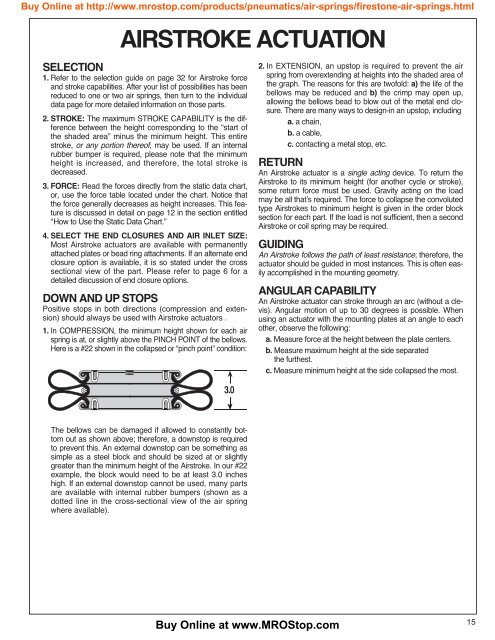
1. In COMPRESSION, the minimum height shown for each air<br />
spring is at, or slightly above the PINCH POINT of the bellows.<br />
Here is a #22 shown in the collapsed or “pinch point” condition:<br />
2. In EXTENSION, an upstop is required to prevent the air<br />
spring from overextending at heights into the shaded area of<br />
the graph. The reasons for this are twofold: a) the life of the<br />
bellows may be reduced and b) the crimp may open up,<br />
allowing the bellows bead to blow out of the metal end closure.<br />
There are many ways to design-in an upstop, including<br />
a. a chain,<br />
b. a cable,<br />
c. contacting a metal stop, etc.<br />
RETURN<br />
An <strong>Air</strong>stroke actuator is a single acting device. To return the<br />
<strong>Air</strong>stroke to its minimum height (for another cycle or stroke),<br />
some return force must be used. Gravity acting on the load<br />
may be all that’s required. The force to collapse the convoluted<br />
type <strong>Air</strong>strokes to minimum height is given in the order block<br />
section for each part. If the load is not sufficient, then a second<br />
<strong>Air</strong>stroke or coil spring may be required.<br />
GUIDING<br />
An <strong>Air</strong>stroke follows the path of least resistance; therefore, the<br />
actuator should be guided in most instances. This is often easily<br />
accomplished in the mounting geometry.<br />
ANGULAR CAPABILITY<br />
An <strong>Air</strong>stroke actuator can stroke through an arc (without a clevis).<br />
Angular motion of up to 30 degrees is possible. When<br />
using an actuator with the mounting plates at an angle to each<br />
other, observe the following:<br />
a. Measure force at the height between the plate centers.<br />
b. Measure maximum height at the side separated<br />
the furthest.<br />
c. Measure minimum height at the side collapsed the most.<br />
3.0<br />
The bellows can be damaged if allowed to constantly bottom<br />
out as shown above; therefore, a downstop is required<br />
to prevent this. An external downstop can be something as<br />
simple as a steel block and should be sized at or slightly<br />
greater than the minimum height of the <strong>Air</strong>stroke. In our #22<br />
example, the block would need to be at least 3.0 inches<br />
high. If an external downstop cannot be used, many parts<br />
are available with internal rubber bumpers (shown as a<br />
dotted line in the cross-sectional view of the air spring<br />
where available).<br />
Buy Online at www.<strong>MRO</strong><strong>Stop</strong>.com<br />
15