Firestone Air Springs Catalog - MRO Stop
Firestone Air Springs Catalog - MRO Stop
Firestone Air Springs Catalog - MRO Stop

You also want an ePaper? Increase the reach of your titles
YUMPU automatically turns print PDFs into web optimized ePapers that Google loves.
Buy Online at http://www.mrostop.com/products/pneumatics/air-springs/firestone-air-springs.html<br />
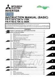
160<br />
Style<br />
160<br />
Two<br />
Ply<br />
Bellows<br />
Description<br />
Blind nuts, 1/4 NPT<br />
Blind nuts, 3/4 NPT<br />
Socket head aluminum bead<br />
rings (bolts, nuts, washers not<br />
included-use 1/4 cap screws)<br />
Order No.<br />
WO1-358-7751<br />
WO1-358-7752<br />
WO1-358-7592<br />
Recommended<br />
Design Position Static<br />
Pressure 0-100 psi<br />
17.5<br />
RECOMMENDED<br />
AIRMOUNT<br />
DESIGNHEIGHT<br />
5.5 INCHES<br />
Do not use <strong>Air</strong>stroke in<br />
shaded area without<br />
consulting <strong>Firestone</strong><br />
Static Data<br />
B9310<br />
35<br />
Assembly weight .........................................................3.0 lbs.<br />
Force to collapse to minimum height (@ 0PSIG) ....140 lbs.<br />
15.0<br />
Volume<br />
100 Psig<br />
120 Psig<br />
30<br />
3/8-16 BLIND NUTS<br />
(5/8 DEEP)<br />
1/4 or 3/4<br />
N PT<br />
AIR INLET<br />
12.5<br />
100 Psig<br />
25<br />
15-20 FT. LBS.<br />
TORQUE<br />
1.75<br />
7.2 MAX O.D.<br />
AT 100 PSIG<br />
VOLUME CU IN. x 10<br />
10.0<br />
7.5<br />
80 Psig<br />
60 Psig<br />
20<br />
15<br />
FORCE LBS x 100<br />
HEIGHT<br />
5.0<br />
40 Psig<br />
10<br />
4.50 DIA.<br />
NOTE: The dotted line on the static data chart shows<br />
the force capabilities of the 160 when attaching an<br />
additional 0.5” pedestal, provided by the customer, to<br />
both ends of the air spring. If an additional pedestal is<br />
not used, the air spring will behave as the solid line<br />
depicts. Without the pedestal the rubber part will contact<br />
the mounting surface at the height of 2.9”. This<br />
could cause wear prematurely to the rubber part.<br />
NOTE: A bead plate part is shown. This part is<br />
also available with bead rings. Bolts are not included.<br />
See pages 8-10 for explanation.<br />
Dynamic Characteristics at 5.5 in. Design Heights<br />
(Required for <strong>Air</strong>mount isolator design only)<br />
Volume @ 100 PSIG = 128 in 3 Natural<br />
Frequency<br />
Gage<br />
Spring<br />
Pressure Load Rate<br />
(PSIG) (lbs.) (lbs./in.) CPM HZ<br />
40 650 327 133 2.22<br />
60 1010 464 127 2.12<br />
80 1390 601 124 2.07<br />
100 1760 737 121 2.02<br />
2.5<br />
0<br />
MAX. HT.<br />
20 Psig<br />
7 6 5 4 3<br />
HEIGHT IN.<br />
See page 12 for instructions on how to use chart.<br />
Force Table (Use for <strong>Air</strong>stroke actuator design)<br />
Volume<br />
Pounds Force<br />
Assembly @ 100<br />
Height PSIG @20 @40 @60 @80 @100<br />
(in.) (in 3 ) PSIG PSIG PSIG PSIG PSIG<br />
6 137 240 560 900 1250 1620<br />
5 118 340 710 1100 1500 1920<br />
4 97 400 810 1240 1670 2110<br />
3 73 440 870 1360 1870 2390<br />
MIN. HT.<br />
2.1”<br />
5<br />
0<br />
Buy Online at www.<strong>MRO</strong><strong>Stop</strong>.com<br />
41