T2100 Excitation Loss Relay
T2100 Excitation Loss Relay
T2100 Excitation Loss Relay

Create successful ePaper yourself
Turn your PDF publications into a flip-book with our unique Google optimized e-Paper software.
50<br />
<strong>T2100</strong> <strong>Excitation</strong> <strong>Loss</strong> <strong>Relay</strong><br />
• Protection of generators against loss<br />
of excitation<br />
• Visual indication of power, pick-up<br />
and relay tripping<br />
• High precision digital countdown<br />
timer for delayed output<br />
• Direct Line-Line supply where neutral<br />
is not available<br />
• Accepts high supply voltage variations:<br />
50 - 110%<br />
• Cost effective and highly reliable<br />
compact design<br />
• 50 hours burn-in before final test<br />
• Operating temperature range:<br />
-20°C to +70°C<br />
• Certified by major marine<br />
classification societies<br />
• Flame retardant enclosure<br />
• DIN rail or screw mounting<br />
φ<br />
Application<br />
The <strong>T2100</strong> <strong>Excitation</strong> <strong>Loss</strong> <strong>Relay</strong> protects<br />
against partial or complete excitation<br />
loss on the synchronous generator.<br />
If a generator under parallel operation<br />
has a low excitation, a high inductive<br />
current is running into the generator.<br />
This current is detected and the faulty<br />
generator breaker is tripped, thus protecting<br />
the generator, and also avoiding<br />
overload on the remaining generators<br />
with a possible blackout of the system.<br />
Together with the T2000 Reverse Power<br />
<strong>Relay</strong>, the T2500 Overcurrent and Short<br />
Circuit <strong>Relay</strong> and the T2700 Power<br />
<strong>Relay</strong>, the <strong>T2100</strong> provides the optimal<br />
solution for complete generator protection,<br />
both in marine and land-based<br />
applications. The <strong>T2100</strong> is type approved<br />
by major marine classification societies.<br />
Function<br />
The <strong>T2100</strong> measures the voltage across<br />
phases L1 and L2 (or between L1 and<br />
neutral for L-N operation) and the<br />
current through a current transducer<br />
attached on phase L1.<br />
The <strong>T2100</strong> calculates I x sin F, representing<br />
the reactive power. If the reactive<br />
power becomes negative and exceeds<br />
the preset level (0.5 - 1.5 x I N<br />
), the pickup<br />
LED will indicate and the delay<br />
timer will be started.<br />
After the preset time (2 - 20 sec.) has<br />
expired, the output relay and LED will<br />
be activated, provided that the negative<br />
reactive power level was exceeded for<br />
the entire delay time.<br />
The output relay is a latching relay. The<br />
latching can be reset or disabled by<br />
bridging terminals 13 and 14.<br />
Installation<br />
Typical setting is 100% current level.<br />
However, it depends on the type of<br />
generator.<br />
Example of setting:<br />
Required trip level: 100%<br />
Generator rating: 714A<br />
Current transformer: 800/5A<br />
Setting: 1 x 714/800 = 0.9 x I N<br />
It is important that the phase where the<br />
current is measured always is connected<br />
to terminals 1 or 2. See connection<br />
diagram.<br />
For L- L operation terminal 3 is<br />
connected to the next phase in the phase<br />
sequence. For L- N operation terminal 3<br />
is connected to neutral.<br />
It is important that the phase sequence<br />
is correct and the current transformer<br />
side nearest the generator side is<br />
connected to terminal 5.<br />
The LED based pick-up indication is<br />
ideal for testing. The <strong>T2100</strong> can be<br />
tested by reducing the excitation on the<br />
generator, until the pick-up LED<br />
indicates exceeding the preset negative<br />
reactive power level.<br />
Troubleshooting<br />
1) If the relay operates on increased<br />
excitation of motor load, the wiring<br />
to terminals 5 and 6 are interchanged.<br />
2) If the relay is not operating in any<br />
power direction and there is voltage<br />
on terminals 1 and 3 or terminals 2<br />
and 3, check that current is floating in<br />
the current circuit terminals 5 and 6.<br />
3) If the relay trips on different levels<br />
when the test is repeated, or operates<br />
in situations with high motor loads,<br />
check that the voltage and current<br />
inputs have the correct phase<br />
relationship and that the phase<br />
sequence is correct.<br />
4) If the relay trips in situations with<br />
high motor loads, check (as in 3) that<br />
the voltage and current inputs have<br />
the correct phase relationship and<br />
that the phase sequence is correct.<br />
10<br />
7.5<br />
Dimensions.<br />
100<br />
Fixing holes<br />
2 x ø 4,5 mm.<br />
115<br />
85<br />
Dimensions in mm.<br />
70
Specifications<br />
<strong>T2100</strong> <strong>Excitation</strong> <strong>Loss</strong> <strong>Relay</strong><br />
L - L SUPPLY<br />
13<br />
RESET<br />
14<br />
7<br />
8<br />
9 5<br />
10 6<br />
C/B TRIP<br />
C/B TRIP<br />
1<br />
2<br />
3<br />
L - N SUPPLY<br />
13<br />
RESET<br />
14<br />
1<br />
2<br />
3<br />
7<br />
8<br />
9<br />
5<br />
10 6<br />
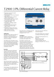
G<br />
L<br />
1<br />
L<br />
2<br />
L<br />
3<br />
LOAD<br />
G<br />
L<br />
1<br />
L<br />
2<br />
L<br />
3<br />
N<br />
LOAD<br />
Connection diagram. <strong>Relay</strong> shown de-energized.<br />
Type Approvals and Certificates<br />
The <strong>T2100</strong> has been designed and tested<br />
for use in harsh environments. The<br />
<strong>T2100</strong> carries the CE label and has been<br />
approved by the following marine<br />
classification societies:<br />
Bureau Veritas<br />
Romanian Register of Shipping<br />
Russian Maritime Register of Shipping<br />
Trip level<br />
Delay<br />
Max. voltage<br />
0.5 - 1.5 x I N<br />
2 - 20 sec.<br />
660V<br />
Voltage range 50 - 110%<br />
Consumption<br />
Continuous current<br />
Frequency range<br />
Output relay<br />
Contact rating<br />
Overall accuracy ±5%<br />
Repeatability ±1%<br />
Operating temperature<br />
Dielectric test<br />
EMC<br />
Approvals<br />
Burn-in<br />
Enclosure material<br />
Weight<br />
Voltage 5VA at U N<br />
Current 0.3VA at I N<br />
2 x I N<br />
45 - 400Hz<br />
Normally de-energized, latching, resetable<br />
AC: 400V, 5A, 1250VA<br />
DC: 150V, 5A, 120W<br />
-20°C to +70°C<br />
2500V, 50Hz<br />
CE according to EN50081-1, EN50082-1, EN50081-2,<br />
EN50082-2<br />
Certified by major marine classification societies<br />
50 hours before final test<br />
Polycarbonate. Flame retardant<br />
0.5kg<br />
Dimensions 70 x 100 x 115mm (H x W x D)<br />
Installation<br />
35mm DIN rail or 4mm (3/16”) screws<br />
The specifications are subject to change without notice.<br />
Type Selection Table<br />
Standard types: I N<br />
= 5A<br />
Terminals<br />
Type 1-3 2-3 I N<br />
Supply Function<br />
<strong>T2100</strong>.0010 230V 5A L-N<br />
<strong>T2100</strong>.0020 480V 415V 5A L-L<br />
<strong>T2100</strong>.0030 450V 400V 5A L-L<br />
<strong>T2100</strong>.0040 110V 100V 1A L-L<br />
<strong>T2100</strong>.0050 110V 100V 5A L-L<br />
<strong>T2100</strong>.0060 110V 100V 5A L-L Current 0.2 - 1.2 x I N<br />
<strong>T2100</strong>.0070 480V 415V 5A L-L Normally energized output,<br />
current 0.05 - 0.15 x I N<br />
<strong>T2100</strong>.0080 110V 100V 5A L-L 24V DC aux. voltage supply,<br />
current 0.2 - 1.2 x I N<br />
Other combinations and voltages are available on request.<br />
Main office:<br />
SELCO A/S<br />
Betonvej 10<br />
DK-4000 Roskilde<br />
Denmark<br />
Phone: + 45 7026 1122<br />
Fax: + 45 7026 2522<br />
e-mail: selco.dk@selco.com<br />
www.selco.com<br />
T2195-51E