T2400 3 Phase Dual Overcurrent Relay
T2400 3 Phase Dual Overcurrent Relay
T2400 3 Phase Dual Overcurrent Relay
- No tags were found...

Create successful ePaper yourself
Turn your PDF publications into a flip-book with our unique Google optimized e-Paper software.
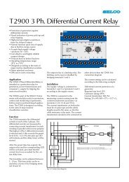
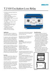
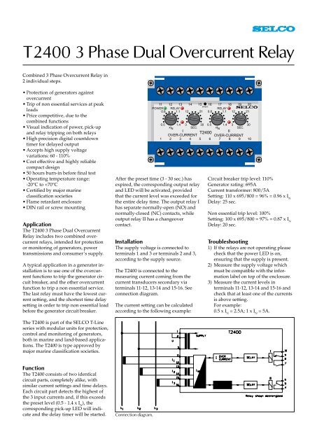
<strong>T2400</strong> 3 <strong>Phase</strong> <strong>Dual</strong> <strong>Overcurrent</strong> <strong>Relay</strong>Combined 3 <strong>Phase</strong> <strong>Overcurrent</strong> <strong>Relay</strong> in2 individual steps.• Protection of generators againstovercurrent• Trip of non essential services at peakloads• Price competitive, due to thecombined functions• Visual indication of power, pick-upand relay tripping on both relays• High precision digital countdowntimer for delayed output• Accepts high supply voltagevariations: 60 - 110%• Cost effective and highly reliablecompact design• 50 hours burn-in before final test• Operating temperature range:-20°C to +70°C• Certified by major marineclassification societies• Flame retardant enclosure• DIN rail or screw mountingApplicationThe <strong>T2400</strong> 3 <strong>Phase</strong> <strong>Dual</strong> <strong>Overcurrent</strong><strong>Relay</strong> includes two combined overcurrentrelays, intended for protectionor monitoring of generators, powertransmissions and consumer’s supply.A typical application in a generator installationis to use one of the overcurrentfunctions to trip the generator circuitbreaker, and the other overcurrentfunction to trip a non essential service.The last relay must have the lowest currentsetting, and the shortest time delaysetting in order to trip non essential loadbefore the generator circuit breaker.The <strong>T2400</strong> is part of the SELCO T-Lineseries with modular units for protection,control and monitoring of generators,both in marine and land-based applications.The <strong>T2400</strong> is type approved bymajor marine classification societies.After the preset time (3 - 30 sec.) hasexpired, the corresponding output relayand LED will be activated, providedthat the current level was exceeded forthe entire delay time. The output relay Ihas separate normally-open (NO) andnormally-closed (NC) contacts, whileoutput relay II has a changeovercontact.InstallationThe supply voltage is connected toterminals 1 and 3 or terminals 2 and 3,according to the supply source.The <strong>T2400</strong> is connected to themeasuring current coming from thecurrent transducers secondary viaterminals 11-12, 13-14 and 15-16. Seeconnection diagram.The current setting can be calculatedaccording to the following example:Circuit breaker trip level: 110%Generator rating: 695ACurrent transformer: 800/5ASetting: 110 x 695/800 = 96% = 0.96 x I NDelay: 25 sec.Non essential trip level: 100%Setting: 100 x 695/800 = 97% = 0.87 x I NDelay: 20 sec.Troubleshooting1) If the relays are not operating pleasecheck that the power LED is on,ensuring that the supply is present.2) Measure the supply voltage whichmust be compatible with the informationlabel on top of the enclosure.3) Measure the current levels interminals 11-12, 13-14 and 15-16 andcheck that at least one of the currentsis above setting.For example:0.5 x I N= 2.5A; 1 x I N= 5A.FunctionThe <strong>T2400</strong> consists of two identicalcircuit parts, completely alike, withsimilar current settings and time delays.Each circuit part detects the highest ofthe 3 input currents and, if this exceedsthe preset level (0.5 - 1.4 x I N), thecorresponding pick-up LED will indicateand the delay timer will be started.Connection diagram.
Specifications<strong>T2400</strong> 3 <strong>Phase</strong> <strong>Dual</strong> <strong>Overcurrent</strong> <strong>Relay</strong>50107.5Dimensions.100Fixing holes2 x ø 4.5 mm85115Dimensions in mm70Type Approvals and CertificatesThe <strong>T2400</strong> has been designed and testedfor use in harsh environments. Theunit is based on standard components,providing long term durability.The <strong>T2400</strong> carries the CE label and hasbeen approved by the following marineclassification societies:Bureau VeritasCroatian Register of ShippingGermanischer LloydRomanian Register of ShippingRussian Maritime Register of ShippingTrip levelsDelaysMax. voltage0.5 - 1.4 x I N3 - 30 sec.660VVoltage range 60 - 110%ConsumptionContinuous currentFrequency rangeOutput relaysContact ratingsOverall accuracy ±5%Repeatability ±1%Operating temperatureDielectric testEMCApprovalsBurn-inEnclosure materialWeightVoltage 5VA at U NCurrent 0.3VA at I N2 x I N45 - 400HzNormally de-energizedAC: 400V, 5A, 2000VADC: 150V, 5A, 150W-20°C to +70°C2500V, 50HzCE according to EN50081-1, EN50082-1, EN50081-2,EN50082-2Certified by major marine classification societies50 hours before final testPolycarbonate. Flame retardant0.5kgDimensions 70 x 100 x 115mm (H x W x D)Installation35mm DIN rail or 4mm (3/16”) screwsThe specifications are subject to change without notice.Type Selection TableStandard types: I N= 5A.TerminalsType 1-3 2-3 I NFunction<strong>T2400</strong>.0010 230V 5A<strong>T2400</strong>.0020 450V 400V 5A<strong>T2400</strong>.0030 110V 100V 5A<strong>T2400</strong>.0040 450V 400V 5A Latching output on relay 1, 6 - 60 sec. delay on relay 1<strong>T2400</strong>.0050 480V 415V 5A<strong>T2400</strong>.0060 450V 400V 1A<strong>T2400</strong>.0070 450V 400V 5A Latching output on relay 1, normally energized relay 1<strong>T2400</strong>.0080 127V 120V 5A<strong>T2400</strong>.0090 24V DC 5ALatching output relays are reset by disconnecting the power supply.Other combinations and voltages are available on request.Main office:SELCO A/SBetonvej 10DK-4000 RoskildeDenmarkPhone: + 45 7026 1122Fax: + 45 7026 2522e-mail: selco.dk@selco.comwww.selco.comT2495-62E