T3200 Insulation Monitoring Relay - Littelfuse
T3200 Insulation Monitoring Relay - Littelfuse
T3200 Insulation Monitoring Relay - Littelfuse

You also want an ePaper? Increase the reach of your titles
YUMPU automatically turns print PDFs into web optimized ePapers that Google loves.
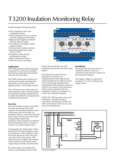
<strong>T3200</strong> <strong>Insulation</strong> <strong>Monitoring</strong> <strong>Relay</strong>Double <strong>Insulation</strong> <strong>Monitoring</strong> <strong>Relay</strong>• Price competitive due to thecombined functions• Visual indication of power, pick-upand relay tripping on both relays• High precision digital countdowntimer for delayed output• Cost effective and highly reliablecompact design• 50 hours burn-in before final test• Operating temperature range:-20°C to +70°C• Certified by major marineclassification societies• Flame retardant enclosure• DIN rail or screw mountingApplicationThe <strong>T3200</strong> <strong>Insulation</strong> <strong>Monitoring</strong> <strong>Relay</strong>is intended for continuous insulationmonitoring on three-phased insulatednetworks on board ships.The <strong>T3200</strong> continuously monitors twosystems, galvanically separated fromeach other, e.g. the busbar and thelighting system, or two busbar systems.The unit features two output relays foralarm purposes and two analog outputsfor instrument reading. Instruments areavailable from SELCO as standard sizedswitchboard instruments.FunctionFor each insulation system (I and II) theelectronic measuring circuit willcompare the measured insulation valueto the preset value of the relay. Aninsulation drop to a value lower than thepreset value will cause activation of thecorresponding output relayresulting in alarm signals to be obtainedbetween terminals 6 and 7 or 9 and 10(system I or system II respectively).Consequently, the output relays will bedeactivated when the insulation valuesare satisfactory, while insulation valueslower than the preset value will causeactivation of the output relays. Thismeans that power supply interruptionswill not result in alarm signals as theoutput relays normally are deactivated.The alarm signal can be delayed bymeans of a presetting function on thefront of the unit. In this way onlycontinuous earth faults will cause alarmsignals.The instrument output has beenadapted for connection of amegaohmmeter which indicates theactual insulation level, either by meansof two instruments simultaneouslyindicating for both insulation systems (Iand II), or by means of one instrumentwhich can be connected to the twoinstrument outputs via a change-overswitch. See connection diagram.NOTE: The <strong>T3200</strong> operates only on ACinstallations. <strong>Insulation</strong> faults inconnection with thyristor controls andother semiconductor devices can causeerrors in measurements.Connection Diagram.123131511SYS. 1SYS. 2<strong>T3200</strong>L1L2L 3InstallationThe measuring circuits for the twoinsulation systems I and II areconnected to the network as shown onthe connection diagram.The supply voltage is connected toterminals 1-3 or 2-3 according to thesupply source.SYS.1SYS.2COM. 18INS. 1 19INS. 2 2056789E232310 + -
Specifications<strong>T3200</strong> <strong>Insulation</strong> <strong>Monitoring</strong> <strong>Relay</strong>50107.5Dimensions.100Fixing holes2 x ø 4.5 mm85115Dimensions in mm70Type Approvals and CertificatesThe <strong>T3200</strong> has been designed and testedfor use in harsh environments. The unitis based on standard components,providing long term durability.The <strong>T3200</strong> carries the CE label and hasbeen approved by the following marineclassification societies:Bureau VeritasPolish Register of ShippingRomanian Register of ShippingRussian Maritime Register of Shipping<strong>Insulation</strong> levelDelayMax. voltage0 - 5MW1 - 10 sec.660VVoltage range 80 - 110%ConsumptionFrequency rangeMeasuring voltageInternal resistanceInstrument outputInstrument resistanceOutput relaysContact ratingsOverall accuracyOperating temperatureDielectric testEMCApprovalsBurn-inEnclosure materialWeightMax. 2VA45 - 65Hz15V DC200kW0 - 1mAMax. 100WNormally de-energizedAC: 400V, 2A, 250VADC: 110V, 2A, 100W±5% of preset value-20°C to +70°C2500V, 50HzCE according to EN50081-1, EN50082-1, EN50081-2,EN50082-2Certified by major marine classification societies50 hours before final testPolycarbonate. Flame retardant0.5kgDimensions 70 x 100 x 115mm (H x W x D)Installation35mm DIN rail or 4mm (3/16”) screwsThe specifications are subject to change without notice.Type Selection TableTerminalsType 1-3 2-3 Function<strong>T3200</strong>.0010 230V<strong>T3200</strong>.0020 450V 400V<strong>T3200</strong>.0030 480V 415V<strong>T3200</strong>.0040 24V DC With 24V DC/DC converter<strong>T3200</strong>.0050 110V 100V<strong>T3200</strong>.0060 127V 120VOther voltages are available on request.AccessoriesDimensions WeightE2323.0010 Megaohmmeter 96x96mm 0.5kgE2324.0010 Kiloohmmeter 96x96mm 0.5kgE2333.0010 Megaohmmeter 144x144mm 0.8kgMain office:SELCO A/SBetonvej 10DK-4000 RoskildeDenmarkPhone: + 45 7026 1122Fax: + 45 7026 2522e-mail: selco.dk@selco.comwww.selco.comT3295-62E