Technical Manual UK.indd - CTC
Technical Manual UK.indd - CTC
Technical Manual UK.indd - CTC

You also want an ePaper? Increase the reach of your titles
YUMPU automatically turns print PDFs into web optimized ePapers that Google loves.
electronic<br />
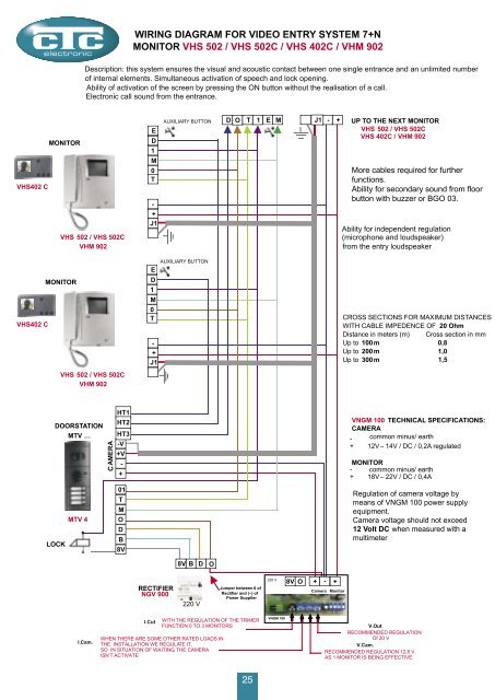
WIRING DIAGRAM FOR VIDEO ENTRY SYSTEM 7+N<br />
MONITOR VHS 502 / VHS 502C / VHS 402C / VHM 902<br />
Description: this system ensures the visual and acoustic contact between one single entrance and an unlimited number<br />
of internal elements. Simultaneous activation of speech and lock opening.<br />
Ability of activation of the screen by pressing the ON button without the realisation of a call.<br />
Electronic call sound from the entrance.<br />
VHS402 C<br />
MONITOR<br />
VHS 502 / VHS 502C<br />
VHM 902<br />
E<br />
D<br />
1<br />
M<br />
0<br />
T<br />
-<br />
+<br />
J1<br />
AUXILIARY BUTTON<br />
D O T 1 E M<br />
J1<br />
-<br />
+<br />
UP TO THE NEXT MONITOR<br />
VHS 502 / VHS 502C<br />
VHS 402C / VHM 902<br />
More cables required for further<br />
functions.<br />
Ability for secondary sound from floor<br />
button with buzzer or BGO 03.<br />
Ability for independent regulation<br />
(microphone and loudspeaker)<br />
from the entry loudspeaker<br />
VHS402 C<br />
MONITOR<br />
VHS 502 / VHS 502C<br />
VHM 902<br />
AUXILIARY BUTTON<br />
E<br />
D<br />
1<br />
M<br />
0<br />
T<br />
-<br />
+<br />
J1<br />
CROSS SECTIONS FOR MAXIMUM DISTANCES<br />
WITH CABLE IMPEDENCE OF 20 Ohm<br />
Distance in meters (m) Cross section in mm<br />
Up to 100m 0,8<br />
Up to 200m 1,0<br />
Up to 300m 1,5<br />
DOORSTATION<br />
MTV …<br />
LOCK<br />
MTV 4<br />
AMERA<br />
C<br />
HT1<br />
HT2<br />
HT3<br />
-V<br />
+V<br />
-<br />
+<br />
01<br />
T<br />
M<br />
O<br />
D<br />
B<br />
8V<br />
VNGM 100 TECHNICAL SPECIFICATIONS:<br />
CAMERA<br />
- common minus/ earth<br />
+ 12V – 14V / DC / 0,2A regulated<br />
MONITOR<br />
- common minus/ earth<br />
+ 18V – 22V / DC / 0,4A<br />
Regulation of camera voltage by<br />
means of VNGM 100 power supply<br />
equipment.<br />
Camera voltage should not exceed<br />
12 Volt DC when measured with a<br />
multimeter<br />
8V B<br />
D<br />
O<br />
RECTIFIER<br />
NGV 900<br />
220 V<br />
Jumper between 0 of<br />
Rectifier and (–) of<br />
Power Supplier<br />
220 V<br />
8V O<br />
- + +<br />
Camera<br />
Monitor<br />
I.Cam.<br />
I.Cut<br />
WITH THE REGULATION OF THE TRIMER<br />
FUNCTION 0 TO 3 MONITORS<br />
WHEN THERE ARE SOME OTHER RATED LOADS IN<br />
THE INSTALLATION WE REGULATE IT,<br />
SO IN SITUATION OF WAITING, THE CAMERA<br />
ISN’T ACTIVATE<br />
25<br />
25<br />
VNGM 100<br />
V.Out<br />
RECOMMENDED REGULATION<br />
Of 20 V<br />
V.Cam.<br />
RECOMMENDED REGULATION 12,8 V<br />
AS 1 MONITOR IS BEING EFFECTIVE