Large-eddy Simulation of Realistic Gas Turbine Combustors
Large-eddy Simulation of Realistic Gas Turbine Combustors
Large-eddy Simulation of Realistic Gas Turbine Combustors

Create successful ePaper yourself
Turn your PDF publications into a flip-book with our unique Google optimized e-Paper software.
300 (a)<br />
200<br />
(b)<br />
Axial Velocity<br />
200<br />
100<br />
0<br />
Swirl Velocity<br />
100<br />
0<br />
-100<br />
-100<br />
-2 -1.5 -1 -0.5 0 0.5 1 1.5 2<br />
-200<br />
-2 -1.5 -1 -0.5 0 0.5 1 1.5 2<br />
Axial Velocity<br />
200<br />
150<br />
100<br />
50<br />
0<br />
-50<br />
(c)<br />
Swirl Velocity<br />
150<br />
100<br />
50<br />
0<br />
-50<br />
-100<br />
(d)<br />
-100<br />
-2 -1.5 -1 -0.5 0 0.5 1 1.5 2<br />
-150<br />
-2 -1.5 -1 -0.5 0 0.5 1 1.5 2<br />
200<br />
(e)<br />
100<br />
(f)<br />
Axial Velocity<br />
100<br />
0<br />
Swirl Velocity<br />
50<br />
0<br />
-50<br />
-100<br />
-2 -1.5 -1 -0.5 0 0.5 1 1.5 2<br />
Normalized Radius<br />
-100<br />
-2 -1.5 -1 -0.5 0 0.5 1 1.5 2<br />
Normalized Radius<br />
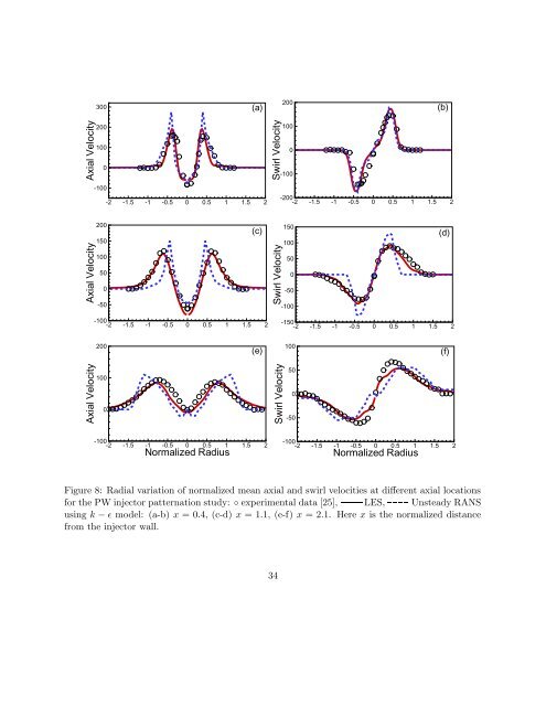
Figure 8: Radial variation <strong>of</strong> normalized mean axial and swirl velocities at different axial locations<br />
for the PW injector patternation study: ◦ experimental data [25], LES, Unsteady RANS<br />
using k − ɛ model: (a-b) x = 0.4, (c-d) x = 1.1, (e-f) x = 2.1. Here x is the normalized distance<br />
from the injector wall.<br />
34