TRP-C31 User's Manual Ethernet To RS232/422 ... - Cru Power Oy
TRP-C31 User's Manual Ethernet To RS232/422 ... - Cru Power Oy
TRP-C31 User's Manual Ethernet To RS232/422 ... - Cru Power Oy

You also want an ePaper? Increase the reach of your titles
YUMPU automatically turns print PDFs into web optimized ePapers that Google loves.
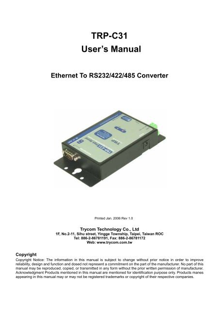
<strong>TRP</strong>-<strong>C31</strong><br />
User’s <strong>Manual</strong><br />
<strong>Ethernet</strong> <strong>To</strong> <strong>RS232</strong>/<strong>422</strong>/485 Converter<br />
Printed Jan. 2006 Rev 1.0<br />
Trycom Technology Co., Ltd<br />
1F, No.2-11, Sihu street, Yingge <strong>To</strong>wnship, Taipei, Taiwan ROC<br />
Tel: 886-2-86781191, Fax: 886-2-86781172<br />
Web: www.trycom.com.tw<br />
Copyright<br />
Copyright Notice: The information in this manual is subject to change without prior notice in order to improve<br />
reliability, design and function and dosed not represent a commitment on the part of the manufacturer. No part of this<br />
manual may be reproduced, copied, or transmitted in any form without the prior written permission of manufacturer.<br />
Acknowledgment Products mentioned in this manual are mentioned for identification purpose only. Products manes<br />
appearing in this manual may or may not be registered trademarks or copyright of their respective companies.
1 Introduction…………………………………………………………………….………….…….…….3<br />
1-1Feature…………..………………………………………………………………….…….…….…….3<br />
1-2 Specification………………………………………………………………………..…….…………3<br />
2 Hardware Descriptions…………………………………………………………….…….…….…… 4<br />
2-1 Panel Layout…………………..……..……………………………………………….……..………4<br />
2-2 Serial Connection……………………………………………………………………………..……5<br />
2-3 <strong>Power</strong> Connection……………………..…………………………………………………………...5<br />
2-4 <strong>Ethernet</strong> Connection……………………..………………………………………………………...5<br />
2-5 Reset Button.......……………………………..…………………………………………………..…5<br />
2-6 Dip Switches.....…………………………………………………………………………………..…5<br />
2-7 DB9 Pin Configurations….…………………………………………………………….……….…6<br />
3 Default Settings……………………………………………………………………………….……....6<br />
4 Install <strong>TRP</strong>-<strong>C31</strong> Hardware………………………………………………………….. …….………...7<br />
4-1 RS485 Wiring……..…………………………………………………………………..……………..7<br />
4-2 RS<strong>422</strong> Wiring…………..……………………………………………………………..……………..7<br />
4-3 <strong>RS232</strong> ………………..………………………………………………………………..……………..7<br />
4-4 RJ-45 Wiring………..………………………………………………………………….………....…8<br />
5 Install “<strong>TRP</strong>-C3X Manager” Utility……………………………………………………..…………..8<br />
6 Updating a <strong>TRP</strong>-<strong>C31</strong> Existing Installation……………………………………………………….10<br />
7 How to configure <strong>TRP</strong>-<strong>C31</strong>….…………………………………………………………….………..11<br />
7-1 Using <strong>TRP</strong>-C3X Manager………………………………………..……………………………….11<br />
7-1-1 Searching LAN for <strong>TRP</strong>-<strong>C31</strong>………………………………………………………………..…11<br />
7-1-2 Configuring Server Properties………………………………………………………………..12<br />
7-2 Using Console Mode………………………………………………………..…………………….18<br />
7-2-1 Console Mode Hardware Wiring…………………………………………………..………….18<br />
7-2-2 Console Mode Software Install……………………………………………..………………...18<br />
7-3 Using Telnet……………………………………………………………………………….……….20<br />
7-4 Using Web Server………………..………………………………………………………………..22<br />
8 Virtual-Com…………………………………………………………………………………………...22<br />
8-1 Installing Virtual COM Port………………………………………………………………………23<br />
8-2 Configuring Virtual COM Port…………………………………………….……………………..24<br />
8-3 Uninstalling the Virtual COM Port……………………………………………………………...27<br />
8-4 Removing the Virtual COM port with Manager Software…..……….………………………27<br />
8-5 Removing the Virtual COM Port using Device Manager……………………………………27<br />
9 Application……………………………………………………………………………………………28<br />
9-1 Direct IP Mode……………………………………………………………………………………..28<br />
9-2 Virtual COM Mode…………….…………………………………………………………………..28<br />
9-3 Paired Mode…..……………………………………………………………………………………29<br />
9-4 Heart Beat…..………………………………………………………………………………………29<br />
10 Using <strong>TRP</strong>COM Utility For Connect <strong>RS232</strong>/<strong>422</strong>/485 Device………………………………..30<br />
11 <strong>RS232</strong>/<strong>422</strong> Loop Test……………………………………………………………………………...31<br />
12 Troubleshooting……………………………………………………………………………….......32<br />
2
1. Introduction<br />
<strong>TRP</strong>-<strong>C31</strong>, a compact, one-port serial device, is designed to instantly convert data from <strong>RS232</strong><br />
/<strong>422</strong>/485 interfaces to a 10/100Mbps <strong>Ethernet</strong> network running at the TCP/IP protocol. By using<br />
a standard COM port and existing network infrastructure the device allow you to link together<br />
serial peripherals that are distant from one another from Windows, Linux and Unix without the<br />
need to install any specific cabling or modify existing software and industry standard DIN rail<br />
design enables fast and professional installation.<br />
The <strong>TRP</strong>-<strong>C31</strong> operates in “Direct IP Mode”, “Virtual COM Mode”, and “Paired Mode”. It has one<br />
synchronous DB-9 serial ports, both equip 10/100 Mbps <strong>Ethernet</strong> RJ-45 connection. The<br />
<strong>Ethernet</strong> port will auto-select 10BaseT or 100BaseTX. <strong>TRP</strong>-<strong>C31</strong> also offers a Heart Beat feature<br />
to ensure a reliable communicating connection.<br />
1-1. Features<br />
‣ Supports RS-232, RS-<strong>422</strong>, and RS-485 serial interface<br />
‣ In Server mode supports individual client sessions for security.<br />
‣ Virtual COM drivers for Windows NT/98/ME/2000/XP<br />
‣ Fully compatible with <strong>Ethernet</strong> and TCP/IP protocol.<br />
‣ Supports 10/100 Mbps <strong>Ethernet</strong><br />
‣ Auto direction flow control on RS-485.<br />
‣ All RS<strong>422</strong>/485 signals provide surge protection and over current protection.<br />
‣ Supported baud rate up to 230.4 Kbps.<br />
‣ <strong>Power</strong>/Link/COM Flow Flow mode LED indicator.<br />
‣ Support intranet and internet system setting function.<br />
‣ Support screw terminal and standard external DC power adaptor.<br />
‣ <strong>Power</strong> input requirement from DC +10V to +15V.<br />
1-2. Specification.<br />
• <strong>Power</strong> Input Voltage: DC +10V to +15V<br />
• Serial Memory: output: 64K bytes per port<br />
• LAN: 10/100 Mbps Auto-detecting – 10/100Base T.<br />
• Serial Interfaces: RS-232 - TX, RX, RTS, CTS, DTR, DSR, DCD, GND<br />
RS-<strong>422</strong> – TX+, TX-, RX+, RX-, RTS+, RTS-, CTS+, CTS-, GND<br />
RS-485 - Data +, Data –, GND<br />
• Data Rate: 110 bps to 230.4 k bps<br />
• Parity: none, even, odd, mark, space<br />
• Data Bits: 5, 6, 7 or 8<br />
• Stop Bits: 1, 1.5 or 2<br />
• Protocol: TCP, IP, ARP, DHCP, Telnet, HTTP, UDP, ICMP<br />
• Din-Rail mountable: Yes.<br />
• <strong>Power</strong> supply: Screw terminal, or standard external DC adapter.<br />
• <strong>Power</strong> consumption: 500 mA.<br />
• Operating Temperature: -20 to 65 °C.<br />
• Storage Temperature: -20 to 65 °C.<br />
• Humidity: 0 – 90% Non-Condensing.<br />
• Approvals: CE, FCC.<br />
• Dimensions: 113(L)*77(W)*26(H) mm.<br />
3
2. Hardware Description<br />
The following information is provided to give the user an understanding of how to connect the<br />
<strong>TRP</strong>-<strong>C31</strong> to the LAN and serial device. A review of the switch settings and the functionality of the<br />
LED’s are also provided.<br />
2-1. Panel layout<br />
4
TX/RX LED: COM. Transiting/Receiving<br />
DC Jack: Input from +10V to +15V.<br />
(Pleas use the 5.5*2.1mm DC JACK).<br />
LINK LED:<br />
<strong>Ethernet</strong> Connection.<br />
PWR LED: System is ready.(Blinking)<br />
2-2. Serial Connection<br />
The <strong>TRP</strong>-<strong>C31</strong> has one DB-9 male connectors. The serial port is configured as a DTE (data<br />
terminal equipment) device. All PC COM ports are DTE ports. A null modem cable is required to<br />
make a connection between the COM port on a PC and the <strong>TRP</strong>-<strong>C31</strong> serial port. straight through<br />
cable is required to connect the <strong>TRP</strong>-<strong>C31</strong> serial port to a DCE device.<br />
2-3. <strong>Power</strong> Connection<br />
The <strong>TRP</strong>-<strong>C31</strong> has a two pins terminal block and power jack. <strong>Power</strong> can apply on either terminal<br />
block or the power jack. It accepts 9-15VDC/500mA power supply. When power is apply a red<br />
light label as run will flash every one second to indicate the system is up and running.<br />
2-4. <strong>Ethernet</strong> Connection<br />
A straight-through <strong>Ethernet</strong> cable can be used to connect the serial server to an <strong>Ethernet</strong> hub,<br />
switch, or wall plate. A crossover <strong>Ethernet</strong> cable can be used to make a connection directly to the<br />
NIC (Network Interface Card) on a PC or laptop.<br />
2-5. Reset Button<br />
The reset button can be found between the switch and terminal block. <strong>To</strong> reset the unit manually<br />
apply power, insert a small plastic tool, and press lightly depressing switch. Hold for 3 seconds<br />
and release. The Link and Run light will go out and turn back on. The <strong>TRP</strong>-<strong>C31</strong> will revert to the<br />
last setting.<br />
2-6. Dip Switches<br />
A double DIP switch allows the <strong>TRP</strong>-<strong>C31</strong> to be placed into Console/Loop back/Default/Data<br />
Mode.<br />
When all these switches are moved into the ON position, the<strong>TRP</strong>-<strong>C31</strong> enters Console Mode,<br />
allowing configuration of the <strong>TRP</strong>-<strong>C31</strong> from a PC running a terminal program such as<br />
Hyper-terminal. When the <strong>TRP</strong>-<strong>C31</strong> enters Console Mode, the Console Mode screen will appear<br />
5
in the Hyper-terminal program window. The serial port settings must be 8-N-1 at 9600 baud.<br />
When the DIP switches are switched to the ON OFF position, the <strong>TRP</strong>-<strong>C31</strong> will work at Loop<br />
back Mode, all data is sent back immediately.<br />
When the DIP switches are switched to the OFF ON position, the <strong>TRP</strong>-<strong>C31</strong> will revert to its<br />
factory version firmware no matter what newer firmware has been upgraded.<br />
When all of the DIP switches are switched back to the OFF position, the <strong>TRP</strong>-<strong>C31</strong> will enter Data<br />
Mode (RS-232, RS-<strong>422</strong> or RS-485).<br />
2-7. DB9 Pin Configuration<br />
Pin RS-232 RS-<strong>422</strong> RS-485<br />
1 DCD RXD (-)<br />
2 RXD RXD (+)<br />
3 TXD TXD (+) D (+)<br />
4 DTR TXD (-) D (-)<br />
5 GND GND GND<br />
6 DSR CTS (-)<br />
7 RTS CTS (+)<br />
8 CTS RTS (+)<br />
9 RI RTS (-)<br />
3. Default Settings<br />
Model Number: <strong>TRP</strong>-<strong>C31</strong><br />
Password: Blank<br />
DHCP: Disable<br />
IP address: 192.168.1.1<br />
Netmask: 255.255.255.0<br />
Gateway : 192.168.1.254<br />
Version & Date: Current firmware version number and date<br />
Serial port: 1<br />
Baud rate: 9600<br />
Data/Stop bits: 8-1<br />
Parity: None<br />
Flow control: None<br />
Protocol: TCP<br />
Serial timeout: 0 seconds<br />
TCP alive timeout: 0 minutes<br />
Connection mode: Server<br />
Delimiter HEX 1: 00<br />
Delimiter HEX 2: 00<br />
6
Force transmit: 0 ms<br />
Serial port mode: <strong>RS232</strong><br />
Maximum connection: 1<br />
Remote IP address: 255.255.255.255<br />
4. Install <strong>TRP</strong>-<strong>C31</strong> Hardware<br />
STEP1: Connect power source with <strong>TRP</strong>-<strong>C31</strong>, if power properly supplies the PWR LED will<br />
blinking.<br />
Warning: User can only choose one of 2 power source, external DC-Jack or Screw<br />
terminal DC input. Do not use external DC-Jack and screw terminal DC input<br />
simultaneously.<br />
STEP2: Connect <strong>TRP</strong>-<strong>C31</strong> with internet port (<strong>Ethernet</strong> Hub or Switch) by RJ45 LAN cable.<br />
If the cable properly connects the “LINK” LED will light up.<br />
STEP3: Connect <strong>TRP</strong>-<strong>C31</strong> with <strong>RS232</strong> or RS<strong>422</strong>/485 serial device.<br />
4-1. RS485 Wiring<br />
The RS-485 mode supports the Transmit and Receive Channels using 2-wire half-duplex<br />
operation. The data lines are differential pair Ground provides a common mode reference.<br />
Refer to the Pin out table for connections.<br />
4-2. RS<strong>422</strong> Wiring<br />
The RS-<strong>422</strong> mode supports 4 channels with full duplex operation for Receive, Transmit, RTS<br />
(Request to send) and CTS (Clear to Send). The data lines are in differential pairs. Ground<br />
provides a common mode reference. <strong>To</strong> use handshaking Flow Control must be set to RTS/CTS<br />
during configuration. Refer to the Pin out table for connections.<br />
7
4-3. <strong>RS232</strong> Wiring<br />
The RS-232 supports 8 channels plus Signal Ground and is configured as DTE like a computer.<br />
Signals are single ended and referenced to Ground. <strong>To</strong> use handshaking, Flow Control must be<br />
set to RTS/CTS during Configuration. Refer to the Pin out table for connections.<br />
4-4. RJ-45 LAN Cable Wiring Diagram<br />
PC <strong>To</strong> <strong>TRP</strong>-<strong>C31</strong>: Please use crossover <strong>Ethernet</strong> cable.<br />
HUB <strong>To</strong> <strong>TRP</strong>-<strong>C31</strong>: Please using straight through cable<br />
5. Install “<strong>TRP</strong>-C3X Manager” Utility<br />
It is recommended the user install the “<strong>TRP</strong>-C3X Manager” utility software and do a search for<br />
all <strong>TRP</strong>-<strong>C31</strong> connected to the LAN. When this is completed a window will list the devices making<br />
them available for configuration.<br />
Configuring the serial server to meet your LAN and application requirement is an easy process<br />
with the available setup menu in the “<strong>TRP</strong>-C3X Manager” software.<br />
8
5-1. How to install <strong>TRP</strong>-C3X manager<br />
The following procedure installs the “<strong>TRP</strong>-C3X Manager” software.<br />
STEP1. Inserting <strong>TRP</strong>-Series CD, in the CD-ROM and select the <strong>TRP</strong>-<strong>C31</strong> Directory.<br />
Run start.exe.<br />
STEP2. The Install Shield Wizard window automatically display and start the setup procedure.<br />
STEP3. Click the “Next” to continue the installation.<br />
STEP4. In the Choose Destination Location window select “Next” to install the “<strong>TRP</strong>-C3X<br />
Manager” software in the default location. (User may select “Browse” to install into<br />
a selected directory)<br />
9
The installation progress will be shown until complete.<br />
STEP5. Click “Finish” when the Install Shield Wizard Complete screen appears. When the<br />
installation is complete user may access to the Manager software in the program files. If loaded in<br />
the default location Go to Start/Programs/Trycom/<strong>TRP</strong>-C3X Manager to open.<br />
6. Updating an Existing Installation<br />
If an older version of the Manager software is already installed, the Modify, repair or remove the<br />
program window will appear when the installation process is initiated. The recommended<br />
procedure is to remove all installed components first. Once the software has been removed,<br />
install the new software.<br />
10
Highlight remove.<br />
7. How to configure <strong>TRP</strong>-<strong>C31</strong><br />
There are 4 ways to access the Server Properties and program the <strong>TRP</strong>-<strong>C31</strong><br />
1. <strong>TRP</strong>-C3X Manager software, see 7-1.<br />
2. Console mode, see 7-2.<br />
3. Telnet, see 7-3.<br />
4. Web Server, see 7-4.<br />
7-1. Using <strong>TRP</strong>-C3X Manager Software<br />
The “<strong>TRP</strong>-C3X Manager” software performs several functions:<br />
A: Searching for <strong>TRP</strong>-<strong>C31</strong> connected to the network<br />
B: Displaying and changing the configuration of <strong>TRP</strong>-<strong>C31</strong><br />
C: Installing virtual COM ports on a computer<br />
D: Displaying and configuring virtual COM ports<br />
E: Uninstalling virtual COM ports on a computer<br />
F: Upgrading the <strong>TRP</strong>-<strong>C31</strong> firmware<br />
G: Monitoring Port Status<br />
H: Saving and Loading Configuration Files<br />
7-1-1.Searching LAN for <strong>TRP</strong>-<strong>C31</strong><br />
Once <strong>TRP</strong>-<strong>C31</strong> is connected to the LAN the <strong>TRP</strong>-C3X Manager software will search it and<br />
display it in a window by name and IP address.<br />
A. Select “<strong>TRP</strong>-C3X Manager” Utility in the program file menu. If the default location was<br />
11
selected during the installation the program will be found under “Start/Programs/Trycom<br />
/<strong>TRP</strong>-C3X” utility. As soon as the “<strong>TRP</strong>-C3X Manager” Utility opens it will initiate<br />
Searching Server and after a few seconds the Serial Server List will display all<br />
(<strong>TRP</strong>-<strong>C31</strong>/32/34) serial servers on the network.<br />
B. <strong>To</strong> manually initiate a search for servers, on the menu side bar select Searching Server<br />
button. The Search Setup box will appear.<br />
It provides two options for searching for servers on the network:<br />
• Specify the IP address of the Serial Server.<br />
• Search all reachable servers<br />
Enter the IP Address assigned to the desired Serial Server or click Search all<br />
reachable servers, click “OK”. The Searching window is shown until all active Serial<br />
Servers on the LAN are listed in the Serial Server List window.<br />
7-1-2.Configuring Server Properties<br />
12
Highlight the serial server in the Serial Server List window and double click to open the<br />
Server Properties window. The Server Properties window is used to configure and store the<br />
Server configuration settings. Details for setting Properties are described in the next chapter.<br />
After configuring as needed, click Update to store the configuration in the server and click<br />
“Yes” to restart the server to make sure all settings are changed to conform to the desired<br />
application.<br />
Server Name<br />
The server name is user configurable. It is recommended users with more than one <strong>TRP</strong>-<strong>C31</strong><br />
connected to the LAN assign a new name to each. When the Manager software searches for<br />
servers on the LAN it will display the server name allowing the user to distinguish between<br />
<strong>TRP</strong>-<strong>C31</strong>s.<br />
Serial Number<br />
Each <strong>TRP</strong>-<strong>C31</strong> has a unique serial number. This is fixed and cannot be changed.<br />
Password<br />
Entering a password activates a security feature on the serial server. Once a password is<br />
entered it will be required to access the menu and make changes.<br />
DHCP<br />
DHCP servers are a part of numerous LAN management systems. The DHCP field has two<br />
selections, “Enable” or “Disable”. Arrow to the desired selection and select enter.<br />
When enabled, <strong>TRP</strong>-<strong>C31</strong> will send a DHCP request to the DHCP server, which will assign a<br />
dynamic IP address, netmask, and gateway to the <strong>TRP</strong>-<strong>C31</strong>. If a DHCP server is not available on<br />
the network the <strong>TRP</strong>-<strong>C31</strong> will time out after 10 seconds and the default values will remain. When<br />
13
DHCP is enabled, the IP address, Netmask and Gateway fields become inaccessible and cannot<br />
be changed by the user.<br />
IP Address<br />
A static IP address can also be assigned in this section of the menu. A dynamic address<br />
assigned by the DHCP server may change if the <strong>TRP</strong>-<strong>C31</strong> looses the <strong>Ethernet</strong> connection or<br />
power is removed. The host (client) communication software requests a connection to the<br />
specific IP address of the serial server. If the DHCP reassigns a different IP address the software<br />
will not be able to communicate with the hardware. It is recommended to use a static IP address.<br />
A static IP address is permanent and will not change unless changed in the menu. In most cases<br />
the network administrator establishes the static address to be used.<br />
Netmask<br />
The default LAN netmask is configured for a Class C address. This maybe reconfigured by the<br />
user.<br />
Gateway<br />
The gateway IP address allows users to access the serial server from outside the LAN.<br />
MAC Address<br />
The MAC address is not adjustable. This is assigned in the factory. Every <strong>Ethernet</strong> device<br />
manufactured has it own unique MAC address.<br />
Version & Date<br />
The currently loaded version of the firmware, and when it was released, are shown here.<br />
Link Status<br />
Link status automatically displays the type of <strong>Ethernet</strong> connection. It will either display 10 BaseT<br />
or 100BaseTX in full duplex or half duplex. This will depend on the LAN, switches, hubs used in<br />
the LAN topology.<br />
Server Serial Port<br />
This field indicates the number of the port for with serial server properties are currently being<br />
displayed. Changing the number in this field will cause all the other fields to display the<br />
properties for the specified port. Note, however, that before changing ports, any change to<br />
properties must be updated (Saved) or the serial server will not retain them.<br />
Baud Rate<br />
The serial port baud rate on the <strong>TRP</strong>-<strong>C31</strong> must match the serial baud rate of the connected<br />
device unless using Virtual COM mode. In Virtual COM mode the software program will establish<br />
serial settings.<br />
14
Data/Parity/Stop<br />
This setting will have to match the data format of the connected device unless using Virtual COM<br />
mode. In Virtual COM mode the software program will establish serial settings.<br />
Flow Control<br />
The flow control setting must match the connected serial device unless using Virtual COM mode.<br />
In Virtual COM mode the software program will establish serial settings.<br />
Protocol<br />
Select TCP or UDP protocol. If the application does not require a UDP connection, select TCP.<br />
TCP guarantees reliable communication with error checking whereas UDP provides faster<br />
transmission.<br />
When UDP mode is chosen the Serial timeout, TCP alive timeout, Connection mode, Connection<br />
at, Maximum connection and Remote IP address fields are replaced with the following three<br />
fields: Destination IP address range, Port number and Source IP address range. In this mode the<br />
server can be configured to broadcast data to and receive data from multiple IP addresses. Four<br />
IP address range fields are provided.<br />
Serial Timeout<br />
Default is 0, or no timeout. Setting timeout to any value between 1 and 65535 seconds activates<br />
it. If communications are idle for specified timeout value the serial server will reset and make<br />
itself available for another connection.<br />
TCP Alive Timeout<br />
This monitors TCP activity. If TCP activity stops for the length of time specified in this field the<br />
connection will be closed. This field can be set to any value between 0 and 255 minutes. If zero,<br />
or no value, is entered into this field the server will not disconnect.<br />
15
Connection Mode<br />
The Connection mode field has three options, Server, Client and Client (no heartbeat). When<br />
Client or Client (no heartbeat) is selected, the Connection at field automatically becomes active<br />
(allowing the user to select <strong>Power</strong> up or Data arrival).<br />
• When using the Virtual COM Port feature, select Server.<br />
• When using a TCP or UDP Socket program, select Server.<br />
• When using Paired Mode communication between two serial servers set up one as a Client<br />
and the other as a Server.<br />
• When connecting to a server that does not support Heartbeat, select Client (no heartbeat).<br />
Delimiter HEX1 and Delimiter HEX 2<br />
These two fields allow the user to enter two ASCII characters (in hex format) that delimit the<br />
beginning and end of a message. When a message with both these delimiters is received at the<br />
serial port, the data contained in the serial buffer is placed in an <strong>Ethernet</strong> packet and sent out the<br />
<strong>Ethernet</strong> port. If only Delimiter 1 is set (Delimiter 2 is zero or blank), upon receiving Delimiter 1<br />
the <strong>TRP</strong>-<strong>C31</strong> will put all the data in the serial buffer in an <strong>Ethernet</strong> packet and send it out the<br />
<strong>Ethernet</strong> port. If serial data greater than 1 kilobyte is received it will automatically be placed in an<br />
<strong>Ethernet</strong> packet and sent out the <strong>Ethernet</strong> port.<br />
Force Transmit<br />
This field allows the user to set a maximum time limit between transmissions of data. The value<br />
set in this field multiplied by 100 ms determines the Force Transmit time. When the elapsed time<br />
reaches the time configured in this field, the TCP/IP protocol will pack the data currently in the<br />
serial buffer into a packet and send it out the <strong>Ethernet</strong> port.<br />
Port Status<br />
This field indicates whether a serial port is connected to a server or by a client.<br />
TCP/UDP Port<br />
The TCP/UDP Port defines a communication port number. In all modes of operating, Virtual<br />
COM, Direct IP, and Paired modes, both the TCP/UDP Client and server port settings must<br />
match.<br />
For example the Virtual COM defaults setting TCP/UDP Port # 4000. If the port # of the <strong>TRP</strong>-<strong>C31</strong><br />
is changed to 4001, the Virtual COM TCP/UDP Port will have to be changed to 4001.<br />
Serial Port Mode<br />
This allows configuration of the serial server for the following modes of operation:<br />
• Console – When this mode is selected and the server is updated, a PC running a<br />
communication program such as Hyper-terminal can communicate with the<br />
serial server via the Console Mode serial port (Port 1 on <strong>TRP</strong>-<strong>C31</strong>), displaying<br />
16
the Server Properties screen and allowing configuration of the server and its<br />
ports.<br />
• Upgrade – When this mode is selected and the server is updated, firmware can be uploaded<br />
into the serial server via the Console Mode serial port or a virtual COM port<br />
appeared to the number of the Console Mode serial port.<br />
• Default – When this mode is selected and the server is updated, it will revert the server to<br />
its default configuration.<br />
• RS-232 – When this mode is selected and the server is updated, the selected serial port<br />
will become a RS-232 serial port on the server.<br />
• RS-<strong>422</strong> – When this mode is selected and the server is updated, the selected serial port<br />
will become a RS-<strong>422</strong> serial port on the server.<br />
• RS-485 – When this mode is selected and the server is updated, the selected serial port will<br />
become a RS-485 serial port on the server.<br />
Connection At<br />
When the Connection Mode field is set to Client or Client (no heartbeat), this field becomes<br />
active, allowing the <strong>TRP</strong>-<strong>C31</strong> (acting as a client) to connect to the server either on <strong>Power</strong> up or<br />
on Data Arrival (first character arriving).<br />
Maximum Connection<br />
This field allows the user to configure the Serial Server to have up to eight TCP connections.<br />
Remote IP Address<br />
This is a security feature that is activated when the IP address of the desired client is<br />
programmed into the remote IP Address setting of the menu. This tells the <strong>TRP</strong>-<strong>C31</strong> to<br />
communicate with only the listed IP address and to filter out all other requests for connection.<br />
The <strong>TRP</strong>-<strong>C31</strong> is setup in the menu as a TCP or UDP server to us this feature.<br />
The default setting is 255.255.255.255. It is recommended not to change this setting until the<br />
application has been tested and is communicating properly. At that point the address filtering<br />
feature of the <strong>TRP</strong>-<strong>C31</strong> can be activated.<br />
Update/Save<br />
Server properties must be updated separately for each serial port. Updating varies slightly<br />
depending on which of the four configuration user interfaces are used.<br />
17
Updating the Server Properties in Manager Software<br />
From the Server Properties screen, click the Update button to store the configuration settings for<br />
the currently selected port. The “vcomui” dialogue box will appear indicating you must restart<br />
the device before the new settings will take effect. Click Yes.<br />
7-2 Using Console Mode<br />
The console mode allows access to the <strong>TRP</strong>-<strong>C31</strong> setup menu. This is one way to reconfigure the<br />
default settings for the application. A serial connection is made between a COM port on the PC<br />
and the <strong>TRP</strong>-<strong>C31</strong> serial port A with a null modem cable. In console mode, the serial port defaults<br />
to an RS-232 interface.<br />
The <strong>TRP</strong>-<strong>C31</strong> serial port default settings are, baud rate 9600, 8 data bits, no parity, and 1 stop bit.<br />
Hyper Terminal should be used for this type of setup. Hyper Terminal’s serial settings are<br />
configured the same as the mentioned default settings of the <strong>TRP</strong>-<strong>C31</strong> and must be set to<br />
VT100 emulation mode. The default settings are used only if they have not been changed<br />
7-2-1 Console Mode Hardware Wiring<br />
7-2-2 Console Mode Software Install<br />
STEP1. Select “Hyper Terminal” WINDOWS Utility<br />
Start ---Accessories---Communications --- Hyper Terminal<br />
18
STEP2.Select “New Connection” and Enter a name, click “OK”<br />
.<br />
STEP3. Enter the COM Port number that <strong>TRP</strong>-<strong>C31</strong> connect using, click “OK”<br />
STEP4. Press the “Space bar” the <strong>TRP</strong>-<strong>C31</strong> firmware setting screen will show.<br />
19
You can set the <strong>TRP</strong>-<strong>C31</strong> by Console mode.<br />
7-3.Using Telnet<br />
Telnet can be used to configure the <strong>TRP</strong>-<strong>C31</strong> Serial Server from any PC on the LAN. The Telnet<br />
window displays the same configuration information shown in Console Mode and allows server<br />
properties to be configured. See chapter 6 for details on Server Properties.<br />
Ensure the PC and <strong>TRP</strong>-<strong>C31</strong> are connected to the LAN, and the serial server is in RS-232,<br />
RS-<strong>422</strong> or RS-485 mode before you can telnet to it and access the configuration screens. From<br />
the Desktop, click Start, and then run. The Run dialogue box will open. Type in Telnet and the IP<br />
address of the Serial Server which to be configured, click OK.<br />
STEP1. Select Start then Click “RUN” then key in the “Telnet IP”<br />
20
STEP2. Click the “OK” <strong>TRP</strong>-<strong>C31</strong> firmware setting will show as following screen. You can set<br />
the <strong>TRP</strong>-<strong>C31</strong> by Telnet mode.<br />
21
7-4 Using the WEB Server mode<br />
The Web Server can be used to configure the <strong>TRP</strong>-<strong>C31</strong> Serial Server from any web browser<br />
software (such as Internet Explorer). Server properties can be set up using three browser pages.<br />
See chapter 6 for details on Server Properties.<br />
In Internet Explorer type the IP Address of the Serial Server into the address field near the top of<br />
the window and press the Enter key. The following window will appear:<br />
8 Virtual-Com<br />
The Virtual COM Port feature allows Windows platform software using standard API calls to<br />
be used in an <strong>Ethernet</strong> application.<br />
Running the Install Virtual COM port software adds a COM Port in the Device Manager of the<br />
operating system. The COM port will look like a standard COM port to Windows software<br />
22
used in most applications allowing the software to open a connection with the serial port<br />
located anywhere on the LAN. When using the virtual COM port the <strong>TRP</strong>-<strong>C31</strong> is configured<br />
as a TCP or UDP Server.<br />
8-1 Installing Virtual COM Port<br />
STEP1. On the Desk <strong>To</strong>p select Start/Programs/Trycom /Install Virtual COM.<br />
STEP2. Select the Search all reachable servers check box, then click OK.<br />
STEP3. The Install Virtual COM program will automatically search the LAN for all available<br />
<strong>TRP</strong>-<strong>C31</strong> serial servers and display them in the Found Server window. Highlight the desired<br />
serial server and click Install. The COMInst window appears.<br />
STEP4. When the COMInst window opens select COM port # to map the serial server to. The<br />
Flow Control, Protocol, IP Address, and Port Number will mirror the settings of the selected<br />
serial server. Highlight the desired COM port # and select OK.<br />
23
Note1. If any settings are changed in this part of the Virtual COM setup it will only affect<br />
the settings in the operating system Device Manager. It will not change the settings in the<br />
<strong>TRP</strong>-<strong>C31</strong>.<br />
Note2. The settings of the Virtual COM port in the Device Manager and the <strong>TRP</strong>-<strong>C31</strong><br />
Configuration menu must match. If the settings do not match, the software connecting to<br />
the Virtual COM port will be unsuccessful in opening the COM port.<br />
Note3. In Windows XP a Hardware Installation window stating that the drivers have not<br />
been tested by Microsoft may appear. Select “Continue Anyway” to proceed with the<br />
installation.<br />
STEP5. When Virtual Com installation completed, click close on the Found Server window to<br />
close Found Server window. <strong>To</strong> confirm installation, go to the Device Manager and select Ports<br />
(COM & LPT). The installed Virtual COM port will be displayed as <strong>TRP</strong>-<strong>C31</strong> COM#.<br />
8-2 Configuring Virtual COM Port<br />
The Virtual COM port can be configured in the Device Manager of the operating system or<br />
the Manager software. In either case the IP Address, Port #, Protocol, and Flow Control<br />
settings must match the <strong>TRP</strong>-<strong>C31</strong> settings for the software to open the Virtual COM port.<br />
STEP1. At the Desk <strong>To</strong>p select Start/Program/Trycom/<strong>TRP</strong>-C3X Manager. Double click the<br />
Virtual COM Configuration button.<br />
STEP2. Double click the COM # displayed in the screen to open the configuration window.<br />
24
STEP3. Make the adjustments and select OK to complete the changes.<br />
8-2-1 Configuration with Device Manager<br />
STEP1. On the Desk <strong>To</strong>p select Start/Settings/Control Panel. Select the System Icon when the<br />
Control Panel window opens.<br />
STEP2. In the System Properties window select the Device Manager Button.<br />
STEP3. In the Device Manager select the + button next to Ports (COM & LPT) to expand and see<br />
the <strong>TRP</strong>-<strong>C31</strong> (COM #). Double click <strong>TRP</strong>-<strong>C31</strong> (COM #) to open the Properties window.<br />
25
STEP4. Select the Configuration tab. From here the same settings found in the <strong>TRP</strong>-<strong>C31</strong><br />
Manager can be adjusted.<br />
26
8-3 Uninstalling the Virtual COM Port<br />
The <strong>TRP</strong>-C3X Manager software Uninstall Virtual Com port feature will remove the mapped<br />
COM port in the Device Manager of Windows 2000 and XP operating systems. It may also be<br />
removed in the Device Manager of Windows 98, ME, NT, 2000, and XP. Windows 98 users will<br />
also find a Remove Virtual COM feature in the programs file.<br />
8-4 Removing the Virtual COM port with Manager Software<br />
STEP1 At the Desk <strong>To</strong>p select Start/Programs/Trycom/<strong>TRP</strong>-C3X Manager.<br />
STEP2.In the Manager window select Virtual COM Configuration. Highlight the mapped COM<br />
port number to be removed.<br />
STEP3 Select Uninstall Virtual COM button. The Manager will ask for confirmation. Select “Yes”<br />
to complete the uninstall procedure.<br />
8-5 Removing the Virtual COM Port using Device Manager<br />
The screen shots were taken from a Windows XP operating system<br />
27
STEP1. On the Desktop select Start/Settings/Control Panel. Select the System icon when the<br />
Manager window opens.<br />
STEP2. Select Device Manager in the Systems Properties window. In the Device Manger<br />
window select the + next to Ports (COM & LPT) to expand.<br />
STEP3. Highlight <strong>TRP</strong>-<strong>C31</strong> (COM #) to be removed, go the Action tab at the top of window<br />
and select uninstall. A confirm Device Removal window will appear. Select OK to<br />
proceed.<br />
STEP4. The <strong>TRP</strong>-<strong>C31</strong> COM # will be removed and the Device Manager window will refresh<br />
and display the remaining COM ports.<br />
Once all the changes have been made move to the Configuration screen, select Save and<br />
press Enter. The restart message will appear. Select “Yes” to save changes. This is necessary to<br />
write the settings to the server.<br />
9. Application<br />
The <strong>TRP</strong>-<strong>C31</strong> allows serial devices to communicate over a LAN or Intranet network. Serial<br />
devices are no longer limited to a physical connection to the PC COM port. They can be installed<br />
anywhere on the LAN using TCP/IP or UDP/IP communications. This will also allow traditional<br />
PC COM ports access to a serial device anywhere on the LAN network.<br />
9-1 Direct IP Mode<br />
Direct IP connections allow applications using TCP/IP or UDP/IP network socket programs to<br />
communicate with the asynchronous serial port on the <strong>TRP</strong>-<strong>C31</strong>. In this type of application the<br />
<strong>TRP</strong>-<strong>C31</strong> is configured to TCP or UDP server. The socket program running on the PC<br />
establishes a communication connection with the <strong>TRP</strong>-<strong>C31</strong>. The raw data is sent directly to and<br />
from the serial port.<br />
9-1 Virtual COM Mode<br />
The Virtual COM mode requires the installation of a driver. When installed a new COM port is<br />
added to the Device Manager. Windows programs using standard Windows API calls will be able<br />
to interface with Virtual ports. The PC will act as the host connecting to the <strong>TRP</strong>-<strong>C31</strong> when the<br />
program opens the virtual COM port.<br />
28
Once the connection is made, the LAN is transparent to the serial device. Applications work just<br />
as if the serial device is connected a host’s physical COM port. The virtual COM port converts the<br />
application’s data into IP packet destined for the <strong>TRP</strong>-<strong>C31</strong>, which in turn converts the IP packet<br />
back to serial data.<br />
In this mode, the<strong>TRP</strong>-<strong>C31</strong> must be set to either TCP/server or UDP/server in the menu with a<br />
designated communication port number. The virtual COM driver is a TCP or UDP client.<br />
9-3 Paired Mode<br />
Paired mode is also called serial tunneling. When this type of configuration is selected additional<br />
software will not have to be loaded on a host PC. In fact a PC is not required to make the<br />
connection. Any two dumb serial devices that can communicate with each other through a serial<br />
link will be able to communicate using two <strong>TRP</strong>-<strong>C31</strong> and the LAN.<br />
Two <strong>TRP</strong>-<strong>C31</strong> are configured with one setup as a TCP or UDP client and the other to TCP/UDP<br />
server. When setting up the Server, the Remote IP address section must contain the address of<br />
the Client. This will allow the Client’s IP address to pass the IP address-filtering feature of the<br />
Server. Conversely, the Remote IP address of the Client must contain the Server’s IP address.<br />
9-4 Heart Beat<br />
The <strong>TRP</strong>-<strong>C31</strong> provides a convenient way to establish reliable communications between two<br />
devices. Communication port 5300 is reserved for the Heartbeat Protocol. Without this feature a<br />
device that loses a connection and stops communicating would not be able to reconnect without<br />
personally attending to the problem. A TCP data connection can be lost when there is a power<br />
failure or temporary loss of an <strong>Ethernet</strong> connection on either the client or server.<br />
If a loss occurs the Heart Beat feature will try to reconnect the TCP data connection every 5<br />
seconds until communications is established again. The Heart Beat feature is available to use<br />
with the Virtual COM Mode, Paired Mode and Direct IP Mode. This is not available when using a<br />
UDP application.<br />
29
10. Using <strong>TRP</strong>COM Utility For Connect <strong>RS232</strong>/<strong>422</strong>/485 Device<br />
<strong>TRP</strong>-Serial Test Utility is demo utility which may help to test direct IP Mode .User may find the<br />
utility in the <strong>TRP</strong>-<strong>C31</strong> support disk. Double click “Trycom Utility”, the installShield Wizard will<br />
guide you complete installation.<br />
User can directly link <strong>TRP</strong>-<strong>C31</strong> to Trycom Remote IO Modules by RS485, The basic wiring<br />
connect.<br />
30
11.<strong>RS232</strong>/<strong>422</strong> Loop Test<br />
STEP1. Adjust the <strong>TRP</strong>-<strong>C31</strong>’s Switch to the “ON, OFF”<br />
STEP2. Run the “Install Virtual-Com” and setting the Virtual-COM.<br />
STEP3. Run the Demo Utility, click the “Settings” then setup the com port status and click the<br />
“Action”!<br />
31
* User may find the DEMO utility in the <strong>TRP</strong>-<strong>C31</strong> disk. Double click “DEMO.EXE”<br />
12 Troubleshooting<br />
Q: Why sometimes Hyperterminal loses characters or display funny characters<br />
A: This happens when you open a new Hyperterminal connection and keep inputting the same<br />
character. The reason is before Hyperterminal receiving two different characters from the other<br />
end, its status is Auto detects, and your port settings haven’t fully take effect, so the transferred<br />
data is not predicable. <strong>To</strong> solve this problem, input two different characters from the other end,<br />
then the Hyperterminal status will show your port settings such as 9600 8-N-1, save this<br />
Hyperterminal connection. Next you open your saved Hyperterminal connection, everything will<br />
be fine.<br />
Q: What should I do when I forget the IP address or baud rate setting of a <strong>TRP</strong>-<strong>C31</strong><br />
A: You can use the searching capability to get the information of all <strong>TRP</strong>-<strong>C31</strong> on the network.<br />
Double clicks on the searched result will show the detail configuration parameters of the device.<br />
Q: Why I cannot open virtual COMx<br />
A: The server settings and virtual COMx settings may not match, please make sure their IP<br />
address, protocol, port and flow control mode are the same, and the remote IP address should<br />
be the host IP address. Besides the <strong>TRP</strong>-<strong>C31</strong> cannot be at Console mode.<br />
Q: Why the arrow keys of hyperterminal in Windows 2000 do not work in Console mode and<br />
telnet<br />
A: Please download new version of hyperterminal. The hyperterminal comes with Windows<br />
2000 does not send the arrow key code properly.<br />
32
Q: Why I am unable to change the parameters of port 1<br />
A: Serial port 1 is designated console port. The default setting for the console port is 9600 8-N-1.<br />
If the serial port 1 is set to console port. It will use the default value that is why it does response<br />
to the change. Please check hardware switch or server properties page to see if the serial port<br />
mode of the port1 is set to console. Please change it to other mode then its parameter can be<br />
changed.<br />
Q: Why the parameters in the web console are different than those in the server properties of<br />
management utility<br />
A: The edited parameters in the web console only take effect after reset <strong>TRP</strong>-<strong>C31</strong>. Web console<br />
show the edited configuration while in the management utility show the running configuration.<br />
That is why they might appear differently it is not recommended to edit server's configuration<br />
using two different tools at the same time. Because all change could be over-written by other<br />
method.<br />
33