485CSP2 - Datasheet - RS-232 to RS-485 Converter
485CSP2 - Datasheet - RS-232 to RS-485 Converter
485CSP2 - Datasheet - RS-232 to RS-485 Converter
- No tags were found...

You also want an ePaper? Increase the reach of your titles
YUMPU automatically turns print PDFs into web optimized ePapers that Google loves.
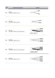
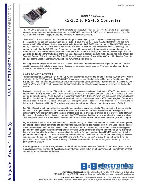
Integrate – Expand – Simplify B&B ELECTRONICS PRODUCT INFORMATIONModel <strong><strong>485</strong>CSP2</strong><strong>RS</strong>-<strong>232</strong> <strong>to</strong> <strong>RS</strong>-<strong>485</strong> <strong>Converter</strong><strong><strong>485</strong>CSP2</strong>-0406-1/3The <strong><strong>485</strong>CSP2</strong> converts unbalanced <strong>RS</strong>-<strong>232</strong> signals <strong>to</strong> balanced, full or half-duplex <strong>RS</strong>-<strong>485</strong> signals. It also providestransient surge protection and fast acting fuses on the <strong>RS</strong>-<strong>485</strong> data lines. <strong>RS</strong>-<strong>485</strong> is an enhanced version of the <strong>RS</strong>-422 Standard. It allows multiple drivers and receivers on a two-wire system.The <strong>RS</strong>-<strong>232</strong> port has a female DB-25 connec<strong>to</strong>r with pins 2 (TD), 3 (RD), and 7 (Signal Ground) supported. Pins 4(RTS) and 5 (CTS) are tied <strong>to</strong>gether, and pins 6 (DSR), 8 (CD), and 20 (DTR) are also tied <strong>to</strong>gether. Pins 1 (FrameGround) and 7 (Signal Ground) are connected straight through <strong>to</strong> the <strong>RS</strong>-<strong>485</strong> terminal blocks. The <strong><strong>485</strong>CSP2</strong> has twoLEDs, a Transmit Enable LED <strong>to</strong> show when the <strong>RS</strong>-<strong>485</strong> driver is enabled, and a Receive Data LED showing dataappearing at pin 3 of the <strong>RS</strong>-<strong>232</strong> port. These are very useful for determining if data is getting through the converter.Note that the Transmit Enable LED indicates only that the <strong>485</strong> driver is enabled, data must be present on pin 2 of the<strong>232</strong> side for data <strong>to</strong> be transmitted out of the <strong>485</strong> side. If no data is present, no data will be transmitted even though theTransmit Enable LED is illuminated. The <strong>RS</strong>-<strong>485</strong> terminal blocks support Transmit Data (A) and (B), Receive Data (A)and (B), Frame Ground, Signal Ground, and +12 VDC input. See Figure 1.For the protection properties on the <strong><strong>485</strong>CSP2</strong> <strong>to</strong> work, the Frame Ground terminal block or pin 1 on the <strong>RS</strong>-<strong>232</strong> sidemust be connected directly <strong>to</strong> a good frame (chassis, green wire, or earth) ground. This must be a low impedanceconnection for the <strong><strong>485</strong>CSP2</strong> <strong>to</strong> be effective.Jumper ConfigurationThe jumper labeled “CONTROL” on the <strong><strong>485</strong>CSP2</strong> sets the method in which the tristate of the <strong>RS</strong>-422/<strong>485</strong> driver will becontrolled. In the “RTS” position, the <strong>RS</strong>-422/<strong>485</strong> driver must be controlled directly by Request <strong>to</strong> Send (pin 4) of the<strong>RS</strong>-<strong>232</strong> side. Your software must be written <strong>to</strong> raise this output handshake line when transmitting out <strong>to</strong> the <strong>RS</strong>-422/<strong>485</strong>system. When you are through transmitting, the handshake line must be lowered <strong>to</strong> allow other drivers on the line <strong>to</strong>transmit.Putting the control jumper in the “SD” position enables an au<strong>to</strong>matic send data circuit in the <strong><strong>485</strong>CSP2</strong> that takes care ofthe control of the <strong>RS</strong>-422/<strong>485</strong> driver. The circuit senses the data on Transmit Data (pin 2) of the <strong>RS</strong>-<strong>232</strong> side and turnson the <strong>RS</strong>-422/<strong>485</strong> driver. When the data is through transmitting, the <strong><strong>485</strong>CSP2</strong> waits one millisecond before shutting offthe <strong>RS</strong>-422/<strong>485</strong> driver. This preset timeout allows continuous transmission of data at 9600 baud or higher. If other baudrates are desired, this timeout can be changed by changing the value of capaci<strong>to</strong>r C6 and resis<strong>to</strong>r R9 located on the PCboard next <strong>to</strong> the terminal blocks. The resis<strong>to</strong>r and capaci<strong>to</strong>r values for different timeouts are shown in Table 1.For <strong>RS</strong>-422 point-<strong>to</strong>-point operation, the control jumper can be removed completely. This leaves the driver constantlyenabled. The jumper labeled “ECHO” determines when the <strong>RS</strong>-422/<strong>485</strong> receiver will be disabled. Putting the echojumper in the “ON” position leaves the receiver enabled at all times. The jumper should be in the “ON” position for anyfour-wire configuration. Putting the echo jumper in the “OFF” position disables the receiver when the driver is enabled.This position is useful in two-wire mode when you do not want <strong>to</strong> see an echo of the data sent from your <strong>RS</strong>-<strong>232</strong> port.Figure 3 shows how <strong>to</strong> interconnect two <strong>RS</strong>-<strong>485</strong> converters using two wires. The termination resis<strong>to</strong>rs (Rt) are optional,depending on line length, baud rate, etc. The resis<strong>to</strong>rs should be about the impedance of the line used, but in no caseshould they be less than 120 ohms each. Up <strong>to</strong> 32 receivers can be driven by any one <strong>RS</strong>-<strong>485</strong> driver, allowing you <strong>to</strong>put <strong>to</strong>gether large systems with many drop points. If you are using termination resis<strong>to</strong>rs there should be no more thantwo and they should be located at opposite ends of the system. Proper operation of any <strong>RS</strong>-<strong>485</strong> system requires thepresence of a return path. The <strong>RS</strong>-<strong>485</strong> Standard recommends that a third wire be used for this. For safety, a 100 ohmresis<strong>to</strong>r should be connected between Signal Ground and the "reference wire" at every drop point. While it may bepossible <strong>to</strong> interconnect Signal Grounds directly, this is not recommended due <strong>to</strong> the danger of circulating currentspossibly being present.No wire type or maximum run length is listed in the <strong>RS</strong>-<strong>485</strong> Standard. However, The <strong>RS</strong>-422 Standard (which is verysimilar) recommends number 24 AWG twisted-pair telephone cable with a shunt capacitance of 16 picofarads per foot,and no more than 4000 feet of distance.International Headquarters: 707 Day<strong>to</strong>n Road PO Box 1040 Ottawa, IL 61350 USA815-433-5100 Fax 433-5104 www.bb-elec.com orders@bb-elec.com support@bb-elec.comEuropean Headquarters: Westlink Commercial Park Oranmore Co. Galway Ireland+353 91 792444 Fax +353 91 792445 www.bb-europe.com orders@bb-europe.com support@bb-europe.com
Integrate – Expand – Simplify B&B ELECTRONICS PRODUCT INFORMATIONFigure 1<strong><strong>485</strong>CSP2</strong>-0406-2/3International Headquarters: 707 Day<strong>to</strong>n Road PO Box 1040 Ottawa, IL 61350 USA815-433-5100 Fax 433-5104 www.bb-elec.com orders@bb-elec.com support@bb-elec.comEuropean Headquarters: Westlink Commercial Park Oranmore Co. Galway Ireland+353 91 792444 Fax +353 91 792445 www.bb-europe.com orders@bb-europe.com support@bb-europe.com
Integrate – Expand – Simplify B&B ELECTRONICS PRODUCT INFORMATIONSpecificationsSurge Suppressors: 7.5V, bi-directional avalanche breakdown device.500W peak power dissipation.Clamping time < 1 picosecond (theoretical).6000 pF maximum capacitance.Fuses:125mA very fast-acting type.5 Ohms series resistance maximum.Size - 6.1mm long X 2.69mm wide.Replacement fuses are available from B&B Electronics as Model Number 4F125.DECLARATION OF CONFORMITYManufacturer’s Name:B&B Electronics Manufacturing CompanyManufacturer’s Address: P.O. Box 1040707 Day<strong>to</strong>n RoadOttawa, IL 61350 USAModel Number:<strong><strong>485</strong>CSP2</strong>Description:<strong>RS</strong>-<strong>232</strong> <strong>to</strong> <strong>RS</strong>-422/<strong>485</strong> <strong>Converter</strong>Type:Light industrial ITE equipmentApplication of Council Directive: 89/336/EECStandards: EN 55022EN 61000-6-1EN 61000 (-4-2, -4-3, -4-4, -4-5, -4-6, -4-8, -4-11)Robert M. Para<strong>to</strong>re, Direc<strong>to</strong>r of EngineeringTable 1<strong><strong>485</strong>CSP2</strong>-0406-3/3COMPONENT REPLACEMENTS FORCHANGING BAUD RATE TIMEOUTSBaudRateTime(ms)Resis<strong>to</strong>rR9(ohm)Capaci<strong>to</strong>r(C6)(mfd)300 33.3 330K 0.1600 16.6 160K 0.11200 8.33 820K 0.012400 4.16 430K 0.014800 2.08 200K 0.019600 1.04 100K 0.0119200 .520 56K 0.0138400 .260 27K 0.0157600 .176 16K 0.01115200 .0868 8.2K 0.01International Headquarters: 707 Day<strong>to</strong>n Road PO Box 1040 Ottawa, IL 61350 USA815-433-5100 Fax 433-5104 www.bb-elec.com orders@bb-elec.com support@bb-elec.comEuropean Headquarters: Westlink Commercial Park Oranmore Co. Galway Ireland+353 91 792444 Fax +353 91 792445 www.bb-europe.com orders@bb-europe.com support@bb-europe.com