ANSI / TIA -568-C - Hubbell Premise Wiring
ANSI / TIA -568-C - Hubbell Premise Wiring
ANSI / TIA -568-C - Hubbell Premise Wiring

You also want an ePaper? Increase the reach of your titles
YUMPU automatically turns print PDFs into web optimized ePapers that Google loves.
anSI/tIa-<strong>568</strong>-c<br />
The <strong>ANSI</strong>/<strong>TIA</strong>-<strong>568</strong>-C series of standards is a family of our individual documents.<br />
• <strong>ANSI</strong>/<strong>TIA</strong>-<strong>568</strong>-C.0: "Generic Telecommunications Cabling for Customer <strong>Premise</strong>s".<br />
• <strong>ANSI</strong>/<strong>TIA</strong>-<strong>568</strong>-C.1: “Commercial Building Telecommunications Cabling Systems Standard”.<br />
• <strong>ANSI</strong>/<strong>TIA</strong>-<strong>568</strong>-C.2: “Balanced Twisted Pair Telecommunications Cabling Systems Standard”.<br />
• <strong>ANSI</strong>/<strong>TIA</strong>-<strong>568</strong>-C.3: “Optical Fiber Telecommunications Cabling Systems Standard”.<br />
<strong>ANSI</strong>/<strong>TIA</strong>-<strong>568</strong>-C.0 defines the overall premises infrastructure for copper and fiber<br />
cabling. Detailed requirements for cabling installation and field-testing are also included.<br />
<strong>TIA</strong>-<strong>568</strong>-C.1 provides detailed design requirements for horizontal and backbone<br />
cabling infrastructure and distribution facilities. <strong>TIA</strong>-<strong>568</strong>-C.2 and C.3 establish<br />
component level testing and performance requirements for copper and fiber connecting<br />
hardware respectively.<br />
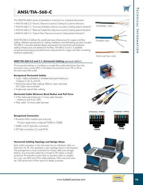
Unshielded cable<br />
Shielded cable<br />
Multimode fiber cable<br />
T echnical i nformaT ion<br />
<strong>ANSI</strong>/<strong>TIA</strong>-<strong>568</strong>-C.0 and C.1: Horizontal Cabling (previously <strong>568</strong>-B.1)<br />
The horizontal cabling in a building is a single floor cable distribution from the<br />
horizontal cross connect (HC) in the telecommunications room (TR or TE) to<br />
the work area (WA) outlet.<br />
Recognized Horizontal Cables<br />
• 4-pair 100W unshielded or shielded balanced twisted pair,<br />
Category 3, 5e, 6, and 6A<br />
• Multimode optical fiber cabling: 850mm, laser optimized<br />
50/125mm recommended<br />
• Singlemode optical fiber cabling<br />
Horizontal Cable Minimum Bend Radius and Pull Force<br />
• 4-Pair balanced twisted pair: 4 times cable diameter<br />
- Maximum pull force: 25lb<br />
• Fiber cable: 10 times cable diameter<br />
Recognized Connectors<br />
• 8-position RJ45 modular jack and plug<br />
- Pin/pair assignments configured T<strong>568</strong>A or T<strong>568</strong>B<br />
• <strong>568</strong>SC and ST-style fiber connectors<br />
• SFF fiber connectors: LC and MT-RJ<br />
Horizontal Cabling Topology and Design Notes<br />
Each outlet connection in the work area has an individual cable run<br />
(link) from the TR. This represents a star topology shown in the diagram.<br />
This arrangement is most convenient for moves, adds and changes<br />
(MACs). Any horizontal cable link is limited to 90 meters in length.<br />
Locate the TR centrally on each floor to equalize cable run lengths.<br />
As a rule, use 40% max fill for cable pathways. Allow one work area<br />
per 100 square foot of floor space for design purposes.<br />
www.hubbell-premise.com<br />
V6