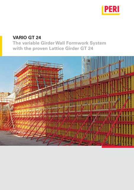
VARIO GT 24 The variable Girder Wall Formwork System with ... - Peri
VARIO GT 24 The variable Girder Wall Formwork System with ... - Peri
VARIO GT 24 The variable Girder Wall Formwork System with ... - Peri
- No tags were found...

Create successful ePaper yourself
Turn your PDF publications into a flip-book with our unique Google optimized e-Paper software.
<strong>VARIO</strong> <strong>GT</strong> <strong>24</strong><br />
<strong>The</strong> <strong>variable</strong> <strong>Girder</strong> <strong>Wall</strong> <strong>Formwork</strong> <strong>System</strong><br />
<strong>with</strong> the proven Lattice <strong>Girder</strong> <strong>GT</strong> <strong>24</strong>
Content<br />
Page<br />
Edition 09/2011<br />
PERI GmbH<br />
<strong>Formwork</strong> Scaffolding Engineering<br />
P.O. Box 12 64<br />
89259 Weissenhorn<br />
Germany<br />
Tel +49 (0)7309.950-0<br />
Fax +49 (0)7309.951-0<br />
info@peri.com<br />
www.peri.com<br />
Which <strong>Wall</strong> <strong>Formwork</strong> <strong>System</strong><br />
<strong>Girder</strong> or panel formwork<br />
<strong>VARIO</strong> <strong>GT</strong> <strong>24</strong> or TRIO 1 – 3<br />
General<br />
<strong>The</strong> <strong>variable</strong> girder wall formwork system 4 –7<br />
Complicated geometries <strong>with</strong> standard<br />
system components 8 – 9<br />
<strong>The</strong> <strong>GT</strong> <strong>24</strong> lattice girder 10 – 11<br />
<strong>The</strong> standard system components of a<br />
<strong>VARIO</strong> <strong>GT</strong> <strong>24</strong> panel 12 – 13<br />
Standard Applications<br />
<strong>VARIO</strong> <strong>GT</strong> <strong>24</strong> standard panels 14 – 15<br />
Continuously adjustable panel connection 16 – 17<br />
Fillers, stopend formwork and<br />
panel width extension units 18 – 19<br />
External corners, internal corners<br />
and shafts 20 – 21<br />
Push-pull prop connector, crane splices,<br />
safety precaution 22 – 23<br />
Working and Concreting Scaffold <strong>24</strong> – 25<br />
Panel extensions 26 – 27<br />
Special applications<br />
Important Notes:<br />
Without exception, all current safety regulations<br />
must be observed in those countries where our<br />
products are used.<br />
<strong>The</strong> illustrations in this brochure are photographs<br />
of real site situations. Safety or formwork anchor<br />
details are therefore not to be taken as a definitive<br />
guide to the way the equipment is to be used.<br />
Architectural concrete 28 – 31<br />
Bridge-building 32 – 35<br />
Water retaining structures 36 – 39<br />
Single sided walls 40 – 41<br />
Components 42 – 67<br />
PERI International 68 – 69<br />
2<br />
Close attention must be paid to safety instructions<br />
and load specifications at all times. Separate structural<br />
calculations are required for any deviations<br />
from the standard design data.<br />
<strong>The</strong> information contained herein is subject to<br />
technical changes in the interests of progress.<br />
Errors and typographical mistakes reserved.
Which <strong>Wall</strong> <strong>Formwork</strong> <strong>System</strong><br />
<strong>Girder</strong> or panel formwork<br />
<strong>VARIO</strong> <strong>GT</strong> <strong>24</strong> or TRIO<br />
PERI offers a variety of systems to<br />
enable you to choose the moste<br />
conomical for your purposes.<br />
It is always worth carrying out a<br />
cost-effectiveness comparis on for<br />
larger building projects.<br />
<strong>VARIO</strong> <strong>GT</strong> <strong>24</strong> being used for housing project.<br />
TRIO formwork for industrial building.<br />
This table will help you select the<br />
right formwork system.<br />
Each site and shape of building has its own<br />
critical parameters for a comparison of costeffectiveness:<br />
<strong>VARIO</strong><br />
<strong>GT</strong> <strong>24</strong><br />
TRIO<br />
Type of layout<br />
<strong>Wall</strong> heights<br />
Concrete Pressure<br />
Tolerances<br />
(DIN 18202)<br />
Ties<br />
Concrete <strong>with</strong> special<br />
surface finish requirements<br />
Plywood<br />
Utilisation<br />
Utilisation period<br />
consistent<br />
very <strong>variable</strong><br />
consistent<br />
very <strong>variable</strong><br />
Anchor patterns<br />
Type<br />
Size<br />
Butt joint<br />
low over short construction period<br />
high over short construction period<br />
low over long construction period<br />
high over long construction period<br />
long<br />
short<br />
x<br />
x<br />
versatile<br />
30–100 kN/m 2<br />
versatile<br />
depending<br />
on design<br />
may be<br />
optimised<br />
as required<br />
x<br />
x<br />
x<br />
x<br />
x<br />
x<br />
x<br />
x<br />
x<br />
x<br />
x<br />
60 or<br />
80 kN/m 2<br />
Table 3<br />
line 6 or 7<br />
fixed,<br />
depends on<br />
size of panels<br />
only <strong>with</strong><br />
TRIO Structure<br />
x<br />
x<br />
x<br />
x x indicates the more suitable system<br />
1
Which <strong>Wall</strong> <strong>Formwork</strong> <strong>System</strong><br />
<strong>Girder</strong> or panel formwork<br />
<strong>VARIO</strong> <strong>GT</strong> <strong>24</strong> or TRIO<br />
<strong>The</strong> architecture of high-class buildings<br />
and complicated layouts often<br />
requires custom formwork.<br />
PERI <strong>VARIO</strong> <strong>GT</strong> <strong>24</strong> readily allows<br />
any configuration to be constructed<br />
using a small number of special<br />
steel walers.<br />
11,87<br />
12,83<br />
Lift shafts for a 26-storey<br />
skyscraper in Paris.<br />
<strong>The</strong> high flexural stiffness of<br />
<strong>VARIO</strong>’s <strong>GT</strong> <strong>24</strong> girders and matching<br />
steel walers can often be<br />
used to speed up shuttering, by<br />
optimising the formwork panels<br />
and minimising the number of<br />
tie points.In many cases the<br />
<strong>VARIO</strong> system yields the most<br />
cost-effective solution. It is important<br />
to work out the overall price,<br />
reflecting both materials and<br />
labour.<br />
With <strong>VARIO</strong> <strong>GT</strong> <strong>24</strong> the cost of basic<br />
assembly and dismantling of the<br />
panels, formlining and special walers<br />
has to be spread over the number of<br />
months for which the formwork is<br />
used.<br />
<strong>The</strong> lower cost of materials <strong>with</strong><br />
<strong>VARIO</strong> makes the system particularly<br />
economical where labour is cheap.<br />
Typical <strong>VARIO</strong> applications include<br />
the stairwells of multistorey buildings,<br />
dividing walls in large blocks<br />
of flats and custom formwork (see<br />
examples <strong>with</strong> girder formwork on<br />
pages 2<strong>24</strong> and 225 of the handbook).<br />
TRIO panel formwork has the advantage<br />
of versatility for frequently<br />
changing heights and layouts.<br />
2
3,60<br />
3,60<br />
<strong>VARIO</strong><br />
One-off costs spread<br />
over number of<br />
months, plus monthly<br />
hire charge/m 2<br />
One-off costs <strong>VARIO</strong><br />
consisting of cost of<br />
basic assembly and<br />
dismantling of panels<br />
53,00<br />
5,00<br />
€ 58,00<br />
€ 53,00<br />
55,-<br />
50,-<br />
Cost of materials per time formwork used, as a function of construction period<br />
and number of times used each month (2/m 2 of concrete)<br />
58,00<br />
TRIO<br />
TRIO monthly hire<br />
charge 2/m 2 : 16.50<br />
custom walers, small<br />
components, replacement<br />
formlining<br />
€ 21,50<br />
€ 31,70<br />
<strong>VARIO</strong> costs<br />
when used once a month<br />
35,-<br />
30,-<br />
31,44<br />
25,-<br />
20,-<br />
22,50<br />
15,-<br />
16,50<br />
18,15<br />
15,59<br />
TRIO costs<br />
when used once a month<br />
10,-<br />
14,52<br />
<strong>VARIO</strong> costs<br />
when used 4 times a month<br />
13,55<br />
12,53<br />
11,50<br />
10,74<br />
5,-<br />
4,10<br />
7,87<br />
5,62<br />
4,55<br />
TRIO costs<br />
when used 4 times a month<br />
0 1 2 3 4 5 6 7 8 9 10<br />
3,89<br />
3,39<br />
3,13 2,87 2,68<br />
Months<br />
<strong>The</strong> table of costs is based on the layout shown above (height 3.60 m). <strong>VARIO</strong> and TRIO were based on the same<br />
hire charge percentages. <strong>The</strong> chart shows that in terms of materials <strong>VARIO</strong> is particularly cost-effective for long<br />
construction periods. In calculating the overall price please allow for the saving in labour costs <strong>with</strong> <strong>VARIO</strong>.<br />
This amounts to about 0.1 h ≈ € 2.50 per m 2 of concrete surface area, each time the formwork is reused.<br />
3
General<br />
<strong>The</strong> <strong>variable</strong> girder wall formwork system<br />
<strong>VARIO</strong> <strong>GT</strong> <strong>24</strong>, the girder wall<br />
formwork system <strong>with</strong> the continuously<br />
adjustable slot coupling.<br />
From industrial structures to housing,<br />
bridge abutments to retaining<br />
walls, PERI <strong>VARIO</strong> shutters any<br />
layout and height up to 18 m <strong>with</strong><br />
a single unit.<br />
<strong>The</strong> <strong>GT</strong> <strong>24</strong>’s 30 cm<br />
increments make it<br />
easier to adjust to the<br />
required height.<br />
11.50 m high walls shuttered<br />
<strong>with</strong> single unit <strong>with</strong> extralong<br />
and extended <strong>GT</strong> <strong>24</strong> girders.<br />
4
Extended <strong>VARIO</strong> panels being<br />
used to shutter administration<br />
building.<br />
Simple planning, lower stock levels<br />
and fast, economical shuttering<br />
sequence.<br />
1,05<br />
1,48<br />
GB 80 GB 80<br />
<strong>VARIO</strong> <strong>GT</strong> <strong>24</strong> formwork is used to<br />
assemble exactly the right large<br />
panel for each project.<br />
<strong>The</strong> following parameters can therefore<br />
always to be freely selected:<br />
– type and size of the plywood<br />
– plywood fixings<br />
– panel widths and heights<br />
– position of any extension or<br />
reduction in height<br />
– girder length and spacing<br />
– waler position, profile and length<br />
– permissible fresh concrete<br />
pressure<br />
– vertical and horizontal tie spacing<br />
– Type of panel: straight, curved or<br />
angled<br />
1,48<br />
1,48<br />
11,50<br />
1,51<br />
1,48<br />
1,48<br />
RS 1000<br />
<strong>VARIO</strong> <strong>GT</strong> <strong>24</strong> being used in<br />
Korea to construct a settlement<br />
tank <strong>with</strong> tapered walls.<br />
RSS III<br />
1,48<br />
AV for<br />
RSS III<br />
Section of photo at the bottom of page 4.<br />
0,45<br />
5
General<br />
<strong>The</strong> <strong>variable</strong> girder wall formwork system<br />
10.7 m high walls <strong>with</strong> doubly<br />
extended <strong>VARIO</strong> formwork.<br />
<strong>The</strong> formwork is extended <strong>with</strong><br />
the <strong>VARIO</strong> extension splice <strong>24</strong>.<br />
Quickly and easily fitted through the<br />
latticework of the <strong>GT</strong> <strong>24</strong>, <strong>with</strong>out<br />
having to drill girders.<br />
<strong>The</strong> flexurally stiff connection aligns<br />
the girders (see page 26).<br />
<strong>The</strong> splice consists of just two<br />
components, which are quickly<br />
connected <strong>with</strong> three-wing nuts.<br />
6<br />
4.20 m high <strong>VARIO</strong><br />
<strong>with</strong> bulkhead fitted.
6.00 m high <strong>VARIO</strong> <strong>GT</strong> <strong>24</strong><br />
standard panels <strong>with</strong> platform.<br />
2,71<br />
0,50 2,37<br />
Soundproof sealing of the<br />
tie points costs 50% less,<br />
since the top tie point is<br />
above the concrete <strong>with</strong><br />
waler spacing of 2.37 m.<br />
<strong>VARIO</strong> panels, <strong>with</strong> concreting<br />
platform and pushpull<br />
props, are shifted as a complete<br />
unit.<br />
7
General<br />
Even complicated geometries shuttered<br />
<strong>with</strong> standard system components<br />
<strong>VARIO</strong> <strong>GT</strong> <strong>24</strong> is particularly<br />
versatile when constructing<br />
complicated layouts, such as<br />
bridge abutments.<br />
Piers and abutment walls<br />
of a motorway bridge<br />
<strong>with</strong> <strong>VARIO</strong> <strong>GT</strong> <strong>24</strong>.<br />
Complicated abutment<br />
<strong>with</strong> <strong>VARIO</strong> <strong>GT</strong> <strong>24</strong>. Easy<br />
adjustment thanks to<br />
<strong>GT</strong> <strong>24</strong> girders and steel<br />
walers.<br />
8
<strong>The</strong> stringent French safety standards<br />
for highrise construction were<br />
taken into account in planning the<br />
formwork. <strong>The</strong>y included fine wire<br />
mesh panels for all safety handrails,<br />
and end handrail swing frames for<br />
the outside climbing units, in order<br />
to maximise the protection against<br />
falling, even during climbing.<br />
Multistorey building in<br />
Paris, <strong>with</strong> <strong>VARIO</strong> <strong>GT</strong> <strong>24</strong><br />
and CB <strong>24</strong>0 climbing<br />
formwork system.<br />
11,05<br />
Even for this complicated,<br />
circular layout over 90%<br />
of the formwork consists<br />
of standard system components.<br />
<strong>VARIO</strong> <strong>GT</strong> <strong>24</strong> being used<br />
to construct a circular tank.<br />
Timber wedges between<br />
girders and steel walers<br />
produce the circular shape.<br />
9
General<br />
<strong>The</strong> <strong>GT</strong> <strong>24</strong> lattice girder<br />
Successful building contractors<br />
use this girder from PERI because<br />
it is:<br />
Light and manageable for slabs<br />
Strong enough for wall formwork<br />
Cost-effective for customized<br />
formwork solutions<br />
<strong>The</strong> formwork girder as the main<br />
component of slab and wall formworkt<br />
ends to determine whether<br />
your forms are cost effective.<br />
Rather than the initial outlay, it is<br />
the service life and handling costs<br />
that are crucial.<br />
<strong>The</strong> <strong>GT</strong> <strong>24</strong> from PERI<br />
guarantees both:<br />
– Durability<br />
– shorter shuttering times<br />
<strong>GT</strong> <strong>24</strong> Schalungsträger<br />
Einer für Alles<br />
You can find further information<br />
in the <strong>GT</strong> <strong>24</strong> brochure.<br />
Designed to last by timber<br />
specialists. <strong>The</strong> patented chord<br />
<strong>with</strong> finger joints has practically no<br />
cavities that could trap water.<br />
<strong>The</strong> latticework is well ventilated<br />
even while the girders are stacked.<br />
Comparison<br />
<strong>with</strong> <strong>GT</strong> <strong>24</strong><br />
Permissible<br />
reaction<br />
VT 20<br />
22 kN<br />
<strong>GT</strong> <strong>24</strong><br />
28 kN*<br />
Diff. %<br />
+27%<br />
Permissible<br />
bending moment<br />
5 kNm<br />
7 kNm*<br />
+40%<br />
Flexural strength<br />
429 kN/m 2<br />
800 kN/m 2<br />
+86%<br />
Weight<br />
5,9 kg/m<br />
5,9 kg/m<br />
± 0%<br />
10<br />
*can even be supported at the node
High load-bearing capacity <strong>with</strong><br />
low weight<br />
Perm. strut shear Q S<br />
= 14 kN<br />
Perm. bending moment M = 7 kNm<br />
Prin. mom. of inertia ly = 8000 cm 4<br />
6 x 8 cm chord timber<br />
For ease of screwing and nailing.<br />
To prevent splitting, the full depth of<br />
the chord is finger jointed to the struts<br />
and tied at each girder connection.<br />
PERI tables for slab and wall<br />
formwork and German Building<br />
Regulations approval Z - 9.1 - 157<br />
are available.<br />
Colour code<br />
<strong>The</strong> common lengths of the <strong>GT</strong> <strong>24</strong><br />
girder are colour coded for ease of<br />
handling in the yard and on site.<br />
Length Colour<br />
270<br />
300<br />
330<br />
360<br />
390<br />
Steel end caps <strong>with</strong> through rivet<br />
– Robust end protection<br />
– Prevents end being sawn off<br />
accidentally<br />
– Can be used to replace rubbing<br />
board on <strong>VARIO</strong> panels when<br />
required<br />
Many customers have confirmed<br />
how long the <strong>GT</strong> <strong>24</strong> lasts.<br />
Mark of conformity<br />
Year of manufacture<br />
Day of production<br />
Length in cm (rounded off)<br />
Eberhard Claus, Shuttering Manager for Max Giese<br />
GmbH in Trappenkamp: “<strong>The</strong> <strong>GT</strong> <strong>24</strong>, is virtually indestructible<br />
this is an example manufactured in 1985.”<br />
<strong>The</strong> fact that the markings are still legible is proof that<br />
<strong>The</strong> <strong>GT</strong> <strong>24</strong> really lasts!<br />
<strong>The</strong> <strong>GT</strong> <strong>24</strong> lattice girder -<br />
the one that cuts shuttering costs.<br />
11
General<br />
<strong>The</strong> standard system components<br />
of a <strong>VARIO</strong> <strong>GT</strong> <strong>24</strong> panel.<br />
<strong>The</strong> <strong>GT</strong> <strong>24</strong> formwork girder<br />
Forms the main element of the<br />
<strong>VARIO</strong> wall formwork. Available in<br />
lengths from 90 cm to 17.80 m, in<br />
30 cm increments.<br />
Cross-section<br />
80<br />
60<br />
<strong>24</strong>0<br />
296 163<br />
28<br />
296 311<br />
Steel waler SRZ / SRU<br />
Available in standard lengths and<br />
any special sizes and forms. U 100<br />
to U 140 channel and other sections.<br />
<strong>VARIO</strong> steel waler and<br />
Internal Corner Waler IRZ<br />
for corner panels.<br />
12
Plywood<br />
<strong>The</strong> right plywood for every requirement.<br />
PERI plywood is available in<br />
various sizes, thickness and grades,<br />
so that the site always has the<br />
correct formlining available.<br />
Connecting parts<br />
Hook Strap HB <strong>24</strong><br />
for connecting <strong>GT</strong> <strong>24</strong> to SRZ<br />
and SRU.<br />
Hook Strap Uni HBU<br />
for connecting <strong>GT</strong> <strong>24</strong> to SRZ<br />
and SRU.<br />
TSS Torx screw<br />
for fixing the formlining.<br />
13
Standard Applications<br />
<strong>VARIO</strong> <strong>GT</strong> <strong>24</strong> standard panels<br />
Fully pre-assembled <strong>VARIO</strong> <strong>GT</strong> <strong>24</strong><br />
standard hire panels, covered <strong>with</strong><br />
21 mm formlining. <strong>The</strong> ready-foruse<br />
wall formwork for any height<br />
and width.<br />
<strong>The</strong> standard <strong>VARIO</strong> panels are<br />
assembled from tried and tested<br />
<strong>VARIO</strong> system components.<strong>The</strong><br />
panels are supplied complete <strong>with</strong><br />
lifting eyes and rubbing board.<br />
Permissible fresh concrete pressure:<br />
60 kN/m 2 <strong>with</strong> tie spacings 55/140/55 or<br />
50 kN/m 2 <strong>with</strong> tie spacings 62.5/125/62.5<br />
according to DIN 18202, Table 3, Line 7.<br />
Top cover board for protecting<br />
against concrete splashes, and<br />
integral crane lifting point unit.<br />
<strong>VARIO</strong> <strong>GT</strong> <strong>24</strong> standard elements complete<br />
<strong>with</strong> platforms.<br />
6,00<br />
5,40<br />
2,40<br />
Height increments<br />
<strong>VARIO</strong> standard panels are available<br />
in 60 cm height increments.<br />
<strong>The</strong>se panels are simply extended<br />
for greater heights.<br />
Base panel for<br />
extension,<br />
<strong>with</strong>out top cover.<br />
2,40<br />
0,48 1,18<br />
2,99<br />
3,00<br />
0,48 1,78<br />
3,58<br />
3,60<br />
0,48 1,18 1,18<br />
4,18<br />
4,20<br />
0,48 1,18 1,18 1,18<br />
4,77<br />
4,80<br />
0,48 1,18 1,18 1,18<br />
5,36<br />
0,48 1,18 1,18 1,18 1,18<br />
5,95<br />
0,48 1,18 1,18 1,18 1,18<br />
14
Standard panels customised<br />
for 9 m highwalls of tunnel<br />
project.<br />
<strong>System</strong> width<br />
<strong>VARIO</strong> standard panels are<br />
available in 4 widths:<br />
2,50<br />
0,625 1,25 0,625<br />
<strong>VARIO</strong> standard internal corners<br />
<strong>The</strong> consistent leg length of 75 cm<br />
allows this design to be used as a<br />
left-hand or right-hand corner.<br />
1,875<br />
0,625 0,625<br />
0,625<br />
0,75<br />
1,25<br />
0,625 0,625<br />
0,75<br />
1,00<br />
<strong>VARIO</strong> standard internal corner<br />
is available in 5 heights:<br />
2.40, 3.00,3.60, 4.80 and<br />
6.00 m.<br />
15
Standard Applications<br />
Continuously adjustable panel connection<br />
<strong>The</strong> rows of slots in the PERI<br />
steel walers and couplings allow<br />
continuous tightening of panel<br />
joints of even roughly erected<br />
panels.<br />
<strong>The</strong> <strong>VARIO</strong> coupling also aligns<br />
the panels.<br />
<strong>The</strong> multifunctional <strong>VARIO</strong> coupling<br />
using wedges:<br />
– Continuously tightens until joint<br />
grout-tight<br />
– Aligns panels<br />
– Supports plywood fillers<br />
– Extends width of panels<br />
– Holds bulkheads<br />
– Stabilises internal corners<br />
– Is independently adjustable on<br />
both sides<br />
Important:<br />
To eliminate the effect of tolerances<br />
and optimise panel joint alignment,<br />
the notches in the slots of PERI<br />
steel walers and couplings must<br />
always point towards the concrete<br />
side.<br />
Standard joint<br />
<strong>The</strong> continuous adjustment available<br />
allows grout-tight panel joints.<br />
Concrete side<br />
Concrete side<br />
Steel Waler SRZ<br />
Concrete side<br />
Concrete side<br />
<strong>VARIO</strong> coupling<br />
Filler joint<br />
Any gap up to 1.25m wide can be<br />
filled.<br />
Internal corner<br />
<strong>The</strong> same <strong>VARIO</strong> coupling as for the<br />
straight joint can be used forthe<br />
internal corner.<br />
Oblique joint<br />
Any angle can be shuttered <strong>with</strong> the<br />
articulated coupling.<br />
16
Easy connection of panels <strong>with</strong><br />
PERI <strong>VARIO</strong> <strong>GT</strong> <strong>24</strong>:<br />
1. Insert coupling centrally <strong>with</strong> the<br />
notches towards the formlining,<br />
and centre <strong>with</strong>wedge 4.<br />
2. On one side, hammer the first<br />
wedge 1 into the 1st slot, andthe<br />
second wedge 2 into the 6th slot,<br />
<strong>with</strong> a gap of 4 slotsbetween<br />
them.<br />
3. To achieve a spacing of 5 cm<br />
between the two steel walers,<br />
the centering wedge 4 remains<br />
inserted until you have pulled the<br />
formlining joint grout-tight<strong>with</strong><br />
wedge 3.<br />
4. Remove the centering wedge 4<br />
and insert it in the locking position<br />
in the sixth slot. This ensures the<br />
joint can resisttension and compression,<br />
and brings the panels<br />
into tight, flush alignment.<br />
5<br />
<strong>The</strong> panel connection is finished<br />
Practical tip<br />
Whether a wedge is locking or pulling<br />
is evident from its inclination:<br />
Tip of wedge towards the panel joint<br />
= wedge pulling<br />
Tip of wedge away from panel joint<br />
= wedge locking<br />
wedge locking<br />
wedge pulling<br />
17
Standard Applications<br />
Fillers, stopend formwork<br />
and panel width extension units<br />
Infill areas<br />
Infills are shuttered <strong>with</strong> <strong>VARIO</strong><br />
<strong>GT</strong> <strong>24</strong>, using the <strong>VARIO</strong> couplings<br />
VKZ 147 and VKZ 211.<br />
Coupling VKZ<br />
Wedge K<br />
Coupling Compression<br />
Plate<br />
KDP<br />
Maximum width extensions <strong>with</strong><br />
<strong>VARIO</strong> couplings VKZ<br />
(see table for <strong>VARIO</strong> fillers)<br />
Continuously adjustable<br />
fillers <strong>with</strong> <strong>VARIO</strong> couplings.<br />
max. 0,48 m<br />
VKZ 147<br />
VKZ 211<br />
max. 1,20 m<br />
18
Stopend <strong>Formwork</strong><br />
<strong>VARIO</strong> offers two ways of forming<br />
stopends.<br />
Permissible wall thickness x [m]<br />
for stopends <strong>with</strong> VKZ<br />
1.<strong>VARIO</strong> coupling VKZ<br />
perm. tension force 50 kN<br />
<strong>VARIO</strong> coupling VKZ 99<br />
Item No. 013010<br />
x<br />
Spacer timber by site<br />
x<br />
Important:<br />
Pulling wedge must be inserted in<br />
the first hole.<br />
2. With Stopend Tie<br />
perm. tension force 30 kN<br />
Stopend Tie<br />
Item-no. 013<strong>24</strong>0<br />
Panel <strong>with</strong> extensions<br />
Complete bulkhead <strong>with</strong><br />
stopend tie.<br />
Even panel width extensions<br />
are solved using<br />
standard <strong>VARIO</strong> system<br />
components.<br />
19
Standard Applications<br />
External corners, internal corners and shafts<br />
Depending on the application,<br />
external and internal corners can<br />
be formed in various alternative<br />
ways.<br />
– With <strong>VARIO</strong> corner panel<br />
– With cross waler & shaft corner<br />
– With special walers<br />
<strong>VARIO</strong> corner panel<br />
With this solution, especially for thin<br />
walls and low utilisation, the fillers<br />
are made from standard components.<br />
External: Panel width = 2.50 m<br />
1 panel <strong>with</strong> width extension unit<br />
Internal: Panel width = 1.25/1.50 m<br />
and panel width = 1.25 m <strong>with</strong> filler.<br />
Example for filler x:<br />
d 1 = 30 cm<br />
x = 250 cm – 125 cm – 50 cm –<br />
30 cm – 2 cm formlining<br />
x = 43 cm<br />
Internal corner<br />
Detail <strong>VARIO</strong> corner<br />
External corner<br />
<strong>VARIO</strong> internal corner <strong>with</strong> filler.<br />
d 1<br />
It’s a matter of pulling tight at the<br />
correct angle. No problem <strong>with</strong> the<br />
continuous adjustment of <strong>VARIO</strong><br />
<strong>GT</strong> <strong>24</strong>.<br />
<strong>The</strong> waler on the panel width extension<br />
unit must project 2 cm to enable firm<br />
pretensioning of the corner.<br />
1,25<br />
x 0,50<br />
d 1<br />
20
Shafts<br />
Small shafts can be solved<br />
particularly cost-effectively <strong>with</strong><br />
cross walers customised for<br />
the project, and the quick<br />
release corner SSE.<br />
Detail:<br />
Safety quick release corner<br />
150<br />
150<br />
21<br />
Practical tip:<br />
Pull shaft corner tight no<br />
later than the next day.<br />
Small lift shaft <strong>with</strong> cross<br />
walers and safety quick<br />
release corner SSE.<br />
21
Standard Applications<br />
Push-pull prop connector, crane splices<br />
Connection to <strong>GT</strong> <strong>24</strong> girder <strong>with</strong><br />
girder head piece, Item no 028050.<br />
Push-pull prop connection<br />
Arrange push-pull props and kickers<br />
as shown on the diagram and in the<br />
table below. Connect to the <strong>VARIO</strong><br />
panel <strong>with</strong><br />
the girder head piece<br />
Item no 028050 or the<br />
wedge head pieceI<br />
tem no 028060. Connect to the slab<br />
<strong>with</strong> the<br />
matching base plate and PERI<br />
Anchor Bolt MMS 20x130,<br />
Item no.: 103606.<br />
<strong>The</strong> first panel must always be<br />
secured <strong>with</strong> 2 push-pull props.<br />
See table for further props.<br />
Connection to steel waler SRZ <strong>with</strong><br />
wedge head piece, Item no 028060<br />
and wedge K, Item no 0<strong>24</strong>250.<br />
picture 1<br />
h<br />
0,5 kN/m 2<br />
y<br />
FRS<br />
picture 1<br />
picture 2<br />
<strong>Formwork</strong> Height h [m]<br />
3,0 4,0 5,0 6,0 7,0 8,0 9,0 10,0 11,0 12,0<br />
max. Width of influence [m] 3,53 2,73 2,19 1,82 1,58 1,42 1,9 1,9 1,4 1,3<br />
Actual prop load F F RS1<br />
RS<br />
[kN]<br />
9,4 9,4 11,3 11,3<br />
at maximum prop spacing 9,7 9,7 9,8 9,8 9,8 9,6<br />
F RS2<br />
9,5 9,5 9,3 10,1<br />
Actual kicker load F AV<br />
[kN]<br />
2,1 2,3 2,2 2,2 2,3 2,6 2,6 2,6 2,1 1,9<br />
at maximum prop spacing<br />
x 4,3 4,3<br />
x =<br />
Dist. of base plate [m] from<br />
1<br />
5,3 5,9<br />
front face of formwork 1,2 1,6 2,0 2,4 2,9 3,5<br />
x 2<br />
2,6 2,6 2,8 3,0<br />
y = *Top connection point [m]<br />
y 1<br />
1,5 1,5 1,8 1,8<br />
1,0 1,2 1,5 1,8 2,0 2,0<br />
from top of formwork<br />
y 2<br />
4,5 4,5 6,2 6,9<br />
*If neccessary, the distances must be adapted to the existing<br />
formwork system.<br />
A maximum force of 11.3 kN is to be transfered into the building<br />
at the base of the push-pull prop for the given width of influence.<br />
Wind Loads: h < 8 m = 0,5 kN/m 2<br />
8 m h < 20 m = 0,8 kN/m 2<br />
22<br />
Permissible widths of load<br />
h<br />
0,5 kN/m 2 0,8 kN/m 2<br />
F AV<br />
60°<br />
x<br />
picture 2<br />
F AV<br />
y 1<br />
y 2<br />
FRS 1<br />
FRS 2<br />
60° 60°<br />
x 2<br />
x 1
Crane Suspension<br />
PERI <strong>VARIO</strong> offers two units for<br />
lifting panels <strong>with</strong> the crane:<br />
1. <strong>The</strong> crane splice <strong>24</strong><br />
easily fitted and removed.<br />
2. <strong>The</strong> crane lifting eye <strong>24</strong>,<br />
right/left<br />
integral lifting unit.<br />
Important:<br />
Always used two crane lifting point<br />
units for each unit to be shifted!It is<br />
essential to follow the<br />
Instructions for Use, which contain<br />
important information!<br />
Kranlasche <strong>24</strong><br />
Art.-Nr. 070760<br />
Betriebsanleitung<br />
Ausgabe 05/2007<br />
Instructions for Use<br />
of the crane splice <strong>24</strong>.<br />
Customized assembly,<br />
a <strong>VARIO</strong> <strong>GT</strong> <strong>24</strong> element<br />
ready for use.<br />
Crane Splice <strong>24</strong><br />
Safe working load of 700 kg, <strong>with</strong><br />
legs of sling at a maximum<br />
inclination of 15° to the vertical.<br />
Crane lifting eye <strong>24</strong>, right/left<br />
Safe working load of 700 kg, <strong>with</strong><br />
legs of sling at a maximum<br />
inclination of 15° to the vertical.<br />
23
Standard Applications<br />
Working and Concreting Scaffold<br />
Scaffold Bracket GB 80<br />
Scaffold components supplied by<br />
the contractors must correspond<br />
to valid safety regulations!<br />
(for Germany DIN 4420)<br />
Timber components must conform<br />
at least to S10 or MS10 classific<br />
ationaccording to DIN 4074<br />
as well as being clearly marked<br />
(BGR 169)!<br />
Cross-section of guardrail boards:<br />
3 cm x 15 cm!<br />
Secure planking and guardrails<br />
<strong>with</strong> nails or screws!<br />
A concreting platform<br />
conforming to the<br />
regulations, <strong>with</strong> PERI<br />
end handrail frame 55,<br />
Item no 065066.<br />
PERI platform bracket GB 80 for an<br />
approyimately 80 cm wide work<br />
platformPermissible Load: 150kg/m 2<br />
Max. Allowable Spacing: 1.25m<br />
<strong>24</strong><br />
Several work platform<br />
levels are required for<br />
high formwork.
<strong>VARIO</strong> platform system<br />
Pre-assembled concreting/working<br />
platforms in different widths. Complete<br />
<strong>with</strong> guardrails, end handrail<br />
frame, push-pull prop connections<br />
and crane eye. With or <strong>with</strong>out<br />
access hatch.<br />
Platform safety handrail<br />
frames 80<br />
<strong>VARIO</strong> platform<br />
100/250 <strong>with</strong> hatch<br />
<strong>VARIO</strong> platform<br />
Bulit-in crane lifitng<br />
point unit<br />
Ladder 2.40 – 2.70<br />
3,00 m<br />
Platform Brace 167<br />
Platform connector<br />
Push-pull prop<br />
<strong>VARIO</strong> platform<br />
100/250 <strong>with</strong> hatch<br />
Push-pull prop RSS III<br />
5.40 m high <strong>VARIO</strong> standard<br />
panels ready for use. With<br />
concreting platforms, ladders<br />
and push-pull props.<br />
<strong>The</strong> permissible load of the <strong>VARIO</strong><br />
platform is 1,5 kN/m 2 . <strong>The</strong> crane lifting<br />
point unit is incorporated in the<br />
platforms.<br />
25
Standard Applications<br />
Panel extensions<br />
Panels may be extended <strong>with</strong> the<br />
<strong>VARIO</strong> extension splice <strong>24</strong> for<br />
heights up to 8.00 m.<br />
<strong>The</strong> extension splice <strong>24</strong> is quickly and easily connected<br />
through the lattice work of the <strong>GT</strong> <strong>24</strong>, <strong>with</strong>out<br />
having to drill the girders.<br />
<strong>The</strong> standard method of extension<br />
is to use the <strong>VARIO</strong> extension<br />
splice <strong>24</strong>.<br />
<strong>The</strong> flexurally stiff connection aligns<br />
the girders. <strong>The</strong> splice, which consists<br />
of just two components, is connected<br />
in no time <strong>with</strong> two quick action<br />
wingnuts.<br />
Extensions up to 8.00 m<br />
8 Extension Splices <strong>24</strong> for 2.50 m<br />
wide element.<br />
Section properties for Extension<br />
Splice <strong>24</strong><br />
M perm . = 1,73 kNm<br />
Q perm. = 0<br />
or<br />
M zul. = 0<br />
Q perm. = 5 kN<br />
Extensions up to 5.00 m<br />
4 Extension Splices <strong>24</strong> for 2.50 m<br />
wide element.<br />
60 cm high timber extension made simple <strong>with</strong> the<br />
extension splice <strong>24</strong>.<br />
min 46 min 46<br />
8,00 m<br />
5,00 m<br />
26
With overlapping girders for<br />
heights up to about 9.80 m<br />
3,85<br />
3,88 4,14<br />
2,07<br />
0,13 1,18 1,22 1,18 0,16<br />
5,95<br />
5,95<br />
11,90<br />
1,18 1,18 1,18 1,18 1,22 1,18 1,18 1,18 1,18 0,78<br />
0,46<br />
1,18 1,18 1,18 1,18 1,18 1,18 1,18 0,89 0,16<br />
0,46<br />
2,10<br />
1,18 0,76<br />
0,16<br />
5,95<br />
5,95<br />
9,80<br />
With additional girders for heights<br />
up to 11.90 m.<br />
For more information on extensions,<br />
see PERI design tables or<br />
<strong>VARIO</strong> <strong>GT</strong> <strong>24</strong> assembly instructions.<br />
11.00 m high bridge abutment <strong>with</strong> butted girders<br />
and additional overlapping girders for stiffening.<br />
27
Special applications<br />
Architectural concrete<br />
Perfect concrete finishes <strong>with</strong> <strong>VARIO</strong><br />
Achieving first-class fairfaced concrete<br />
is primarily a question of<br />
theright formwork and formlining,<br />
but other factors do play an<br />
importantrole. Accuracy of formwork<br />
assembly, shuttering, release<br />
agent, concrete and its placing all<br />
significantly effect the result.<br />
Attractive looking concrete<br />
finish <strong>with</strong> rough<br />
vertical board finish.<br />
43.50 m high tower<br />
<strong>with</strong> fairfaced concrete<br />
<strong>with</strong> a board finish<br />
foran industrial plant.<br />
28
Church steeple in Feldmoching<br />
near Munich.<br />
<strong>VARIO</strong> <strong>GT</strong> <strong>24</strong> on KGF <strong>24</strong>0<br />
climbing formwork system.<br />
Exemplary fairfaced<br />
concrete <strong>with</strong> rough<br />
horizontal board finish.<br />
Consecretion Hall,<br />
Neubiberg, Germany<br />
Germany. <strong>VARIO</strong> <strong>with</strong><br />
orderly tie pattern.<br />
Formlining screwed on<br />
from the rear.<br />
Perfect fairfaced concrete <strong>with</strong> horizontal and<br />
vertical panicular pattern.<br />
29
Special applications<br />
Architectural concrete<br />
Simple yet elegant concrete finishes<br />
Fairfaced concrete formwork <strong>with</strong><br />
simple joint pattern.<br />
<strong>VARIO</strong> <strong>GT</strong> <strong>24</strong> offers a flexible choice<br />
of waler and tie spacing for a wide<br />
variety of orderly tie patterns.<br />
2.50 x 3.60 m panel<br />
<strong>with</strong> tie spacing of 1.25 x 1.18 m.<br />
2 ties horizontally<br />
3 ties vertically<br />
2.50 x 3.60 m panel<br />
<strong>with</strong> tie spacing of 0.88 x 1.78 m.<br />
3 ties horizontally<br />
2 ties vertically<br />
3,90<br />
3,60<br />
3,60<br />
2,50<br />
2,50<br />
3.00 x 3.90 m panel<br />
Fairfaced concrete <strong>with</strong> orderly<br />
pattern of joints and tie spacing of<br />
0.75 x 1.18 m. 4 ties horizontally<br />
3 ties vertically<br />
3,00<br />
30<br />
An orderly pattern of ties<br />
spaced at 0.75 x 1.18 m<br />
and smooth fairfaced<br />
concrete are the result.<br />
Grammar school centre in<br />
Kletow, Germany.
Forming boards provided by client<br />
<strong>The</strong> rough surface finish ensures<br />
the massive tunnel portals blend<br />
into the volcanic rock landscape.<br />
<strong>The</strong> unusual washboard structure<br />
was created using extra battens<br />
on the formwork skin.<br />
High-quality fairfaced concrete<br />
<strong>with</strong> vertical board finish.<br />
<strong>The</strong> panels were preassembled in<br />
PERI’s Weissenhorn factory.<br />
Portal of a tunnel structure<br />
on Hawaii. Shuttered <strong>with</strong><br />
<strong>VARIO</strong> <strong>GT</strong> <strong>24</strong> on KGF <strong>24</strong>0<br />
climbing system.<br />
German BAB 4 motorway<br />
bridge over the valley of<br />
the Triebischbach. Circular<br />
piers up to 49 m high <strong>with</strong><br />
trumpet-shaped capitals.<br />
31
… typengeprüfte Sicherheit<br />
Special applications<br />
Bridge-building<br />
<strong>VARIO</strong> on climbing scaffolds and<br />
work platforms<br />
More informations can be<br />
found in the CB brochure.<br />
Klettergerüste CB <strong>24</strong>0 und CB 160<br />
Das Baukastensystem<br />
für alle Einsatzbereiche<br />
Type-checked safety <strong>with</strong> KGF<br />
<strong>24</strong>0, KG 180 and CB <strong>24</strong>0, CB 160<br />
systems.<br />
<strong>The</strong> KGF <strong>24</strong>0 and CB <strong>24</strong>0 carriages<br />
allow the formwork to be moved<br />
75 cm on the platform <strong>with</strong>out the<br />
crane. To save time the formwork is<br />
raised together <strong>with</strong> the scaffoldin a<br />
single lift of the crane.<br />
<strong>The</strong>se two systems ensure you can<br />
work extremely safely <strong>with</strong>out any<br />
projections (such as the brackets)<br />
above the surface of the platformto<br />
trip over.<br />
To speed up erection, the staging<br />
can be prefabricated for immediate<br />
use on site after site.<br />
0,75<br />
CB <strong>24</strong>0, the triangular<br />
bracket that readily<br />
allows you to work<br />
infront of and behind<br />
the formwork.<br />
32
Klettergerüste KGF <strong>24</strong>0 und KGF 160<br />
Mit Sicherheit, wenn´s in die Höhe geht.<br />
More informations can be<br />
found in the KG brochure.<br />
1,18 0,80 1,18<br />
6,80<br />
Motorway viaduct in France.<br />
Sophisticated pier geometry<br />
<strong>with</strong> extraordinary concrete<br />
finish. Single sided shuttering<br />
<strong>with</strong> <strong>VARIO</strong> <strong>GT</strong> <strong>24</strong> and SKS<br />
climbing brackets.<br />
On ASG 160 On folding platform FB 180<br />
Faltbühne FB 180-3<br />
Das leichte und komplett vormontierte<br />
Bühnensystem für den Betonbau<br />
More informations can<br />
be found in the FB 180<br />
brochure.<br />
max. h = 5,40 m<br />
max. h = 5,40 m<br />
ASG 160 FB 180<br />
33
Special applications<br />
Bridge-building<br />
Abutments and piers<br />
Section A-A<br />
1,00<br />
GB 80<br />
5,98<br />
RSS III<br />
Bridge abutment <strong>with</strong> <strong>VARIO</strong><br />
standard panels and infillingby<br />
client.Wittstock Inter-change on<br />
the German BAB <strong>24</strong> motorway.<br />
A<br />
9,10<br />
A<br />
6,09<br />
Ground plan<br />
9,25<br />
34
Example of a bridge pier tapered<br />
towards the top.<br />
View of long side<br />
Section A-A<br />
Concreting<br />
platform GB 80<br />
5,40<br />
Push-Pull Prop<br />
RSS III<br />
Kicker<br />
RSS III<br />
3,05<br />
2,75<br />
3,05<br />
Sides of hollow piers on the banks of<br />
the river, climbed <strong>with</strong> <strong>VARIO</strong> <strong>GT</strong> <strong>24</strong> on<br />
climbing scaffold PERI KG <strong>24</strong>0. Transition<br />
to pointed ends achieved <strong>with</strong><br />
<strong>VARIO</strong> standard components and forming<br />
boards.<br />
Bridge over the Danube.<br />
BAB 8 Motorway near<br />
Leipheim.<br />
Abutment and bridge pier<br />
<strong>with</strong> <strong>VARIO</strong> <strong>GT</strong> <strong>24</strong>.<br />
Crossing structure for the<br />
suburban railway line to<br />
the new Munich Airport.<br />
35
Special applications<br />
Water retaining structures<br />
<strong>VARIO</strong> used as single sided and tied formwork<br />
When constructing locks, dams,<br />
cooling towers and walls requiring<br />
single sided shuttering, <strong>VARIO</strong><br />
<strong>GT</strong> <strong>24</strong> is always used <strong>with</strong> KG and<br />
CB, or SKS, climbing systems.<br />
Section<br />
through SKS<br />
tie-less formwork<br />
V-Strongback SKS<br />
Compression<br />
Brace SKS<br />
Bracket SKSF <strong>24</strong>0<br />
Magdeburg Rail/Road/Waterway<br />
Interchange. A number of structures<br />
will be required in the course of this<br />
transport project. <strong>The</strong> photograph<br />
shows the Rothensee Lock.<br />
It is being shuttered <strong>with</strong> <strong>VARIO</strong> <strong>GT</strong> <strong>24</strong><br />
on climbing scaffold KG and single<br />
sided climbing scaffold SKS.<br />
Complete unit:<br />
<strong>VARIO</strong> <strong>GT</strong> <strong>24</strong> on single sided<br />
climbing scaffold SKSF <strong>24</strong>0.<br />
36
Section<br />
through KGF<br />
tied formwork<br />
GB 80<br />
Power station on the river Isar at<br />
Plattling-Pielweichs.<br />
Pier formwork <strong>with</strong> <strong>VARIO</strong> <strong>GT</strong> <strong>24</strong> in<br />
combination <strong>with</strong> circular formwork<br />
GRV.<br />
Fairfaced concrete <strong>with</strong> a vertical<br />
board finish was produced.<br />
PERI <strong>VARIO</strong> <strong>GT</strong> <strong>24</strong>’s versatility and<br />
easy adaptability makes it a particularly<br />
cost-effective shuttering system<br />
in this area.<br />
Back of the weir pier.<br />
<strong>VARIO</strong> <strong>GT</strong> <strong>24</strong> is easily<br />
matched up <strong>with</strong> the<br />
sloping rear wall.<br />
4,50<br />
Bracket<br />
KGF <strong>24</strong>0<br />
Finishing platform<br />
KGF <strong>24</strong>0<br />
Front of the weir pier. <strong>VARIO</strong><br />
in combination <strong>with</strong> circular<br />
formwork system GRV on<br />
climbing scaffold KGF <strong>24</strong>0.<br />
37
Special applications<br />
Water retaining structures<br />
Circular structures <strong>with</strong> <strong>VARIO</strong> <strong>GT</strong> <strong>24</strong><br />
Separate brochures for<br />
PERI RUNDFLEX and<br />
GRV circular formwork<br />
systems.<br />
GRV Gelenkriegel Rundschalung<br />
Zum Schalen runder<br />
Bauwerke ohne Anker<br />
RUNDFLEX<br />
Die stufenlos einstellbare Rundschalung<br />
für Radien ab 1,00 m<br />
<strong>The</strong>re are two alternative methods<br />
of shuttering circular structures<br />
<strong>with</strong> <strong>VARIO</strong> <strong>GT</strong> <strong>24</strong>.<br />
<strong>The</strong> <strong>VARIO</strong> articulated coupling connects<br />
the straight steel walers in a<br />
polygonal arrangement. Its wedges<br />
allow it to be continuously adjusted<br />
in either direction to produce a clean<br />
and flush joint between panels.<br />
Timber wedges inserted between<br />
the walers and timber girders to<br />
produce the required curvature are<br />
clamped in place <strong>with</strong> hook straps.<br />
<strong>The</strong> haunched transition<br />
to the ground slab was<br />
pre-assembled <strong>with</strong> the<br />
<strong>VARIO</strong> wall formwork<br />
panels to form a single<br />
unit for lifting.<br />
Version 1<br />
Timber wedges inserted between<br />
girders <strong>GT</strong> <strong>24</strong> and steel walers SRZ.<br />
Steel Waler SRZ Special Length<br />
Timber wedge Steel waler SRZ <strong>24</strong>5<br />
38
Version 2<br />
Segment profile timbers between<br />
formlining and girders.<br />
<strong>VARIO</strong> panel <strong>with</strong> segment<br />
profile timbers on <strong>GT</strong> <strong>24</strong> girders.<br />
7.50 high circular formwork<br />
<strong>with</strong> segment profile timbers<br />
on the <strong>GT</strong> <strong>24</strong> girders.<br />
72 m high fly ash silo <strong>with</strong> a<br />
diameter of 20m for power<br />
station in Oppeln, Poland.<br />
Shuttered <strong>with</strong> circular <strong>VARIO</strong><br />
girder formwork on climbing<br />
scaffold KGF.<br />
39
Special applications<br />
Single sided walls<br />
With <strong>VARIO</strong> and brace frame SB<br />
For concreting against rock,<br />
existing walls or sheet piling,<br />
<strong>VARIO</strong> <strong>GT</strong> <strong>24</strong> <strong>with</strong> SB brace<br />
frames is used.<br />
PERI brace frames allow single<br />
sided concreting up to a maximum<br />
height of 8.75 m (see PERI charts).<br />
PERI brace frames SB-A0, A, B and<br />
C are sized for loading on a lorry or<br />
in a container.<br />
PERI brace frames can be connected<br />
to all PERI wall formwork systems<br />
(TRIO, <strong>VARIO</strong> and RUNDFLEX) <strong>with</strong><br />
standard system components.<br />
Maximum pour height of<br />
8,75 m A0, A, B or C brace<br />
frame <strong>with</strong> <strong>VARIO</strong> <strong>GT</strong> <strong>24</strong>.<br />
<strong>The</strong> PERI V-anchor bracket<br />
For easy and accurate installation of<br />
anchors when using brace frames.<br />
<strong>The</strong> V-anchor bracket and the<br />
positioning coupling allow you to<br />
fix the anchor accurately at 45°.<br />
<strong>The</strong> advantages of the anchor system<br />
<strong>with</strong> positioning coupler and V-anchor<br />
bracket are:<br />
– few components have to be<br />
stocked<br />
– no need to cut tie rods off<br />
– tie rods recoverable.<br />
<strong>The</strong> tension forces arising at the<br />
brace frame’s anchor point determine<br />
the choice of anchor system.<br />
35<br />
Anchor system easily fixed to<br />
reinforcement <strong>with</strong> wire and pliers.<br />
<strong>The</strong> positioning coupler is removed<br />
<strong>with</strong> the 70 mm single ended spanner.<br />
Example:<br />
Anchor system DW 20:<br />
Permis. tension force to DIN 18216<br />
2 x 150 kN = 300 kN<br />
40
VITAL points when using PERI<br />
brace frames:<br />
1. <strong>The</strong> structural members (eg foundations<br />
or ground slabs) must be<br />
able to take the tension and compression<br />
forces arising.<br />
Check the design of the members<br />
and position of the anchors when<br />
planning.<br />
2. <strong>The</strong> “other side” of the single<br />
sided formwork (existing walls,<br />
planking and strutting, rock, etc)<br />
must obviously be able to <strong>with</strong>stand<br />
the fresh concrete pressure acting<br />
upon it.<br />
3. DW tie rods installed for anchoring<br />
purposes must not be welded or<br />
bent. We recommend the use of<br />
PERI V-anchor brackets.<br />
Stützbock SB<br />
Für einhäuptiges<br />
Betonieren bis 8,75 m Höhe.<br />
More informations can<br />
be found in the Brace<br />
Frames brochure.<br />
SB-C<br />
<strong>The</strong> following couplers are required<br />
for connecting <strong>VARIO</strong> <strong>GT</strong> <strong>24</strong><br />
to PERI brace frames SB-A0, A, B<br />
and C:<br />
Waler connector<br />
SB-A, B, C<br />
Item no 025760<br />
Wedge K, galv.<br />
Item no 0<strong>24</strong>250<br />
8,75<br />
SB-B<br />
Example:<br />
<strong>VARIO</strong> <strong>GT</strong> <strong>24</strong> h = 8.75 m<br />
SB-A<br />
SB-A0<br />
41
<strong>VARIO</strong> <strong>GT</strong> <strong>24</strong> <strong>Girder</strong> <strong>Wall</strong> <strong>Formwork</strong><br />
Item no. Weight kg<br />
101<strong>24</strong>1<br />
101<strong>24</strong>2<br />
101<strong>24</strong>3<br />
101<strong>24</strong>4<br />
101<strong>24</strong>5<br />
101<strong>24</strong>6<br />
101<strong>24</strong>7<br />
314,000<br />
375,000<br />
480,000<br />
586,000<br />
635,000<br />
742,000<br />
791,000<br />
<strong>VARIO</strong> Standard Panels S b = 2.50 m<br />
<strong>VARIO</strong> Standard Panel S 250 x <strong>24</strong>0<br />
<strong>VARIO</strong> Standard Panel S 250 x 300<br />
<strong>VARIO</strong> Standard Panel S 250 x 360<br />
<strong>VARIO</strong> Standard Panel S 250 x 420<br />
<strong>VARIO</strong> Standard Panel S 250 x 480<br />
<strong>VARIO</strong> Standard Panel S 250 x 540<br />
<strong>VARIO</strong> Standard Panel S 250 x 600<br />
Pre-assembled panels <strong>with</strong> 21 mm plywood. With<br />
Slip Boards, Cover Board and Crane Eye <strong>24</strong>.<br />
Note<br />
Panel = 2.40 m, <strong>with</strong>out Cover Board and Crane<br />
Eye <strong>24</strong>.<br />
Technical Data<br />
Permissible fresh concrete pressure 60 kN/m 2 .<br />
Safety Instructions<br />
Load-bearing point capacity 0.7t <strong>with</strong> a crane sling<br />
angle ≤ 15°.<br />
.<br />
2500<br />
297 350 350 350 350 350 297 78<br />
.<br />
600<br />
21<br />
625 1250 625<br />
<strong>24</strong>0<br />
100<br />
540<br />
480<br />
<strong>24</strong>0<br />
459 1184<br />
2398<br />
300<br />
459 1776<br />
2990<br />
360<br />
459 1184 1184<br />
3582<br />
420<br />
459 1184 1184 1184<br />
4174<br />
459 1184<br />
1184 1184<br />
4766<br />
459 1184 1184 1184 1184<br />
5358<br />
1184 1184 1184 1184<br />
459<br />
5950<br />
101311 6,170 Protection Board 250<br />
As top covering for <strong>VARIO</strong> <strong>GT</strong> <strong>24</strong> standard panels.<br />
<strong>24</strong>8<br />
2500<br />
21<br />
42
<strong>VARIO</strong> <strong>GT</strong> <strong>24</strong> <strong>Girder</strong> <strong>Wall</strong> <strong>Formwork</strong><br />
Item no. Weight kg<br />
101<strong>24</strong>8<br />
101<strong>24</strong>9<br />
101250<br />
101251<br />
101252<br />
101253<br />
101254<br />
235,000<br />
282,000<br />
361,000<br />
440,000<br />
477,000<br />
557,000<br />
594,000<br />
<strong>VARIO</strong> Standard Panels S b = 1.875 m<br />
<strong>VARIO</strong> Standard Panel S 187,5 x <strong>24</strong>0<br />
<strong>VARIO</strong> Standard Panel S 187,5 x 300<br />
<strong>VARIO</strong> Standard Panel S 187,5 x 360<br />
<strong>VARIO</strong> Standard Panel S 187,5 x 420<br />
<strong>VARIO</strong> Standard Panel S 187,5 x 480<br />
<strong>VARIO</strong> Standard Panel S 187,5 x 540<br />
<strong>VARIO</strong> Standard Panel S 187,5 x 600<br />
Pre-assembled panels <strong>with</strong> 21 mm plywood. With<br />
Slip Boards, Cover Board and Crane Eye <strong>24</strong>.<br />
Note<br />
Panel = 2.40 m, <strong>with</strong>out Cover Board and Crane<br />
Eye <strong>24</strong>.<br />
Technical Data<br />
Permissible fresh concrete pressure 60 kN/m 2 .<br />
Safety Instructions<br />
Load-bearing point capacity 0.7t <strong>with</strong> a crane sling<br />
angle ≤ 15°.<br />
.<br />
1875<br />
319,5 360 360 360 319,5 78<br />
.<br />
600<br />
<strong>24</strong>0 21<br />
540<br />
625 625 625<br />
100<br />
480<br />
<strong>24</strong>0<br />
459 1184<br />
2398<br />
300<br />
459 1776<br />
2990<br />
360<br />
459 1184 1184<br />
3582<br />
420<br />
459 1184 1184 1184<br />
4174<br />
459 1184<br />
1184 1184<br />
4766<br />
459 1184 1184 1184 1184<br />
5358<br />
1184 1184 1184 1184<br />
459<br />
5950<br />
101318 4,470 Protection Board 187.5<br />
As top covering for <strong>VARIO</strong> <strong>GT</strong> <strong>24</strong> standard panels.<br />
<strong>24</strong>8<br />
1875<br />
21
<strong>VARIO</strong> <strong>GT</strong> <strong>24</strong> <strong>Girder</strong> <strong>Wall</strong> <strong>Formwork</strong><br />
Item no. Weight kg<br />
101255<br />
101256<br />
101257<br />
101258<br />
101259<br />
101260<br />
101261<br />
162,000<br />
208,000<br />
265,000<br />
322,000<br />
350,000<br />
407,000<br />
435,000<br />
<strong>VARIO</strong> Standard Panels S b = 1.25 m<br />
<strong>VARIO</strong> Standard Panel S 125 x <strong>24</strong>0<br />
<strong>VARIO</strong> Standard Panel S 125 x 300<br />
<strong>VARIO</strong> Standard Panel S 125 x 360<br />
<strong>VARIO</strong> Standard Panel S 125 x 420<br />
<strong>VARIO</strong> Standard Panel S 125 x 480<br />
<strong>VARIO</strong> Standard Panel S 125 x 540<br />
<strong>VARIO</strong> Standard Panel S 125 x 600<br />
Pre-assembled panels <strong>with</strong> 21 mm plywood. With<br />
Slip Boards, Cover Board and Crane Eye <strong>24</strong>.<br />
Note<br />
Panel = 2.40 m, <strong>with</strong>out Cover Board and Crane<br />
Eye <strong>24</strong>.<br />
Technical Data<br />
Permissible fresh concrete pressure 60 kN/m 2 .<br />
Safety Instructions<br />
Load-bearing point capacity 0.7t <strong>with</strong> a crane sling<br />
angle ≤ 15°.<br />
.<br />
1<strong>24</strong>8<br />
297 180 320 297 77<br />
.<br />
600<br />
21<br />
6<strong>24</strong> 6<strong>24</strong><br />
<strong>24</strong>0<br />
100<br />
540<br />
480<br />
<strong>24</strong>0<br />
459 1184<br />
2398<br />
300<br />
459 1776<br />
2990<br />
360<br />
459 1184 1184<br />
3582<br />
420<br />
459 1184 1184 1184<br />
4174<br />
459 1184<br />
1184 1184<br />
4766<br />
459 1184 1184 1184 1184<br />
5358<br />
1184 1184 1184 1184<br />
459<br />
5950<br />
101319 2,860 Protection Board 125<br />
As top covering for <strong>VARIO</strong> <strong>GT</strong> <strong>24</strong> standard panels.<br />
<strong>24</strong>8<br />
1<strong>24</strong>8<br />
21<br />
44
<strong>VARIO</strong> <strong>GT</strong> <strong>24</strong> <strong>Girder</strong> <strong>Wall</strong> <strong>Formwork</strong><br />
Item no. Weight kg<br />
101411<br />
101410<br />
101409<br />
101408<br />
101407<br />
101406<br />
101405<br />
137,000<br />
168,000<br />
213,000<br />
258,000<br />
281,000<br />
326,000<br />
349,000<br />
<strong>VARIO</strong> Standard Panels S b = 1.00 m<br />
<strong>VARIO</strong> Standard Panel S 100 x <strong>24</strong>0<br />
<strong>VARIO</strong> Standard Panel S 100 x 300<br />
<strong>VARIO</strong> Standard Panel S 100 x 360<br />
<strong>VARIO</strong> Standard Panel S 100 x 420<br />
<strong>VARIO</strong> Standard Panel S 100 x 480<br />
<strong>VARIO</strong> Standard Panel S 100 x 540<br />
<strong>VARIO</strong> Standard Panel S 100 x 600<br />
Pre-assembled panels <strong>with</strong> 21 mm plywood. With<br />
Slip Boards, Cover Board and Crane Eye <strong>24</strong>.<br />
Note<br />
Panel = 2.40 m, <strong>with</strong>out Cover Board and Crane<br />
Eye <strong>24</strong>.<br />
Technical Data<br />
Permissible fresh concrete pressure 60 kN/m 2 .<br />
Safety Instructions<br />
Load-bearing point capacity 0.7t <strong>with</strong> a crane sling<br />
angle ≤ 15°.<br />
.<br />
998<br />
297 250 297 77<br />
.<br />
600<br />
<strong>24</strong>0 21<br />
540<br />
100<br />
480<br />
<strong>24</strong>0<br />
459 1184<br />
2398<br />
300<br />
459 1776<br />
2990<br />
360<br />
459 1184 1184<br />
3582<br />
420<br />
459 1184 1184 1184<br />
4174<br />
459 1184<br />
1184 1184<br />
4766<br />
459 1184 1184 1184 1184<br />
5358<br />
1184 1184 1184 1184<br />
459<br />
5950<br />
101404 2,230 Protection Board 100<br />
As top covering for <strong>VARIO</strong> <strong>GT</strong> <strong>24</strong> standard panels.<br />
<strong>24</strong>8<br />
998<br />
21<br />
45
<strong>VARIO</strong> <strong>GT</strong> <strong>24</strong> <strong>Girder</strong> <strong>Wall</strong> <strong>Formwork</strong><br />
Item no. Weight kg<br />
101471<br />
101470<br />
101469<br />
101467<br />
101465<br />
211,000<br />
251,000<br />
325,000<br />
429,000<br />
534,000<br />
<strong>VARIO</strong> Internal Edges S 75/75<br />
<strong>VARIO</strong> Internal Edge S 75/75 x <strong>24</strong>0<br />
<strong>VARIO</strong> Internal Edge S 75/75 x 300<br />
<strong>VARIO</strong> Internal Edge S 75/75 x 360<br />
<strong>VARIO</strong> Internal Edge S 75/75 x 480<br />
<strong>VARIO</strong> Internal Edge S 75/75 x 600<br />
Pre-assembled panels <strong>with</strong> 21 mm plywood. With<br />
Slip Boards, Cover Board and Crane Eye <strong>24</strong>.<br />
Note<br />
Panel = 2.40 m, <strong>with</strong>out Cover Board and Crane<br />
Eye <strong>24</strong>.<br />
Technical Data<br />
Permissible fresh concrete pressure 60 kN/m 2 .<br />
Safety Instructions<br />
Load-bearing point capacity 0.7t <strong>with</strong> a crane sling<br />
angle ≤ 15°.<br />
.<br />
750<br />
310 301 78<br />
<strong>24</strong>0 21<br />
.<br />
600<br />
100<br />
76 262<br />
750<br />
480<br />
<strong>24</strong>0<br />
459 1184<br />
2398<br />
300<br />
459 1776<br />
2990<br />
360<br />
1184 1184<br />
459<br />
3582<br />
1184 1184 1184<br />
459<br />
4766<br />
1184 1184 1184 1184<br />
459<br />
5950<br />
101464 4,730 Protection Board IE 75/75<br />
As top covering for <strong>VARIO</strong> <strong>GT</strong> <strong>24</strong> standard panels.<br />
750<br />
400<br />
750<br />
21<br />
46
<strong>VARIO</strong> <strong>GT</strong> <strong>24</strong> <strong>Girder</strong> <strong>Wall</strong> <strong>Formwork</strong><br />
Item no. Weight kg<br />
010600<br />
010030<br />
010610<br />
010060<br />
010070<br />
010050<br />
010120<br />
19,800<br />
25,100<br />
30,400<br />
38,300<br />
40,900<br />
51,600<br />
61,500<br />
Steel Waler SRZ U100<br />
Steel Waler SRZ U-100 l = 0.95m<br />
Steel Waler SRZ U-100 l = 1.20m<br />
Steel Waler SRZ U-100 l = 1.45m<br />
Steel Waler SRZ U-100 l = 1.825m<br />
Steel Waler SRZ U-100 l = 1.95m<br />
Steel Waler SRZ U-100 l = 2,45 m<br />
Steel Waler SRZ U-100 l = 2.95m<br />
Steel waler for <strong>VARIO</strong> <strong>GT</strong> <strong>24</strong> panels and special<br />
applications.<br />
L<br />
950<br />
1200<br />
1450<br />
1825<br />
1950<br />
<strong>24</strong>50<br />
2950<br />
Note<br />
Special lengths and other profile sizes on request.<br />
Technical Data<br />
Wy = 82.4 cm³, ly = 412 cm 4<br />
L<br />
93<br />
30 170 135 205 25<br />
20<br />
53<br />
40<br />
X x 60<br />
Ø6<br />
Ø9<br />
100 60<br />
52<br />
152<br />
010080<br />
010150<br />
010090<br />
010350<br />
22,000<br />
28,000<br />
33,000<br />
0,000<br />
Steel Waler SRZ Spec. Length<br />
Steel Waler SRZ U-100 Spec. Length<br />
Steel Waler SRZ U-120 Spec. Length<br />
Steel Waler SRZ U-140 Spec. Length<br />
Additional Row of SRZ Slots<br />
Technical Data<br />
Wy = 82.4 cm³, ly = 412 cm 4<br />
. 50 52 50<br />
55 52 55<br />
60 52 60<br />
100<br />
120<br />
140<br />
U100 U120 U140<br />
710001 0,376 End Plate SRZ<br />
For Steel waler SRZ <strong>with</strong> special lengths.<br />
150 5<br />
Ø6,3 Ø9<br />
60<br />
47
<strong>VARIO</strong> <strong>GT</strong> <strong>24</strong> <strong>Girder</strong> <strong>Wall</strong> <strong>Formwork</strong><br />
Item no. Weight kg<br />
010440<br />
010420<br />
010490<br />
010500<br />
32,100<br />
58,800<br />
0,000<br />
0,000<br />
Steel Waler VSRZ<br />
Steel Waler VSRZ-<strong>24</strong> U-100 l = 1.20/12<br />
Steel Waler VSRZ-<strong>24</strong> U-100 l = 2.45/12<br />
Welding Unit for VSRZ/12<br />
Welding Unit for VSRZ<br />
Steel waler for <strong>VARIO</strong> <strong>GT</strong> <strong>24</strong> corner panels and<br />
special applications.<br />
Note<br />
Special lengths and other profile sizes on request.<br />
Technical Data<br />
Wy = 82.4 cm³, ly = 412 cm 4<br />
236<br />
236<br />
93<br />
Ø9<br />
120<br />
1200 / <strong>24</strong>50<br />
52<br />
010200 42,300 Internal Corner Waler IRZ 75/75<br />
Steel waler for <strong>VARIO</strong> <strong>GT</strong> <strong>24</strong> corner element<br />
75 x 75 cm. Allows easy striking.<br />
Note<br />
Special lengths and other profiles on request.<br />
Technical Data<br />
Wy = 82.4 cm³, ly = 412 cm 4 130<br />
10<br />
715<br />
70 301 38<br />
152<br />
236<br />
Ø9<br />
727<br />
100<br />
236<br />
38<br />
300<br />
52<br />
0<strong>24</strong><strong>24</strong>0 0,805<br />
Accessories<br />
Wedge KZ, galv.<br />
010180<br />
010270<br />
010190<br />
010400<br />
22,000<br />
28,000<br />
33,000<br />
0,000<br />
Cross Waler KRZ Spec. Length<br />
Cross Waler KRZ U-100 Spec. Length<br />
Cross Waler KRZ U-120 Spec. Length<br />
Cross Waler KRZ U-140, Spec. Length<br />
Welding Unit for KRZ<br />
Steel waler for <strong>VARIO</strong> <strong>GT</strong> <strong>24</strong> panels for narrow lift<br />
shafts.<br />
Note<br />
When ordering, state dimensions L1 and L2.<br />
Technical Data<br />
Wy = 82.4 cm³, ly = 412 cm 4<br />
93<br />
L2<br />
93<br />
236<br />
L1<br />
236<br />
52<br />
48
<strong>VARIO</strong> <strong>GT</strong> <strong>24</strong> <strong>Girder</strong> <strong>Wall</strong> <strong>Formwork</strong><br />
Item no. Weight kg<br />
103868<br />
103871<br />
103874<br />
103877<br />
103886<br />
103889<br />
103898<br />
103892<br />
103929<br />
103903<br />
103906<br />
103915<br />
103918<br />
103922<br />
103925<br />
103928<br />
103943<br />
18,100<br />
<strong>24</strong>,200<br />
30,900<br />
38,100<br />
44,700<br />
52,000<br />
58,600<br />
65,600<br />
72,000<br />
81,000<br />
92,600<br />
106,000<br />
119,000<br />
135,000<br />
146,000<br />
159,000<br />
157,000<br />
Steel Walers Universal SRU<br />
Steel Waler Universal SRU U-120 l = 0.72 m<br />
Steel Waler Universal SRU U-120 l = 0.97 m<br />
Steel Waler Universal SRU U-120 l = 1.22 m<br />
Steel Waler Universal SRU U-120 l = 1.47 m<br />
Steel Waler Universal SRU U-120 l = 1.72 m<br />
Steel Waler Universal SRU U-120 l = 1.97 m<br />
Steel Waler Universal SRU U-120 l = 2.22 m<br />
Steel Waler Universal SRU U-120 l = 2.47 m<br />
Steel Waler Universal SRU U-120 l = 2.72 m<br />
Steel Waler Universal SRU U-120 l = 2.97 m<br />
Steel Waler Universal SRU U-120 l = 3.47 m<br />
Steel Waler Universal SRU U-120 l = 3.97 m<br />
Steel Waler Universal SRU U-120 l = 4.47 m<br />
Steel Waler Universal SRU U-120 l = 4.97 m<br />
Steel Waler Universal SRU U-120 l = 5.47 m<br />
Steel Waler Universal SRU U-120 l = 5.97 m<br />
Steel Waler Universal SRU U-140 l = 4.97 m<br />
Universal steel waler profile U 120 and U 140 used<br />
as waling for girder wall formwork and for diverse<br />
special applications. With adjustable spacers.<br />
L<br />
722<br />
972<br />
1222<br />
1472<br />
1722<br />
1972<br />
2222<br />
<strong>24</strong>72<br />
2722<br />
2972<br />
3472<br />
3972<br />
4472<br />
4972<br />
5472<br />
5972<br />
4972<br />
Technical Data<br />
SRU 120 Wy = 121,4 cm³, Iy = 728 cm 4<br />
SRU 140 Wy = 172,8 cm³, Iy = 1210 cm 4<br />
L<br />
51 7 x 60<br />
37,5<br />
52,5<br />
48,5<br />
125 125 125 125<br />
198,5<br />
3 x 65<br />
19<br />
17<br />
112<br />
36 70<br />
X<br />
52<br />
120<br />
52<br />
140<br />
162<br />
172<br />
104027 7,610 Extension <strong>VARIO</strong> <strong>24</strong> U120<br />
For assembly on Steel Waler SRU.<br />
Complete <strong>with</strong><br />
4 pc. 710252 Bolt ISO 4017 M16 x 50-8.8, galv.<br />
4 pc. 1040<strong>24</strong> Nut ISO 7040 M16-8, galv.<br />
4 pc. 710880 Washer DIN 434 18, galv.<br />
Technical Data<br />
Wy = 121.4 cm³, Iy = 728 cm 4<br />
65<br />
53<br />
120<br />
52<br />
M 16<br />
236<br />
162<br />
49
<strong>VARIO</strong> <strong>GT</strong> <strong>24</strong> <strong>Girder</strong> <strong>Wall</strong> <strong>Formwork</strong><br />
Item no. Weight kg<br />
0<strong>24</strong>070 0,460 Hook Strap HB <strong>24</strong>-100/120, galv.<br />
For fixing <strong>GT</strong> <strong>24</strong> girders to Steel Waler SRZ and<br />
SRU Profile U100 - U120.<br />
M 8x70<br />
152 (U 100) 82<br />
162 (U 120)<br />
0<strong>24</strong>080 0,676 Hook Strap HB <strong>24</strong>-140/160, galv.<br />
For fixing <strong>GT</strong> <strong>24</strong> girders to Steel Waler SRZ and<br />
SRU Profile U140 - U160.<br />
M 8x70<br />
172 (U 140) 82<br />
182 (U 160)<br />
071218<br />
0<strong>24</strong>140<br />
710<strong>24</strong>0<br />
0<strong>24</strong>090<br />
0,000<br />
0,033<br />
0,050<br />
0,005<br />
Accessories Hook Straps HB<br />
Screw Change HB, incl. Screws<br />
F.H. Bolt DIN 603 M8 x 70 MU, galv.<br />
F.H. Bolt DIN 603 M8 x 100 MU, galv.<br />
Nut ISO 4032 M 8-8, galv.<br />
0<strong>24</strong>600 0,907 <strong>Girder</strong> Claw HB U100-U120, galv.<br />
For mounting the <strong>GT</strong> <strong>24</strong> edge girder on the Steel<br />
Waler SRZ and SRU Profile U100 - U120.<br />
M 8x100<br />
154<br />
152 (U 100)<br />
162 (U 120)<br />
152<br />
0<strong>24</strong>630 0,742 Fix Strap U100-120, galv.<br />
For fixing the <strong>GT</strong> <strong>24</strong> girder in the <strong>VARIO</strong> corner.<br />
M 8x100<br />
152 (U 100)<br />
162 (U 120)<br />
113<br />
0<strong>24</strong>640 0,923 Quick Str. Hook Strap <strong>24</strong>-100/140, galv.<br />
For fixing <strong>GT</strong> <strong>24</strong> girders to Steel Waler SRZ, SRU,<br />
Profile U100 - U140 outside of the girder nodes.<br />
Safety Instructions<br />
<strong>Girder</strong>s fixed in position <strong>with</strong> the Quick Strap must<br />
be specially screwed to the formlining when using<br />
crane lifting gear.<br />
99<br />
90<br />
56<br />
50
<strong>VARIO</strong> <strong>GT</strong> <strong>24</strong> <strong>Girder</strong> <strong>Wall</strong> <strong>Formwork</strong><br />
Item no. Weight kg<br />
104931<br />
103845<br />
0,865<br />
0,893<br />
Hook Straps Uni HBU<br />
Hook Strap Uni HBU 20-<strong>24</strong><br />
Hook Strap Uni HBU <strong>24</strong>-28<br />
For fixing <strong>GT</strong> <strong>24</strong> <strong>Girder</strong>s or VT 20 <strong>Girder</strong>s to the<br />
Steel Waler SRZ or SRU, Profiles U100 - U140.<br />
Note<br />
<strong>The</strong> girders can be mounted at right-angles or diagonally<br />
to the steel walers and also outside of the<br />
nodes.<br />
min 220 max <strong>24</strong>0<br />
min <strong>24</strong>0 max 280<br />
82<br />
152 (U 100)<br />
162 (U 120)<br />
172 (U 140)<br />
104930<br />
104096<br />
0,887<br />
0,912<br />
Hook Straps Uni Double HBUD<br />
Hook Strap Uni Double HBUD 20-<strong>24</strong><br />
Hook Strap Uni Double HBUD <strong>24</strong>-28<br />
For fixing two <strong>GT</strong> <strong>24</strong> girders or VT 20K girders to<br />
SRZ steel walers and SRU Profiles U100 - U140.<br />
Note<br />
<strong>The</strong> girders can be mounted at right-angles or diagonally<br />
to the steel walers and also outside of the<br />
nodes.<br />
min 200 max <strong>24</strong>0<br />
min <strong>24</strong>0 max 280<br />
160<br />
152 (U 100)<br />
162 (U 120)<br />
172 (U 140)<br />
071219<br />
104929<br />
107185<br />
103518<br />
103844<br />
0,000<br />
0,050<br />
0,060<br />
0,060<br />
0,013<br />
Accessories Hook Straps HBU, HBUD<br />
Screw Change HBU, HBUD<br />
Bolt ISO 4014 M8 x 150-8.8, galv.<br />
Bolt ISO 4014 M8 x 180-8.8, galv.<br />
Bolt ISO 4014 M8 x 190-8.8, galv.<br />
Sleeve HBU/HBUD, galv.<br />
0<strong>24</strong>470<br />
0<strong>24</strong>690<br />
0,008<br />
0,010<br />
TSS-Torx, galv.<br />
TSS-Torx 6 x 60, galv.<br />
TSS-Torx 6 x 80, galv.<br />
For Torx Blade TX 30. Self-drilling.<br />
60 / 80<br />
TX 30<br />
110272 0,006 TSS-Torx 6 x 60, ZKS, galv.<br />
For Torx Blade TX 30. Self-drilling.<br />
60<br />
TX 30<br />
51
<strong>VARIO</strong> <strong>GT</strong> <strong>24</strong> <strong>Girder</strong> <strong>Wall</strong> <strong>Formwork</strong><br />
Item no. Weight kg<br />
0<strong>24</strong>270<br />
0<strong>24</strong>260<br />
0,023<br />
0,027<br />
Lag Screws DIN 571, galv.<br />
Lag Screw DIN 571 8 x 60, galv.<br />
Lag Screw DIN 571 8 x 80, galv.<br />
Note<br />
Wrench size SW 13.<br />
60 / 80<br />
SW 13<br />
072210 1,600 Power-Screwdriver SCU 7-9<br />
Universal power screwdriver <strong>with</strong> adjustable coupler,<br />
continuous electronic speed control and clockwise/anti-clockwise<br />
rotation.<br />
Technical Data<br />
Voltage 230 V 50-60 Hz.<br />
Power consumption 400 W.<br />
Max. tightening moment 28 Nm.<br />
.<br />
072220<br />
072230<br />
072<strong>24</strong>0<br />
072140<br />
0,400<br />
0,425<br />
0,110<br />
0,005<br />
Accessories<br />
Bit Holder for SCU 7-9<br />
Magnetic Holder for SCU 7-9<br />
Depth Chuck for SCU 7-9<br />
Bit Point TX 30<br />
072220<br />
072230<br />
072<strong>24</strong>0<br />
072140<br />
0,400<br />
0,425<br />
0,110<br />
0,005<br />
Accessories for Power-Screwdriver SCU 7-9<br />
Bit Holder for SCU 7-9<br />
Magnetic Holder for SCU 7-9<br />
Depth Chuck for SCU 7-9<br />
Bit Point TX 30<br />
072150 2,860 Electric Power Wrench M 14, ASB 636<br />
Lightweight electric power wrench for momentfree<br />
working, <strong>with</strong> clockwise/anti-clockwise rotation.<br />
With 1/2” square drive.<br />
Technical Data<br />
Voltage 230 V 50-60 Hz.<br />
Power consumption 230 W.<br />
Max. tightening moment 100 Nm.<br />
.<br />
52
<strong>VARIO</strong> <strong>GT</strong> <strong>24</strong> <strong>Girder</strong> <strong>Wall</strong> <strong>Formwork</strong><br />
Item no. Weight kg<br />
072160 0,340 Extension 1/2" l = 250 mm<br />
.<br />
072170 0,100 Socket SW 13-1/2" l = 80 mm<br />
SW 13<br />
072180 0,560 Ratchet Wrench 1/2"<br />
300<br />
013010<br />
013020<br />
013030<br />
013080<br />
9,000<br />
13,300<br />
19,100<br />
9,000<br />
Couplings VKZ<br />
Coupling VKZ 99<br />
Coupling VKZ 147<br />
Coupling VKZ 211<br />
Coupling VKZ Spec. Length<br />
For connection of SRZ and SRU steel walers.<br />
44<br />
80<br />
L<br />
101395 7,110 Offset Coupling VVKZ 3/99<br />
For connecting extended and non-extended <strong>VARIO</strong><br />
elements above the extension.<br />
30<br />
12<br />
30<br />
80<br />
990<br />
53
<strong>VARIO</strong> <strong>GT</strong> <strong>24</strong> <strong>Girder</strong> <strong>Wall</strong> <strong>Formwork</strong><br />
Item no. Weight kg<br />
013140<br />
013130<br />
013180<br />
11,900<br />
13,300<br />
9,000<br />
Corner Couplings EKZ<br />
Corner Coupling EKZ 95/43<br />
Corner Coupling EKZ 76/76<br />
Corner Coupling EKZ Spec. Length<br />
For continuously <strong>variable</strong> tight (tension and<br />
compression) connection of SRZ and SRU steel<br />
walers.<br />
44<br />
948 / 765<br />
429 / 765<br />
80<br />
103850 <strong>24</strong>,700 Outside Corner Coupling AKZ 85/85<br />
For providing tensile and compression-proof connections<br />
of Steel Walers SRZ and SRU on external<br />
corners.<br />
120 44<br />
845<br />
335<br />
845<br />
343<br />
013220<br />
013210<br />
013230<br />
11,500<br />
14,400<br />
9,000<br />
Articulated Couplings GKZ<br />
Articulated Coupling GKZ 60/60<br />
Articulated Coupling GKZ 76/76<br />
Articulated Coupling GKZ Spec. Length<br />
For continuously <strong>variable</strong> tight (tension and compression)<br />
connection of SRZ and SRU steel walers<br />
<strong>with</strong> oblique angles more than 48°.<br />
640 / 790<br />
600 / 760<br />
483 / 690<br />
600 / 760<br />
80 44<br />
54
<strong>VARIO</strong> <strong>GT</strong> <strong>24</strong> <strong>Girder</strong> <strong>Wall</strong> <strong>Formwork</strong><br />
Item no. Weight kg<br />
102825 8,700 <strong>VARIO</strong> Coupling Concrete Finish VKS 99<br />
For connecting <strong>VARIO</strong> <strong>GT</strong> <strong>24</strong> panels. Allows compensation<br />
of up to max. 5 mm panel offsets.<br />
44<br />
80<br />
990<br />
102945 2,070<br />
Accessories<br />
<strong>VARIO</strong> Alignment Clamp VRS<br />
103054 11,300 Articulated Coupling GKS 60/60 S<br />
For connecting <strong>VARIO</strong> <strong>GT</strong> <strong>24</strong> panels. Allows compensation<br />
of up to max. 5 mm panel offsets.<br />
640 483<br />
80 44<br />
600<br />
600<br />
102945 2,070<br />
Accessories<br />
<strong>VARIO</strong> Alignment Clamp VRS<br />
102945 2,070 <strong>VARIO</strong> Alignment Clamp VRS<br />
In connection <strong>with</strong> Coupling VKS 99 or Articulated<br />
Coupling GKS 60/60. For compensating maximum<br />
5 mm element offset.<br />
Complete <strong>with</strong><br />
1 pc. 030370 Wingnut Pivot Plate DW 15, galv.<br />
117<br />
<strong>24</strong>7<br />
103737 10,800 Universal Coupling UK 70<br />
For a rigid connection of Steel waler SRU and for<br />
connecting Heavy-Duty Spindles SLS.<br />
62,5 187,5 125 187,5 62,5<br />
48<br />
21<br />
210<br />
685<br />
50<br />
104031<br />
018060<br />
0,462<br />
0,030<br />
Accessories<br />
Bolt Ø 21 x 120<br />
Cotter Pin 4/1, galv.<br />
55
<strong>VARIO</strong> <strong>GT</strong> <strong>24</strong> <strong>Girder</strong> <strong>Wall</strong> <strong>Formwork</strong><br />
Item no. Weight kg<br />
104031 0,462 Fitting Pin Ø 21 x 120<br />
For different connections.<br />
207<br />
Ø6<br />
122<br />
Ø21<br />
018060 0,030<br />
Accessories<br />
Cotter Pin 4/1, galv.<br />
018060 0,030 Cotter Pin 4/1, galv.<br />
For bolts up to Ø 25 mm.<br />
Ø4<br />
0<strong>24</strong>210 2,180 Tie Yoke SKZ<br />
For tensioning on external corners <strong>with</strong> Steel<br />
Waler SRZ, SRU, U100 - U140 and <strong>VARIO</strong> couplings.<br />
146<br />
161 48<br />
Ø18<br />
013<strong>24</strong>0 2,100 Bulkhead Tie<br />
For assembling stopend formwork <strong>with</strong> <strong>VARIO</strong><br />
<strong>GT</strong> <strong>24</strong>.<br />
Technical Data<br />
Permissible tension force 30.0 kN.<br />
390<br />
8<br />
DW 15<br />
80<br />
56
<strong>VARIO</strong> <strong>GT</strong> <strong>24</strong> <strong>Girder</strong> <strong>Wall</strong> <strong>Formwork</strong><br />
Item no. Weight kg<br />
0<strong>24</strong><strong>24</strong>0 0,805 Wedge KZ, galv.<br />
For connecting panels <strong>with</strong> <strong>VARIO</strong> Couplings or Tie<br />
Yoke SKZ.<br />
47<br />
254<br />
20<br />
0<strong>24</strong>220 1,230 Coupling Compression Plate KDP<br />
For mounting girders to <strong>VARIO</strong> Couplings in infill<br />
areas.<br />
120<br />
90<br />
12<br />
107<br />
128<br />
0<strong>24</strong>250 0,331 Wedge K, galv.<br />
For Coupling Compression Plate KDP, Wedge Head<br />
Piece SRZ/SRU and Waler Connector SB-A,B,C.<br />
35<br />
Ø8<br />
208<br />
20<br />
8<br />
031200 0,470 Chamfer Strip <strong>with</strong> Flange l = 2.50 m<br />
Plastic chamfer strip.<br />
2500<br />
15<br />
15<br />
20<br />
030260<br />
101706<br />
0,500<br />
1,230<br />
<strong>Formwork</strong> Joints<br />
<strong>Formwork</strong> Joint 21/20 l = 2.50 m<br />
<strong>Formwork</strong> Joint 21/40 l = 3.00 m<br />
Plastic profile strip for easier striking of shafts.<br />
2500 / 3000<br />
34/ 65<br />
22<br />
max 20<br />
max 40<br />
57
<strong>VARIO</strong> <strong>GT</strong> <strong>24</strong> <strong>Girder</strong> <strong>Wall</strong> <strong>Formwork</strong><br />
Item no. Weight kg<br />
025200<br />
025210<br />
025220<br />
025230<br />
025<strong>24</strong>0<br />
025250<br />
32,200<br />
70,000<br />
105,000<br />
140,000<br />
180,000<br />
35,000<br />
Quick Release Corners SSE<br />
Quick Release Corner SSE 1,0 m<br />
Quick Release Corner SSE 2,0 m<br />
Quick Release Corner SSE 3,0 m<br />
Quick Release Corner SSE 4,0 m<br />
Quick Release Corner SSE 5,0 m<br />
Quick Release Corner SSE Spec. Leng<br />
For easier striking of shaft internal formwork. We<br />
recommend removing the shaft corner immediately<br />
after concreting.<br />
L<br />
1000<br />
2000<br />
3000<br />
4000<br />
5000<br />
Note<br />
Formlining size is 15 cm shorter than the dimension<br />
of the concrete.<br />
L 150<br />
235<br />
235<br />
028050 4,550 <strong>Girder</strong> Headpiece <strong>GT</strong> <strong>24</strong>, galv.<br />
For connecting push-pull props and kicker braces<br />
to <strong>GT</strong> <strong>24</strong> girders<br />
Complete <strong>with</strong><br />
1 pc. 027170 Bolt Ø 16 x 42, galv.<br />
1 pc. 018060 Cotter Pin 4/1, galv.<br />
145<br />
14<br />
170<br />
min 40<br />
40<br />
028070 4,680 <strong>Girder</strong> Headpiece <strong>GT</strong> <strong>24</strong>/A, galv.<br />
For connecting push-pull props and kicker braces<br />
to extended <strong>GT</strong> <strong>24</strong> girders in the area of the<br />
Extension Splice <strong>24</strong>-2.<br />
Complete <strong>with</strong><br />
1 pc. 027170 Bolt Ø 16 x 42, galv.<br />
1 pc. 018060 Cotter Pin 4/1, galv.<br />
145<br />
14<br />
min 52<br />
max 100<br />
170<br />
40<br />
58
<strong>VARIO</strong> <strong>GT</strong> <strong>24</strong> <strong>Girder</strong> <strong>Wall</strong> <strong>Formwork</strong><br />
Item no. Weight kg<br />
028060 1,910 Wedge Headpiece SRZ/SRU<br />
For connecting push-pull props and kicker braces<br />
to Steel Waler SRZ and SRU Profile U100 - U140.<br />
Complete <strong>with</strong><br />
1 pc. 027170 Bolt Ø 16 x 42, galv.<br />
1 pc. 018060 Cotter Pin 4/1, galv.<br />
U100<br />
48<br />
<strong>24</strong><br />
100<br />
82<br />
14<br />
U120<br />
U140<br />
0<strong>24</strong>250 0,331<br />
Accessories<br />
Wedge K, galv.<br />
027590 2,400 Hook Strap for SB-1, 2, galv.<br />
For fixing Brace Frame SB-1 and SB-2 to Steel<br />
Waler SRZ and SRU Profile U100 - U140.<br />
Note<br />
Wrench size SW 22.<br />
M 14<br />
SW 22<br />
152 (U 100) 150<br />
162 (U 120)<br />
172 (U 140)<br />
0<strong>24</strong>480 7,040 Extension Splice <strong>24</strong>-2<br />
For extending <strong>GT</strong> <strong>24</strong> girders and <strong>VARIO</strong> <strong>GT</strong> <strong>24</strong> elements<br />
up to max. height of 8.00 m.<br />
Complete <strong>with</strong><br />
2 pc. 030190 Three Wingnut DW 15, galv.<br />
Note<br />
Permissible load: see PERI Design Tables.<br />
626<br />
850<br />
28<br />
121<br />
59
<strong>VARIO</strong> <strong>GT</strong> <strong>24</strong> <strong>Girder</strong> <strong>Wall</strong> <strong>Formwork</strong><br />
Item no. Weight kg<br />
070760 4,650 Crane Splice <strong>GT</strong> <strong>24</strong><br />
For transporting elements by crane <strong>with</strong> the <strong>GT</strong> <strong>24</strong><br />
<strong>Girder</strong>.<br />
Complete <strong>with</strong><br />
1 pc. 018050 Bolt Ø 16 x 65/86, galv.<br />
1 pc. 018060 Cotter Pin 4/1, galv.<br />
Note<br />
Use 2 pieces per transportation unit.<br />
Safety Instructions<br />
Follow Instructions for Use at all times.<br />
Load-carrying capacity <strong>with</strong> crane sling angle ≤ 15°<br />
0.7 t.<br />
635<br />
Ø16x65/86<br />
117<br />
25 30<br />
021990<br />
021980<br />
2,780<br />
2,780<br />
Crane Eyes <strong>24</strong><br />
Crane Eye <strong>24</strong>, right<br />
Crane Eye <strong>24</strong>, left<br />
For transporting elements by crane <strong>with</strong> the <strong>GT</strong> <strong>24</strong><br />
<strong>Girder</strong>. Mounted securely to the element.<br />
Complete <strong>with</strong><br />
4 pc. 780356 Nut ISO 7042 M10-8, galv.<br />
4 pc. 710138 Bolt ISO 4014 M10 x 110-8.8, galv.<br />
4 pc. 710139 Washer R11 DIN 440, galv.<br />
Note<br />
Illustration shows the Crane Eye <strong>24</strong>, left.<br />
Use 2 pieces per transportation unit.<br />
Safety Instructions<br />
Load-carrying capacity <strong>with</strong> crane sling angle ≤ 15°<br />
0.7 t.<br />
20<br />
180<br />
90 90 55<br />
393<br />
228<br />
M 10x110<br />
111238 19,800 Crane Hook 2 t / <strong>GT</strong> <strong>24</strong><br />
For transporting elements by crane <strong>with</strong> the <strong>GT</strong> <strong>24</strong><br />
<strong>Girder</strong>. Adjustable from 23 to 41 cm.<br />
Complete <strong>with</strong><br />
1 pc. 018060 Cotter Pin 4/1, galv.<br />
8 pc. 710138 Bolt ISO 4014 M10 x 110-8.8, galv.<br />
8 pc. 780356 Nut ISO 7042 M10-8, galv.<br />
Note<br />
Use 2 pieces per transportation unit.<br />
Only use <strong>with</strong> compression bar.<br />
Safety Instructions<br />
Follow Instructions for Use at all times.<br />
Load-carrying capacity 2.0 t <strong>with</strong><br />
crane sling angle ≤ 30° .<br />
80<br />
448<br />
160<br />
min 230 max 410<br />
660<br />
230<br />
60
<strong>VARIO</strong> <strong>GT</strong> <strong>24</strong> <strong>Girder</strong> <strong>Wall</strong> <strong>Formwork</strong><br />
Item no. Weight kg<br />
057050 4,450 Suspension Tube Vario 53<br />
For attaching <strong>VARIO</strong> <strong>GT</strong> <strong>24</strong> elements.<br />
Complete <strong>with</strong><br />
2 pc. 710593 Bolt ISO 4014 M10 x 80-8,8, galv.<br />
2 pc. 710234 Nut ISO 4032 M10-8, galv.<br />
Ø11<br />
530<br />
Ø25<br />
M 10x80<br />
15 4 x 25 300 4 x 25 15<br />
265 265<br />
Ø 60,3<br />
030745<br />
030580<br />
2,600<br />
0,371<br />
Accessories<br />
Tie rod B 20 spec. length<br />
Hex. Nut DW 20 SW 36/60, weld.<br />
027110 11,000 Scaffold Bracket GB 80<br />
For assembly of a working and concreting scaffold<br />
<strong>with</strong> <strong>VARIO</strong> <strong>GT</strong> <strong>24</strong>.<br />
Technical Data<br />
Permissible load 150 kg/m 2 <strong>with</strong> a maximum width<br />
of influence 1.25 m.<br />
120<br />
65 35<br />
460<br />
899<br />
66 757<br />
Ø7<br />
180<br />
600 1050<br />
85<br />
027060<br />
027070<br />
14,100<br />
14,000<br />
Corner Scaffold Brackets EGB<br />
Corner Scaffold Bracket EGB <strong>24</strong> - 80, right<br />
Corner Scaffold Bracket EGB <strong>24</strong> - 80, left<br />
For assembling a working scaffold to panels <strong>with</strong><br />
<strong>GT</strong> <strong>24</strong> girders. With securing bolts.<br />
Note<br />
Illustration shows the Corner Scaffold Bracket EGB<br />
<strong>24</strong>-80 R.<br />
Technical Data<br />
Permissible load 150 kg/m 2 <strong>with</strong> a maximum width<br />
of influence 1.25 m.<br />
120<br />
35<br />
460<br />
1050<br />
1274<br />
600<br />
85<br />
729<br />
Ø7<br />
61
<strong>VARIO</strong> <strong>GT</strong> <strong>24</strong> <strong>Girder</strong> <strong>Wall</strong> <strong>Formwork</strong><br />
Item no. Weight kg<br />
112159 2,130 Handrail Post Holder <strong>VARIO</strong><br />
For assembling a guardrail on <strong>VARIO</strong> <strong>GT</strong> <strong>24</strong> elements.<br />
Complete <strong>with</strong><br />
1 pc. 0<strong>24</strong>250 Wedge K, galv.<br />
1 pc. 780800 Sleeve ISO 8752 8 x 20, galv.<br />
70 45<br />
45<br />
8,51°<br />
402<br />
400<br />
115<br />
117<br />
105985<br />
10<strong>24</strong>15<br />
156,000<br />
98,800<br />
Platforms <strong>VARIO</strong> <strong>with</strong> Hatch<br />
Platform <strong>VARIO</strong> 100/250 <strong>with</strong> Hatch<br />
Platform <strong>VARIO</strong> 100/125 <strong>with</strong> Hatch<br />
Pre-assembled working platform for <strong>VARIO</strong> <strong>GT</strong> <strong>24</strong><br />
panels, <strong>with</strong> access hatch.<br />
L<br />
<strong>24</strong>80<br />
1230<br />
Technical Data<br />
Permissible load 150 kg/m 2<br />
1165<br />
L<br />
1299<br />
105986<br />
102920<br />
103203<br />
155,000<br />
115,000<br />
84,900<br />
Platforms <strong>VARIO</strong> <strong>with</strong>out Hatch<br />
Platform <strong>VARIO</strong> 100/250<br />
Platform Vario 100/187.5<br />
Platform Vario 100/100<br />
Pre-assembled working platform for <strong>VARIO</strong> <strong>GT</strong> <strong>24</strong><br />
panels, <strong>with</strong> access hatch.<br />
L<br />
<strong>24</strong>80<br />
1855<br />
980<br />
Complete <strong>with</strong><br />
1 pc. 101269 Platform Strut <strong>24</strong>6 <strong>VARIO</strong><br />
1 pc. 101269 Platform Strut <strong>24</strong>6 <strong>VARIO</strong><br />
1 pc. 072170 Socket SW 13-1/2" l = 80 mm<br />
1 pc. 072160 Extension 1/2" l = 250 mm<br />
1 pc. 013010 Coupling VKZ 99<br />
Technical Data<br />
Permissible load 150 kg/m 2<br />
1165<br />
L 1299<br />
62
<strong>VARIO</strong> <strong>GT</strong> <strong>24</strong> <strong>Girder</strong> <strong>Wall</strong> <strong>Formwork</strong><br />
Item no. Weight kg<br />
103932 36,300 End Platform <strong>VARIO</strong><br />
Pre-assembled working platform for <strong>VARIO</strong> <strong>GT</strong> <strong>24</strong><br />
stopend formwork. 2 pieces per set of stopend<br />
formwork and platform level.<br />
Technical Data<br />
Permissible load 150 kg/m 2 .<br />
986<br />
1020<br />
275<br />
103865 22,000<br />
Accessories<br />
Guardrail for End Platform <strong>VARIO</strong><br />
103992 65,600 External Corner Platform <strong>VARIO</strong><br />
Pre-assembled working platform for <strong>VARIO</strong> <strong>GT</strong><br />
<strong>24</strong> elements. Connecting platform <strong>with</strong> pivotmounted<br />
end handrail. For external corners from<br />
80° to 100°.<br />
Technical Data<br />
Permissible load 150 kg/m 2<br />
1044<br />
850<br />
2125<br />
103865 22,000 Guardrail for End Platform <strong>VARIO</strong><br />
For assembly on <strong>VARIO</strong> end platform <strong>with</strong> wall<br />
thicknesses up to 0.50 m. With foldable <strong>VARIO</strong><br />
Platform Handrail 80.<br />
1290<br />
140<br />
1288<br />
63
<strong>VARIO</strong> <strong>GT</strong> <strong>24</strong> <strong>Girder</strong> <strong>Wall</strong> <strong>Formwork</strong><br />
Item no. Weight kg<br />
100813 4,980 Platform Guardrail 80<br />
End handrail for various platforms. Pivot-mounted.<br />
Complete <strong>with</strong><br />
2 pc. 10<strong>24</strong>14 Bolt Ø 12 x 105 x 5 x 95-ST, galv.<br />
2 pc. 018060 Cotter Pin 4/1, galv.<br />
810<br />
420<br />
880<br />
100541 4,050 Connector for Platform <strong>VARIO</strong><br />
For connecting the <strong>VARIO</strong> platforms and platform<br />
struts to <strong>GT</strong> <strong>24</strong> girders.<br />
Complete <strong>with</strong><br />
1 pc. 027170 Bolt Ø 16 x 42, galv.<br />
1 pc. 018060 Cotter Pin 4/1, galv.<br />
82<br />
80<br />
14<br />
148<br />
208<br />
min 60<br />
max 76<br />
41<br />
101273<br />
101269<br />
7,780<br />
11,200<br />
Platform Struts <strong>VARIO</strong><br />
Platform Strut 167 <strong>VARIO</strong><br />
Platform Strut <strong>24</strong>6 <strong>VARIO</strong><br />
For assembling <strong>VARIO</strong> platforms. 2 pieces per<br />
platform.<br />
Complete <strong>with</strong><br />
2 pc. 018050 Bolt Ø 16 x 65/86, galv.<br />
2 pc. 018060 Cotter Pin 4/1, galv.<br />
65 30 1576 / 2368<br />
1726 / 2518<br />
50<br />
64
<strong>VARIO</strong> <strong>GT</strong> <strong>24</strong> <strong>Girder</strong> <strong>Wall</strong> <strong>Formwork</strong><br />
Item no. Weight kg<br />
105823 9,270 Platform Bracket <strong>VARIO</strong> VBK 90<br />
For assembly of a working and concreting scaffold<br />
on elements <strong>with</strong> <strong>GT</strong> <strong>24</strong> girders. With safety pins<br />
and cotter pins.<br />
Complete <strong>with</strong><br />
1 pc. 106336 Bolt Ø 20 x 120, galv.<br />
1 pc. 018060 Cotter Pin 4/1, galv.<br />
Technical Data<br />
Permissible load 150 kg/m 2 <strong>with</strong> a maximum<br />
width of influence 1.25 m.<br />
1042<br />
68<br />
890<br />
180<br />
745<br />
Ø6<br />
85<br />
Ø7<br />
034580 3,520<br />
Accessories<br />
Guardrail Post HSGP<br />
105480<br />
105484<br />
16,600<br />
16,600<br />
Platform Beams <strong>VARIO</strong><br />
Platform Beam <strong>VARIO</strong>, left<br />
Platform Beam <strong>VARIO</strong>, right<br />
For assembling <strong>VARIO</strong> <strong>GT</strong> <strong>24</strong> filler platforms <strong>with</strong><br />
bolted boarding.<br />
Note<br />
Illustration shows the <strong>VARIO</strong> Platform Beam, left.<br />
269<br />
1299<br />
175<br />
116292 4,730 Guardrail Post HSGP-2<br />
As guardrail for different systems.<br />
120<br />
450<br />
65<br />
35<br />
1050<br />
1300<br />
65
<strong>VARIO</strong> <strong>GT</strong> <strong>24</strong> <strong>Girder</strong> <strong>Wall</strong> <strong>Formwork</strong><br />
Item no. Weight kg<br />
107738 <strong>24</strong>,100 Ladder <strong>24</strong>0-360<br />
Adjustable from 2.40 m to 3.60 m.<br />
422<br />
N x 300<br />
min 2360 max 3710<br />
022310<br />
022320<br />
022330<br />
022340<br />
022350<br />
02<strong>24</strong>60<br />
22,000<br />
28,000<br />
33,000<br />
40,000<br />
45,000<br />
0,000<br />
Tunnel Frame Wales RKR<br />
Tunnel Frame Wale RKR U100<br />
Tunnel Frame Wale RKR U120<br />
Tunnel Frame Wale RKR U140<br />
Tunnel Frame Wale RKR U 160<br />
Tunnel Frame Wale RKR U 180<br />
Welding Unit for RKR<br />
Note<br />
When ordering, please use a copy of the respective<br />
version whilst specifying the dimensions. For<br />
the wall walers, the <strong>VARIO</strong> Extension (l= 236 mm)<br />
must always be added when determining the total<br />
length. Welded joints RKR (1 per wall waler) are to<br />
be featured separately.<br />
.<br />
50 52 50<br />
55 52 55<br />
60 52 60<br />
65 52 65<br />
70 52 7<br />
100<br />
120<br />
140<br />
160<br />
180<br />
U100 U120 U140 U160 U180<br />
022380<br />
02<strong>24</strong>40<br />
23,200<br />
20,500<br />
Double Spindles RKR<br />
Double Spindle <strong>with</strong> Wheel RKR<br />
Double Spindle <strong>with</strong>out Wheel RKR<br />
Complete <strong>with</strong><br />
4 pc. 710880 Washer DIN 434 18, galv.<br />
1 pc. 710252 Bolt ISO 4017 M16 x 50-8.8, galv.<br />
1 pc. 710229 Nut ISO 4032 M16-8, galv.<br />
Technical Data<br />
Bearing capacity of Double Spindle 102.5 kN.<br />
Bearing capacity of Wheel 6.0 kN.<br />
368<br />
52<br />
38<br />
710<br />
max 170<br />
508 140<br />
66
<strong>VARIO</strong> <strong>GT</strong> <strong>24</strong> <strong>Girder</strong> <strong>Wall</strong> <strong>Formwork</strong><br />
Item no. Weight kg<br />
02<strong>24</strong>00 12,300 Adjusting Spindle RKR, compl..<br />
For aligning RKR culvert frame formwork. Do not<br />
use for transferring loads.<br />
Complete <strong>with</strong><br />
2 pc. 725560 Bolt Ø 25 x 100<br />
2 pc. 018060 Cotter Pin 4/1, galv.<br />
L<br />
520 520<br />
Ø25x100<br />
02<strong>24</strong>10 19,600 Corner Spindle RKR Complete <strong>with</strong><br />
10 pc. 710880 Washer DIN 434 18, galv.<br />
10 pc. 710225 Bolt ISO 4017 M16 x 45-8.8, galv.<br />
10 pc. 710229 Nut ISO 4032 M16-8, galv.<br />
Technical Data<br />
Permissible load 90.0 kN.<br />
292<br />
493 150<br />
701991 0,906<br />
Accessories<br />
Plate Fl 50 x 20 x 120, ESP<br />
701991 0,906 Plate Fl 50 x 20 x 120, ESP<br />
50<br />
Ø17<br />
120 20<br />
67
PERI International<br />
42<br />
20<br />
19<br />
22<br />
32<br />
44<br />
01 PERI GmbH<br />
Rudolf-Diesel-Strasse<br />
89264 Weissenhorn<br />
info@peri.com<br />
www.peri.com<br />
<strong>24</strong><br />
4<br />
11<br />
2<br />
6<br />
5<br />
3<br />
9<br />
18<br />
1<br />
17<br />
16<br />
29<br />
53<br />
21<br />
30<br />
13<br />
48<br />
34<br />
38<br />
52<br />
28<br />
41<br />
46<br />
61<br />
33<br />
12<br />
02 France<br />
PERI S.A.S.<br />
77109 Meaux Cedex<br />
peri.sas@peri.fr<br />
www.peri.fr<br />
09 Italy<br />
PERI S.p.A.<br />
20060 Basiano<br />
info@peri.it<br />
www.peri.it<br />
16 Austria<br />
PERI Ges.mbH<br />
3134 Nußdorf ob der Traisen<br />
office@peri.at<br />
www.peri.at<br />
23 Korea<br />
PERI (Korea) Ltd.<br />
Seoul 135-080<br />
info@perikorea.com<br />
www.perikorea.com<br />
29 Slovania<br />
PERI Slowenien<br />
2000 Maribor<br />
peri.slo@triera.net<br />
www.peri.com<br />
03 Switzerland<br />
PERI AG<br />
8472 Ohringen<br />
info@peri.ch<br />
www.peri.ch<br />
10 Japan<br />
PERI Japan K.K.<br />
Tokyo 103-0015<br />
info@perijapan.jp<br />
www.perijapan.jp<br />
17 Czech Republic<br />
PERI spol. s r.o.<br />
252 42 Jesenice u Prahy<br />
info@peri.cz<br />
www.peri.cz<br />
<strong>24</strong> Portugal<br />
PERIcofragens Lda<br />
2790-326 Queijas<br />
info@peri.pt<br />
www.peri.pt<br />
30 Slovakia<br />
PERI spol. s r.o.<br />
903 01 Senec<br />
info@peri.sk<br />
www.peri.sk<br />
04 Spain<br />
PERI S.A.<br />
28110 Algete - Madrid<br />
info@peri.es<br />
www.peri.es<br />
11 United Kingdom/Ireland<br />
PERI Ltd.<br />
Rugby, CV23 0AN<br />
info@peri.ltd.uk<br />
www.peri.ltd.uk<br />
18 Denmark<br />
PERI Danmark A/S<br />
2670 Greve<br />
peri@peri.dk<br />
www.peri.dk<br />
25 Argentina<br />
PERI S.A.<br />
B1625GPA Escobar – Bs. As.<br />
info@peri.com.ar<br />
www.peri.com.ar<br />
31 Australia<br />
PERI Australia Pty. Ltd.<br />
Glendenning NSW 2761<br />
info@periaus.com.au<br />
www.periaus.com.au<br />
05 Belgium/Luxembourg<br />
N.V. PERI S.A.<br />
1840 Londerzeel<br />
info@peri.be<br />
www.peri.be<br />
06 Netherlands<br />
PERI B.V.<br />
5480 AH-Schijndel<br />
info@peri.nl<br />
www.peri.nl<br />
12 Turkey<br />
PERI Kalıp ve İskeleleri<br />
Esenyurt / İstanbul 34510<br />
info@peri.com.tr<br />
www.peri.com.tr<br />
13 Hungary<br />
PERI Kft..<br />
1181 Budapest<br />
info@peri.hu<br />
www.peri.hu<br />
07 USA<br />
14 Malaysia<br />
PERI <strong>Formwork</strong> <strong>System</strong>s, Inc. PERI <strong>Formwork</strong> Malaysia<br />
Elkridge, MD 21075<br />
Sdn. Bhd.<br />
info@peri-usa.com<br />
43300 Seri Kembangan,<br />
www.peri-usa.com<br />
Selangor Darul Ehsan<br />
info@perimalaysia.com<br />
08 Indonesia<br />
www.perimalaysia.com<br />
PT Beton Perkasa Wijaksana<br />
Jakarta 10210<br />
15 Singapore<br />
bpw@betonperkasa.com PERI ASIA Pte. Ltd<br />
www.peri.com<br />
Singapore 387355<br />
pha@periasia.com<br />
www.periasia.com<br />
19 Finland<br />
PERI Suomi Ltd. Oy<br />
05460 Hyvinkää<br />
info@perisuomi.fi<br />
www.perisuomi.fi<br />
20 Norway<br />
PERI Norge AS<br />
3036 Drammen<br />
info@peri.no<br />
www.peri.no<br />
21 Poland<br />
PERI Polska Sp. z o.o.<br />
05-860 Płochocin<br />
info@peri.pl.pl<br />
www.peri.pl.pl<br />
22 Sweden<br />
PERIform Sverige AB<br />
30013 Halmstad<br />
peri@periform.se<br />
www.periform.se<br />
26 Brazil<br />
PERI Formas e<br />
Escoramentos Ltda.<br />
Vargem Grande Paulista<br />
São Paulo<br />
info@peribrasil.com.br<br />
www.peribrasil.com.br<br />
27 Chile<br />
PERI Chile Ltda.<br />
Colina, Santiago de Chile<br />
peri.chile@peri.cl<br />
www.peri.cl<br />
28 Romania<br />
PERI România SRL<br />
077015 Baloteşti<br />
info@peri.ro<br />
www.peri.ro<br />
32 Estonia<br />
PERI AS<br />
76406 Saku vald<br />
Harjumaa<br />
peri@peri.ee<br />
www.peri.ee<br />
33 Greece<br />
PERI Hellas Ltd.<br />
194 00 Koropi<br />
info@perihellas.gr<br />
www.perihellas.gr<br />
34 Latvia<br />
PERI SIA<br />
2118 Salaspils novads,<br />
Rigas rajons<br />
info@peri-latvija.lv<br />
www.peri-latvija.lv<br />
35 United Arab Emirates<br />
PERI (L.L.C.)<br />
Dubai<br />
perillc@perime.com<br />
www.perime.com<br />
68
36<br />
44<br />
43<br />
7<br />
50 51<br />
23<br />
10<br />
49<br />
37<br />
39 40<br />
60 56<br />
47<br />
54<br />
57<br />
59<br />
58 35<br />
66<br />
55<br />
63<br />
65<br />
14<br />
15<br />
8<br />
62<br />
26<br />
64<br />
27<br />
25<br />
45<br />
31<br />
36 Canada<br />
PERI <strong>Formwork</strong> <strong>System</strong>s, Inc.<br />
Bolton, ON – L7E 1K1<br />
info@peri.ca<br />
www.peri.ca<br />
37 Lebanon<br />
Lebanon Representative Office<br />
Jdeideh<br />
lebanon@peri.de<br />
www.peri.de<br />
38 Lithuania<br />
PERI UAB<br />
02300 Vilnius<br />
info@peri.lt<br />
www.peri.lt<br />
39 Morocco<br />
PERI S.A.<br />
Tanger<br />
peri25@menara.ma<br />
www.peri.com<br />
40 Israel<br />
PERI <strong>Formwork</strong><br />
Engineering Ltd<br />
Petach Tikva, 49002<br />
info@peri.co.il<br />
www.peri.co.il<br />
41 Bulgaria<br />
PERI Bulgaria EOOD<br />
1839 Sofia<br />
peri.bulgaria@peri.bg<br />
www.peri.bg<br />
42 Iceland<br />
Armar ehf.<br />
220 Hafnarfjörður<br />
www.armar.is<br />
43 Kazakhstan<br />
TOO PERI Kazakhstan<br />
050014 Almaty<br />
peri@peri.kz<br />
www.peri.kz<br />
44 Russian Federation<br />
OOO PERI<br />
14<strong>24</strong>07, Noginsk District<br />
moscow@peri.ru<br />
www.peri.ru<br />
45 South Africa<br />
Wiehahn <strong>Formwork</strong> and<br />
Scaffolding (Pty) Ltd.<br />
7600 Stellenbosch<br />
info@wiehahn.co.za<br />
www.wiehahn.co.za<br />
46 Ukraine<br />
TOW PERI Ukraina<br />
07400 Brovary<br />
peri@peri.ua<br />
www.peri.ua<br />
47 Egypt<br />
Egypt Branch Office<br />
11361 Heliopolis / Cairo<br />
info@peri.com.eg<br />
www.peri.com.eg<br />
48 Serbia<br />
PERI Oplate d.o.o.<br />
11272 Dobanovci<br />
office@peri.rs<br />
www.peri.rs<br />
49 Mexico<br />
PERI Cimbras y Andamios,<br />
S.A. de C.V.<br />
Estado de México,<br />
info@peri.com.mx<br />
www.peri.com.mx<br />
50 Azerbaijan<br />
PERI Kalıp ve İskeleleri<br />
Baku<br />
peribaku@peri.com.tr<br />
www.peri.com.tr<br />
51 Turkmenistan<br />
PERI Kalıp ve İskeleleri<br />
Aşgabat<br />
ahmet.kadioglu@peri.com.tr<br />
www.peri.com.tr<br />
52 Belorussia<br />
PERI Belarus<br />
220030 Minsk<br />
info@peri.by<br />
www.peri.com<br />
53 Croatia<br />
PERI oplate i skele d.o.o.<br />
10 250 Donji Stupnik/<br />
Zagreb<br />
info@peri.com.hr<br />
www.peri.com.hr<br />
54 Iran<br />
PERI GmbH<br />
Iran Branch Office<br />
Tehran<br />
info@peri.ir<br />
www.peri.ir<br />
55 India<br />
PERI (India) Pvt Ltd<br />
Mumbai – 400064<br />
info@peri.in<br />
www.peri.in<br />
56 Jordan<br />
PERI GmbH - Jordan<br />
11947 Amman<br />
jordan@peri.com<br />
www.peri.com<br />
57 Kuwait<br />
PERI Kuwait<br />
13011 Kuwait<br />
kuwait@peri.com<br />
www.peri.com<br />
58 Saudi Arabia<br />
PERI Engineering<br />
Division of Jamjoom<br />
Consult Saudi Arabia<br />
21463 Jeddah<br />
info@peri.com.sa<br />
www.peri.com.sa<br />
59 Qatar<br />
PERI Qatar LLC<br />
P.O.Box: 31295 - Doha<br />
info@periqatar.com<br />
www.periqatar.com<br />
60 Algeria<br />
Société PERI S.A.S.<br />
Kouba - Alger<br />
peri.alger@peri.fr<br />
www.peri.fr<br />
61 Albania<br />
PERI Sh.p.k.<br />
Tirane<br />
erti.hasanaj@peri.com.tr<br />
www.peri.com.tr<br />
62 Peru<br />
PERI Peruana SAC<br />
Villa El Salvador, Lima<br />
contacto@peri.com.pe<br />
www.peri.com.pe<br />
63 Panama<br />
PERI Panama Inc.<br />
0832-00155 Panama City<br />
info@peri.com.pa<br />
www.peri.com.pa<br />
64 Angola<br />
PERIcofragens, Lda.<br />
Luanda<br />
renato.portugal@peri.pt<br />
www.peri.pt<br />
65 Nigeria<br />
Heights Access Nigeria Ltd.<br />
Victoria Island, Lagos<br />
info@heightsaccessng.com<br />
www. heightsaccessng.com<br />
66 Oman<br />
PERI (L.L.C.)<br />
Muscat<br />
perimct@perime.com<br />
www.perime.com<br />
69
<strong>The</strong> optimal <strong>System</strong> for every<br />
Project and every Requirements<br />
<strong>Wall</strong> <strong>Formwork</strong><br />
Column <strong>Formwork</strong><br />
Slab <strong>Formwork</strong> Climbing <strong>System</strong>s Tunnel <strong>Formwork</strong> Bridge <strong>Formwork</strong><br />
Shoring <strong>System</strong>s<br />
Construction Scaffold<br />
Facade Scaffold<br />
Industrial Scaffold<br />
DE en 09 | 2011 5ma 790578 © PERI GmbH<br />
Access Protection Scaffold <strong>System</strong>-Independent Accessories Services<br />
PERI GmbH<br />
<strong>Formwork</strong> Scaffolding Engineering<br />
P.O. Box 1264<br />
89259 Weissenhorn<br />
Germany<br />
Tel. +49 (0)7309.950-0<br />
Fax +49 (0)7309.951-0<br />
info@peri.com<br />
www.peri.com