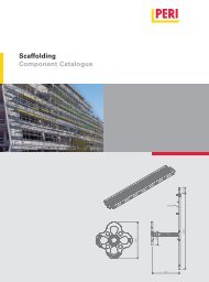
ST 100 Stacking Tower The shoring system with only one ... - Peri
ST 100 Stacking Tower The shoring system with only one ... - Peri
ST 100 Stacking Tower The shoring system with only one ... - Peri

You also want an ePaper? Increase the reach of your titles
YUMPU automatically turns print PDFs into web optimized ePapers that Google loves.
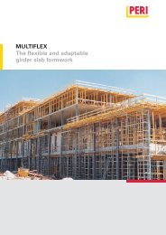
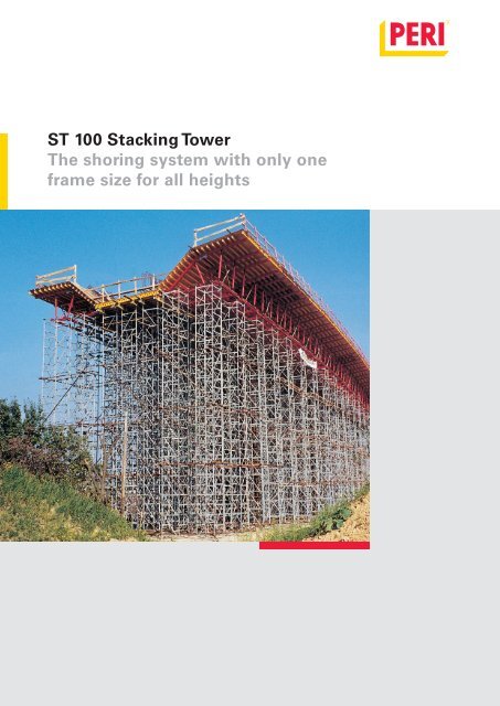
<strong>ST</strong> <strong>100</strong> <strong>Stacking</strong> <strong>Tower</strong><strong>The</strong> <strong>shoring</strong> <strong>system</strong> <strong>with</strong> <strong>only</strong> <strong>one</strong>frame size for all heights
Edition 05/2009PERI GmbHFormwork Scaffolding EngineeringP.O. Box 126489259 WeissenhornGermanyTel +49 (0)73 09.9 50- 0Fax +49 (0)73 09.9 51- 0info@peri.comwww.peri.comImportant Notes:Without exception, all current safety regulationsmust be observed in those countries where ourproducts are used.<strong>The</strong> illustrations in this brochure are photographs ofreal site situations. Safety or formwork anchordetails are therefore not to be taken as a definitiveguide to the way the equipment is to be used.Safety precautions and allowable loads are to bestrictly observed at all times. Separate structuralcalculations are required for any deviations from thestandard design data.<strong>The</strong> information contained herein is subject to technicalchanges in the interests of progress.
ContentsPERI <strong>Stacking</strong> <strong>Tower</strong> <strong>ST</strong> <strong>100</strong>2 <strong>The</strong> most suitable load tower for any site4 High load-bearing capacity even <strong>with</strong>out diagonals6 <strong>The</strong> load tower <strong>with</strong> numerous practical advantages8 Simple and fast assembly10 Small number of <strong>system</strong> comp<strong>one</strong>nts – simplecalculations12 Tables18 Comp<strong>one</strong>nts24 PERI International1
<strong>ST</strong> <strong>100</strong> <strong>Stacking</strong> <strong>Tower</strong><strong>The</strong> most suitable load tower for any site<strong>The</strong> <strong>ST</strong> <strong>100</strong> <strong>Stacking</strong> <strong>Tower</strong>, the falsework<strong>with</strong> <strong>only</strong> <strong>one</strong> frame size for allheights.With the 50 cm high stacking frame, allheights up to 22.29 m can be easily assembledand <strong>with</strong>out requiring any preplanning.No small comp<strong>one</strong>nts as the <strong>ST</strong> <strong>100</strong>does not require any connecting boltsor other parts which can easily be lostduring site operations.Detailed calculations of material accordingto combination tables, correspondingwork preparation and time-consumingsearches for many different partsare not necessary <strong>with</strong> the PERI <strong>ST</strong> <strong>100</strong>.For larger heights, the <strong>ST</strong> <strong>100</strong>is horizontally pre-assembled.<strong>The</strong> diagonal bracing ensuresthe structure is tightly connectedfor transport <strong>with</strong> thecrane.<strong>ST</strong> <strong>100</strong>, the rational and efficient <strong>shoring</strong><strong>system</strong>, can carry the heaviest ofloads, e.g. a 2.50 m thick slab at aheight of over 10 m.Regardless whether it’s high orlow – the PERI <strong>ST</strong> <strong>100</strong> is suitablefor use everywhere.2
16.10 m high <strong>shoring</strong> <strong>with</strong> PERI<strong>ST</strong> <strong>100</strong> for construction of a powerplant.3
<strong>ST</strong> <strong>100</strong> <strong>Stacking</strong> <strong>Tower</strong>High load-bearing capacity even <strong>with</strong>out diagonalsIn numerous cases, the <strong>ST</strong> <strong>100</strong> <strong>Stacking</strong><strong>Tower</strong> does not require any diagonalsbut, nevertheless, has a highload-bearing capacity (see type testand tables).<strong>The</strong> PERI <strong>ST</strong> <strong>100</strong> is type tested.This makes time-consuming static calculationsunnnecessary.This type test is available from PERI atany time.Type TestEven <strong>with</strong>out diagonals, the PERI<strong>Stacking</strong> <strong>Tower</strong> is capable of carryinglarge loads. Beams can also beformed <strong>with</strong>out any problems.Regardless whetherit is residential, industrial orbridge construction, the PERI <strong>ST</strong> <strong>100</strong> carries upto 214.0 kN per tower (take type test into consideration).4
Where slab props can no longerbe used, the <strong>ST</strong> <strong>100</strong> is quicklyassembled.With the <strong>ST</strong> <strong>100</strong>, heavy beams can beconcreted in advance. This can bed<strong>one</strong> very quickly as the <strong>ST</strong> <strong>100</strong> veryoften does not require any diagonals.<strong>The</strong> <strong>ST</strong> <strong>100</strong> Crosshead Spindlesecurely holds <strong>one</strong> or two GT 24girders so they cannot tilt.5
<strong>ST</strong> <strong>100</strong> <strong>Stacking</strong> <strong>Tower</strong><strong>The</strong> load tower <strong>with</strong> numerous practical advantages<strong>The</strong> <strong>ST</strong> <strong>100</strong> requires <strong>only</strong> 5 <strong>system</strong>parts.This means the <strong>ST</strong> <strong>100</strong> stacking towercan be erected to any height. Four comp<strong>one</strong>ntsare often sufficient if diagonalsare not required.<strong>The</strong> <strong>ST</strong> <strong>100</strong> is quickly assembled.Everything on the <strong>ST</strong> <strong>100</strong> is simply slottedtogether. Without the need of anybolts or pins.<strong>The</strong> <strong>ST</strong> <strong>100</strong> is quickly planned.<strong>The</strong> <strong>ST</strong> <strong>100</strong> has <strong>only</strong> <strong>one</strong> frame size.This means that every working height issimple to plan and organize <strong>with</strong>out theneed of combination tables.<strong>The</strong> <strong>ST</strong> <strong>100</strong> provides high levels ofsafety.With the UDI 25 x <strong>100</strong> industrial decking,safe access and working areas arecreated. Decks are quickly and easily installed.<strong>The</strong> stacking frame <strong>only</strong> weighs 7 kgwhich is used for all scaffoldingheights.<strong>The</strong> Diagonal Brace <strong>ST</strong> <strong>100</strong> has a hook at <strong>one</strong>end and the self-locking pivot at the other.This means assembly can take place veryquickly.<strong>The</strong> PERI <strong>ST</strong> <strong>100</strong> <strong>Stacking</strong> <strong>Tower</strong> issimply slotted together.6
Almost any type of main beam canbe used <strong>with</strong> the head spindle, e.g.the GT 24 girder.With large loads, the <strong>ST</strong> <strong>100</strong> HeadSpindle can also accommodate steelwalers and other steel profiles.7
<strong>ST</strong> <strong>100</strong> <strong>Stacking</strong> <strong>Tower</strong>Simple and fast assemblyAdjust the head spindles tothe required size and insert.Set up the basic frame – adjust base spindlesto required height and level accordingly.Install required number ofstacking frames.Mount head frame.8
For large heights, it can be more economicalto assemble the stacking towerin a horizontal position. In this case, alldiagonals must be used in order to ensurethat the <strong>ST</strong> <strong>100</strong> is tightly connectedenough for transport by crane.Practical tip:During horizontal assembly, the bottomdiagonals are always fixed immediatelyto the stacking frame.If the total number of the stacking frames isdivisible by 4 (i.e. 4, 8, 12, 16 etc.), the followingrule applies for the installation of the diagonals:2 tower sides arranged opposite each other =all diagonals + <strong>one</strong> diagonal in the end sections,above and below, of the 2 tower sides facingeach other.If the total number of stacking frames is notdivisible by 4 (i.e. 2, 6, 10, 14 etc.), the followingrule applies: the two sides facing each other<strong>with</strong> the same transverse spacing are fittedcompletely <strong>with</strong> diagonals.For all application variants, the following ruleapplies: whenever the tower is erected ormoved <strong>with</strong> the crane, the Safety Strap Spindleis attached at the top and bottom.9
<strong>ST</strong> <strong>100</strong> <strong>Stacking</strong> <strong>Tower</strong>Small number of <strong>system</strong> comp<strong>one</strong>nts –simple calculationsHow many comp<strong>one</strong>nts for whichtower height?With this simple calculation process,you can quickly determine how manystacking frames are required for <strong>one</strong>tower:(<strong>Tower</strong> height – 0.81 m) x 4Example:Height of tower is 5.90 m.(5.90 – 0.81) x 4 = 20.36You require 20 stacking frames.Number of base frames = always 2Number of base spindles = always 4Number of head spindles = always 4NoIs the figurein front of thepoint an evennumber?YesNumber of diagonal braces = alwaysthe same number of stacking frames -in our example, 20 pieces.<strong>The</strong> next smaller even number infront of the point is the number ofstacking frames required.<strong>The</strong> number in front of the point isthe number of stacking framesrequiredWhich spindle extension is correct?As is the case for all load-bearing scaffold,the following rule also applies tothe PERI <strong>ST</strong> <strong>100</strong>:First ensure that the base spindles arecorrectly positi<strong>one</strong>d and then begin toassemble.Example:Height of the tower is 5.90 m.5.90 – (20 stacking frames : 4) – 0.66Height of tower– (Number of stacking frames: 4)– 0.66 (2 x base frames)= remaining height (m)5.90 m = height of tower– 5.00 m = stacking frame– 0.66 m = base frame0.24 m = remaining heightNoIs the remainingheightlarger than0.40 m?Yes<strong>The</strong> remaining height is less than 0.40m. <strong>The</strong>refore, proceed as follows:Top spindle extension = 0.10 m.Bottom spindle extension0.24 m – 0.10 m = 0.14 mTop spindle extension = 0.10 mRemaining height– 0.10 m min S K= bottom spindle extensionBottom spindle extension = 0.29 mRemaining height– 0.29 m max S F= top spindle extension10
Required individual comp<strong>one</strong>nts for<strong>ST</strong> <strong>100</strong> tower heights from 1.80 upto22.29 m<strong>Tower</strong> height <strong>Stacking</strong> Diagonal Weight [kg] Weight [kg][m] min. – max. frame bracing (if required)<strong>with</strong> diagonal <strong>with</strong>out diag-bracing onal bracing1.80 – 2.29 4 4 121.50 112.382.30 – 2.79 6 6 139.70 126.022.80 – 3.29 8 8 157.90 139.663.30 – 3.79 10 10 176.10 153.303.80 – 4.29 12 12 194.30 166.944.30 – 4.79 14 14 212.50 180.584.80 – 5.29 16 16 230.70 194.225.30 – 5.79 18 18 248.90 207.865.80 – 6.29 20 20 267.10 221.506.30 – 6.79 22 22 285.30 235.146.80 – 7.29 24 24 303.50 248.787.30 – 7.79 26 26 321.70 262.427.80 – 8.29 28 28 339.90 276.068.30 – 8.79 30 30 368.008.80 – 9.29 32 32 386.209.30 – 9.79 34 34 404.409.80 – 10.29 36 36 422.6010.30 – 10.79 38 38 440.8010.80 – 11.29 40 40 459.0011.30 – 11.79 42 42 477.2011.80 – 12.29 44 44 495.4012.30 – 12.79 46 46 513.6012.80 – 13.29 48 48 531.8013.30 – 13.79 50 50 550.0013.80 – 14.29 52 52 568.2014.30 – 14.79 54 54 586.4014.80 – 15.29 56 56 604.6015.30 – 15.79 58 58 622.8015.80 – 16.29 60 60 641.0016.30 – 16.79 62 62 669.1016.80 – 17.29 64 64 687.3017.30 – 17.79 66 66 705.5017.80 – 18.29 68 68 723.7018.30 – 18.79 70 70 741.9018.80 – 19.29 72 72 760.1019.30 – 19.79 74 74 778.3019.80 – 20.29 76 76 796.5020.30 – 20.79 78 78 814.7020.80 – 21.29 80 80 832.9021.30 – 21.79 82 82 851.1021.80 – 22.29 84 84 869.30Basic comp<strong>one</strong>nts for all towerheights:2 x Base-Head Frame <strong>ST</strong> <strong>100</strong>4 x Base Spindle TR 38-70/504 x Adjustable Crosshead Spindle TR38-70/50or4 x Crosshead Spindle TR 38-70/508 x Safety Straps (if required)Complete tower heights including baseand head spindles.Weight specifications are <strong>with</strong> CrossheadSpindle TR 38-70/50.11
<strong>ST</strong> <strong>100</strong> <strong>Stacking</strong> <strong>Tower</strong>Free standing. <strong>with</strong> Adjustable Crosshead SpindleApplication Conditions (D1)– free standing– <strong>with</strong> wind– <strong>with</strong> diagonal bracing– H ≤ 5.29 mType TestNo. II B 3-543-236Perm. Leg Load60.0F V [kN]F HF VF HF VAdjustable CrossheadSpindleTR 38 – 70 / 5053.050.040.030.020.010.04.13.148.4Permissible usable resistanceμ = 0.2min. load against slidingμ = 0.442.921.817.6F H [kN]0.10 0.20 0.30 0.40 0.50 0.60Wind on the towerH ≤ 5.29 msK ≤ 340sF ≤ 300Base SpindleTR 38 – 70 / 50Application Conditions (D2)– free standing– <strong>with</strong> wind– <strong>with</strong> diagonal bracing– H ≤ 7.29 mPerm. Leg Load60.0F V [kN]F HF VF HF VAdjustable CrossheadSpindleTR 38 – 70 / 5052.650.040.030.020.010.06.65.347.7permissible usable resistanceμ = 0.2min. load against slidingμ = 0.440.930.324.5F H [kN]0.10 0.20 0.30 0.40 0.50 0.60Wind on the towerH ≤ 7.29 msK ≤ 340sF ≤ 300Base SpindleTR 38 – 70 / 5012
<strong>ST</strong> <strong>100</strong> <strong>Stacking</strong> <strong>Tower</strong>Restrained at the top, <strong>with</strong> Adjustable CrossheadSpindleApplication Conditions (D3)– restrained at the top– <strong>with</strong>/<strong>with</strong>out wind– H ≤ 5.29 m 1 diagonal brace at the topand bottom 5.29 m < H ≤ 8.29 m 2 diagonal braces atthe top and bottom 8.29 m < H ≤ 12.29 m 3 diagonal bracesat the top and bottom <strong>with</strong> horizontalcross strut at approx. H/2Perm. leg load Type TestNo. II B 3-543-236F VF V53.5 kN / leg<strong>with</strong>out wind48.5 kN / leg<strong>with</strong> windF VF VF V 53.5 kN / leg<strong>with</strong>out wind51.6 kN / leg<strong>with</strong> windF V 53.8 kN / legV<strong>with</strong>out wind52.6 kN / leg<strong>with</strong> windF V54.052.0F V [kN]53.8 53.5 53.552.6<strong>with</strong>out wind51.650.0<strong>with</strong> wind48.5H [m]48.05.0 6.0 7.0 8.0 9.0 10.0 11.0 12.0 13.05.29Application Conditions (D4)– restrained at the top– <strong>with</strong>out diagonal bracing– <strong>with</strong>/<strong>with</strong>out wind– H ≤ 8.29 m8.2912.29H ≤ 5.29 m: H 5.29 m – 8.29 m: H 8.29 m – 12.29 m:2 diagonal braces atthe top and bottom.1 diagonal brace atthe top and bottom.F VF V3 diagonal braces at thetop and bottom. Plus horizontalcross strut at H/2.Adjustable CrossheadSpindleTR 38 – 70 / 50Perm. leg loadF V [kN]52.050.850.048.0 47.746.044.05.05.29<strong>with</strong>out wind<strong>with</strong> wind48.944.1H [m]6.0 7.0 8.0 9.08.29Wind on the towerH ≤ 8.29 msK ≤ 340sF ≤ 300Base SpindleTR 38 – 70 / 5013
<strong>ST</strong> <strong>100</strong> <strong>Stacking</strong> <strong>Tower</strong>Free standing. <strong>with</strong> Crosshead SpindleApplication Conditions (D5)– free standing– <strong>with</strong> wind– <strong>with</strong> diagonal bracing– H ≤ 5.29 mType TestNo. II B 3-543-236Perm. leg loadF HF VF HF VCrosshead SpindleTR 38 – 70 / 5050.0F V [kN]43.340.030.020.010.04.42.850.043.040.030.020.010.07.05.20.10F V [kN]39.0permissible usable resistanceμ = 0.2min. load against sliding0.20 0.30 0.40 0.50 0.60permissible usable resistanceμ = 0.2μ = 0.4μ = 0.4Application Conditions (D6)– free standing– <strong>with</strong> wind– <strong>with</strong> diagonal bracing– H ≤ 7.29 mPerm. leg load38.6min. load against sliding34.823.117.5F H [kN]34.531.025.2F H [kN]Wind on the towerWind on the towerF HF VF HF VH ≤ 5.29 mH ≤ 7.29 msF ≤ 300 sK ≤ 340sF ≤ 300sK ≤ 340Base SpindleTR 38 – 70 / 50Crosshead SpindleTR 38 - 70 / 500.<strong>100</strong>.20 0.30 0.40 0.50 0.60Base SpindleTR 38 – 70 / 5014
<strong>ST</strong> <strong>100</strong> <strong>Stacking</strong> <strong>Tower</strong>Restrained at the top, <strong>with</strong> Crosshead SpindleApplication Conditions (D7)– restrained at the top– <strong>with</strong>/<strong>with</strong>out wind– H ≤ 5.29 m 1 diagonal brace at the topand bottom 5.29 m < H ≤ 8.29 m 2 diagonal braces atthe top and bottom 8.29 m < H ≤ 12.29 m 3 diagonal bracesat the top and bottom <strong>with</strong> additionalcross strut at approx. H/2Perm. leg loadType TestNo. II B 3-543-236F VF VF V 43.7 kN / leg<strong>with</strong>out wind41.5 kN / leg<strong>with</strong> windF V 44.3 kN / leg<strong>with</strong>out wind42.7 kN / leg<strong>with</strong> windF VF V43.3 kN / leg<strong>with</strong>out wind39.1 kN / leg<strong>with</strong> windF V46.0F V [kN]44.044.342.743.7<strong>with</strong>out wind43.342.041.540.0<strong>with</strong> wind39.138.0H [m]5.0 6.0 7.0 8.0 9.0 10.0 11.0 12.0 13.01 diagonal brace atthe top and bottom.5.29Application Conditions (D8)– restrained at the top– <strong>with</strong>out diagonal bracing– <strong>with</strong>/<strong>with</strong>out wind– H ≤ 8.29 m8.2912.29H ≤ 5.29 m: H 5.29 m – 8.29 m: H 8.29 m – 12.29 m:2 diagonal braces atthe top and bottom.F VF V3 diagonal braces at thetop and bottom. Additionalhorizontal cross strut atH/2.Crosshead SpindleTR 38 – 70 / 50Perm. leg loadF V [kN]46.0sK ≤ 34044.042.040.038.05.044.342.7 42.85.29<strong>with</strong>out wind<strong>with</strong> wind6.0 7.0 8.039.08.29H [m]Wind on the towerH ≤ 8.29 msF ≤ 300Base SpindleTR 38 – 70 / 5015
<strong>ST</strong> <strong>100</strong> <strong>Stacking</strong> <strong>Tower</strong>Restrained at the top, 12.29 m ≥ H ≤ 22.29 m,<strong>with</strong> Adjustable Crosshead SpindleSupplement for (D3)– restrained at the top– <strong>with</strong>/<strong>with</strong>out wind– <strong>with</strong> diagonal bracing all around– 2 horizontal cross struts at every H/3Perm. leg loadF V [kN]55.053.550.048.545.0<strong>with</strong>out wind52.8<strong>with</strong> wind40.037.935.012.012.2913.0 14.0 15.0 16.0 17.0 18.0 19.0 20.0 21.0 22.0 23.022.29H [m]F VF VAdjustable CrossheadSpindleTR 38 – 70 / 50sF ≤ 300Wind on the towerH = 12.29 - 22.29 msK ≤ 340Base SpindleTR 38 – 70 / 5016
<strong>ST</strong> <strong>100</strong> <strong>Stacking</strong> <strong>Tower</strong>Restrained at the top, 12.29 m ≥ H ≤ 22.29 m,<strong>with</strong> Adjustable Crosshead SpindleSupplement for (D7)– restrained at the top– <strong>with</strong>/<strong>with</strong>out wind– <strong>with</strong> diagonal bracing all around– 2 horizontal cross struts at every H/3Perm. leg load50.0F V [kN]45.043.3<strong>with</strong>out wind43.340.039.1<strong>with</strong> wind35.034.830.012.012.2913.0 14.0 15.0 16.0 17.0 18.0 19.0 20.0 21.0 22.0 23.022.29H [m]F VF VsF ≤ 300sK ≤ 340Crosshead SpindleTR 38 – 70 / 50Wind on the towerH =12.29 - 22.29 mBase SpindleTR 38 – 70 / 5017
<strong>ST</strong> <strong>100</strong> <strong>Stacking</strong> <strong>Tower</strong>Item no. Weight kg019900 16,600 Base-Head Frame <strong>ST</strong> <strong>100</strong>, galv.Base and head frame for <strong>ST</strong> <strong>100</strong> <strong>Stacking</strong> <strong>Tower</strong>.450Ø48,3Ø2233080125 125<strong>100</strong>0<strong>100</strong>0019910 6,820 <strong>Stacking</strong> Frame <strong>ST</strong> <strong>100</strong>, galv.<strong>Stacking</strong> Frame for <strong>ST</strong> <strong>100</strong>. 4 required per metre rise.Ø48,3250500738250Ø22125<strong>100</strong>0125019940 2,290 Diagonal Brace <strong>ST</strong> <strong>100</strong>, galv.Diagonal for <strong>Stacking</strong> <strong>Tower</strong> <strong>ST</strong> <strong>100</strong>. <strong>The</strong> numberrequired depends on the static <strong>system</strong>.1300Ø34125018
<strong>ST</strong> <strong>100</strong> <strong>Stacking</strong> <strong>Tower</strong>Item no. Weight kg019780 5,160 Base Spindle TR 38-70/50For more heavily loaded <strong>shoring</strong>.NoteWith captive swivel nut.38140110535min 47 max71080Ø19Ø21Ø10Ø14019950 7,690 Crosshead Spindle Tr 38-70/50Head spindle for providing stable support for singleor twin GT 24 girders.NoteWith captive swivel nut.Ø6,5195535min 47 max7102401703885155028590 0,568AccessoriesTension Strap, 16-25, galv.019790 6,360 Adjustable Crosshead Spindle TR 38-70/50Maximum tilt of the head plate = 4.4 % in anydirection.NoteWith captive swivel nut.From 01.07.2009, available<strong>only</strong> as rentable item.170 37,5 85 37,5535min 51 max717 50Ø1319011080Ø19Ø1438160Ø10Ø2119
<strong>ST</strong> <strong>100</strong> <strong>Stacking</strong> <strong>Tower</strong>Item no. Weight kg116081 6,950 Adjustable Crosshead Spindle TR 38-70/50Maximum tilt of the head plate = 4.4 % in anydirection.NoteWith locking device and captive swivel nut.170 37,5 85 37,5min 60 max 535687 80Ø102408076Ø19Ø14160Ø38Ø<strong>100</strong>285900183000,5680,564AccessoriesTension Strap, 16-25, galv.Cross Strap, galv.028590 0,568 Tension Strap, 16-25, galv.For assembling 2 x GT 24 Girders or VT 20 ontoCrosshead and Adjustable Crosshead Spindle TR 38.NoteSpanner size SW 19.210270SW 191<strong>100</strong>18300 0,564 Cross Strap, galv.For mounting of Steel Waler SRZ and SRU ontoAdjustable Crosshead Spindle TR 38.Ø2050150<strong>100</strong>18350 0,310AccessoriesHex. Bolt 4016 M16 x 160-4.6 MU, galv.20
<strong>ST</strong> <strong>100</strong> <strong>Stacking</strong> <strong>Tower</strong>Item no. Weight kg019800 0,063 Safety Strap Spindle <strong>ST</strong> <strong>100</strong>For preventing the spindles from falling out whenbeing moved by crane.Ø71154019920 6,180 End Waler <strong>ST</strong> <strong>100</strong>, galv.For bracing the End Frames <strong>ST</strong> <strong>100</strong>. 2 pieces perwaler line.62208<strong>100</strong>090019930 5,260 End Frame <strong>ST</strong> <strong>100</strong>, galv.As alternative for the Base Frame <strong>ST</strong> <strong>100</strong>. In combination<strong>with</strong> the End Waler <strong>ST</strong> <strong>100</strong>. 2 pieces perwaler line.80330250Ø22Ø48,3450125 125<strong>100</strong>0019810 1,010 Connector <strong>ST</strong> <strong>100</strong>, galv.For connecting the <strong>ST</strong> <strong>100</strong> <strong>with</strong> additional frames.Required where heavy point loads are to be supported.2per additional frame and metre rise.250 30Ø1011230721
<strong>ST</strong> <strong>100</strong> <strong>Stacking</strong> <strong>Tower</strong>Item no. Weight kg106092 6,960 Industrial Deck UDI 25 x <strong>100</strong>To be used on Ledgers UH.X perm. p [kN/m²]<strong>100</strong>0 10.0<strong>100</strong>06096245065050 124,000 Pallet <strong>ST</strong> <strong>100</strong>-2, galv.For stacking and transportation of <strong>ST</strong> <strong>100</strong> <strong>Stacking</strong><strong>Tower</strong> comp<strong>one</strong>nts. Capacity: 84 <strong>Stacking</strong> Frames+ Base- and Head Spindles + Diagonal Braces.Safety instructionsLoad-carrying capacity 1.0 t.Follow Instruction for Use!300 4007009702280240090010200264150264170264110264120264130264140264190264183,5500,0003,5507,<strong>100</strong>10,65014,20017,75021,600Scaffold Tube Steel Ø 48.3 x 3.2Scaffold Tube Steel Ø 48.3 x 3.2, Special LengthCutting Costs for Scaffold TubesScaffold Tube Steel Ø 48.3 x 3.2, l = 1.0 mScaffold Tube Steel Ø 48.3 x 3.2, l = 2.0 mScaffold Tube Steel Ø 48.3 x 3.2, l = 3.0 mScaffold Tube Steel Ø 48.3 x 3.2, l = 4.0 mScaffold Tube Steel Ø 48.3 x 3.2, l = 5.0 mScaffold Tube Steel Ø 48.3 x 3.2, l = 6.0 mL<strong>100</strong>020003000400050006000LØ48,3x3,222
<strong>ST</strong> <strong>100</strong> <strong>Stacking</strong> <strong>Tower</strong>Item no. Weight kg017020 1,120 Standard Coupling NK 48/48, galv.For scaffold tubes Ø 48 mm.NoteSpanner size SW 19.( 9 )SW 19017010 1,400 Swivel Coupling DK 48/48, galv.For scaffold tubes Ø 48 mm.NoteSpanner size SW 19.(27)SW 1923
PERI International422019223201 PERI GmbHRudolf-Diesel-Strasse89264 Weissenhorninfo@peri.comwww.peri.com2441125639118171629532130134834382841524661331202 FrancePERI S.A.S.77109 Meaux Cedexperi.sas@peri.frwww.peri.fr09 ItalyPERI S.p.A.20060 Basiano (MI)info@peri.itwww.peri.it16 AustriaPERI Ges.mbH3134 Nußdorf ob der Traisenoffice@peri.atwww.peri.at23 KoreaPERI (Korea) Ltd.Seoul 135-080info@perikorea.comwww.perikorea.com29 SlovaniaPERI SLOWENIEN2000 Mariborperi.slo@triera.netwww.peri.de03 SwitzerlandPERI AG8472 Ohringeninfo@peri.chwww.peri.ch04 SpainPERI S.A. SociedadUnipersonal28110 Algete/Madridinfo@peri.eswww.peri.es05 Belgium/LuxembourgN.V. PERI S.A.1840 Londerzeelinfo@peri.bewww.peri.be06 NetherlandsPERI B.V.5480 AH-Schijndelinfo@peri.nlwww.peri.nl10 JapanPERI Japan K.K.Tokyo 103-0015info@perijapan.jpwww.perijapan.jp11 United Kingdom/IrelandPERI Ltd.Rugby, CV23 0ANinfo@peri.ltd.ukwww.peri.ltd.uk12 TurkeyPERI Kalıp ve İskeleleriKıraç - Büyükçekmece/Istanbul 34500info@peri.com.trwww.peri.com.tr13 HungaryPERI Kft..1181 Budapestinfo@peri.huwww.peri.hu07 USA14 MalaysiaPERI Formwork Systems, Inc. PERI Formwork MalaysiaElkridge, MD 2107543300 Seri Kembangan,info@peri-usa.comSelangor DEwww.peri-usa.cominfo@perimalaysia.comwww.perimalaysia.com08 Ind<strong>one</strong>siaPT Beton Perkasa Wijaksana 15 SingaporeJakarta 10210PERI ASIA Pte. Ltdbpw@betonperkasa.com Singapore 387355www.peri.depha@periasia.comwww.periasia.com17 Czech RepublicPERI spol. s r.o.252 42 Jeseniceinfo@peri.czwww.peri.cz18 DenmarkPERI Danmark A/S2670 Greveperi@peri.dkwww.peri.dk19 FinlandPERI Suomi Ltd. Oy05460 Hyvinkääinfo@perisuomi.fiwww.perisuomi.fi20 NorwayPERI NORGE AS3036 Drammeninfo@peri.nowww.peri.no21 PolandPERI Polska Sp. z o.o.05-860 Płochocininfo@peri.pl.plwww.peri.pl.pl22 SwedenPERIform SVERIGE AB30013 Halmstadperi@periform.sewww.periform.se24 PortugalPERIcofragens Lda.Linda-a-Pastora2790-326 Queijasinfo@peri.ptwww.peri.pt25 ArgentinaPERI S.A.(1625) Escobar/Prov. Bs. As.info@peri.com.arwww.peri.com.ar26 BrazilPERI Formas eEscoramentos Ltda.CEP 06730-000Vargem Grande PaulistaSão Pauloinfo@peribrasil.com.brwww.peribrasil.com.br27 ChilePERI Chile Ltda.Colina, Santiago de Chileperich@peri.clwww.peri.cl28 RomaniaPERI România SRL077015 Baloteşti - ILFOVinfo@peri.rowww.peri.ro30 SlovakiaPERI spol. s r.o.903 01 Senecinfo@peri.skwww.peri.sk31 AustraliaPERI Australia Pty. Ltd.Glendenning NSW 2761info@periaus.com.auwww.periaus.com.au32 EstoniaPERI AS76401 Saku valdHarjumaaperi@peri.eewww.peri.ee33 GreecePERI Hellas Ltd.194 00 Koropiinfo@perihellas.grwww.perihellas.gr34 LatviaPERI SIA1057 Rigainfo@peri-latvija.lvwww.peri-latvija.lv35 United Arab EmiratesPERI (L.L.C.)Dubaiperillc@perime.comwww.perime.com24
364443750 512310493739 40545760 5647 5958 3555631415862262725453136 CanadaPERI Formwork Systems, Inc.Bolton, OntarioL7E 1K1info@peri.cawww.peri.ca37 LibanonPERI GmbHBeirutP.O. Box 90 416 Jdeidetlebanon@peri.dewww.peri.de38 LithuaniaPERI UAB02300 Vilniusinfo@peri.ltwww.peri.lt39 MaroccoPERI S.A.Tangerperi25@menara.mawww.peri.de40 IsraelPERI FormworkEngineering Ltd49002 Israelinfo@peri.co.ilwww.peri.co.il41 BulgariaPERI BULGARIA EOOD1839 – Sofiaperi.bulgaria@peri.bgwww.peri.bg42 IcelandME<strong>ST</strong> ltd.,220 Hafnarfjordurmest@mest.iswww.mest.is43 KazakhstanTOO PERI Kazakhstan050010 Almatyperi@peri.kzwww.peri.kz44 Russian FederationOOO PERI142403 Noginskmoscow@peri.ruwww.peri.ru45 South AfricaPERI Wiehahn (Pty.) Ltd.Bellville 7535ask@wiehahn.co.zawww.periwiehahn.co.za46 UkraineTOW PERI Ukraina02002 Kiewperi@peri.uawww.peri.ua47 EgyptPERI GmbH11361 HeliopolisCairoinfo@peri.com.egwww.peri.com.eg48 SerbiaPERI Oplate d.o.o.11070 Novi Beogradoffice@peri.co.yuwww.peri.co.yu49 MexicoPERI Cimbras y Andamios,S.A. de C.V.Estado de México,C.P. 54680info@peri.com.mxwww.peri.com.mx50 AzerbaijanPERI Kalıp ve İskeleleriBakuperibaku@peri.com.trwww.peri.com.tr51 TurkmenistanPERI Kalıp ve İskeleleri744035 Aşgabatperiashgabat@peri.com.trwww.peri.com.tr52 BelorussiaPERI Belarus220030 Minskperi@mail.belpak.bywww.peri.com.tr53 CroatiaPERI oplate i skele d.o.o.10 250 Donji Stupnik/Zagrebinfo@peri.com.hrwww.peri.com.hr54 IranPERI GmbHBuilding No. 4P.O. Box 1939793669Teheran-Iraniran@peri.irwww.peri.ir55 IndiaPERI (India) Pvt LtdMumbai – 400064info@peri.inwww.peri.in56 JordanPERI Jordan11947 Ammanjordan@peri.dewww.peri.de57 KuwaitPERI Kuwait13011 Kuwaitkuwait@peri.dewww.peri.de58 Saudi ArabiaPERI Saudi ArabiaJeddah - 21463K.S.Asaudi-arabia@peri.dewww.peri.de59 QatarPERI Qatar LLCDohaqatar@peri.dewww.peri.de60 AlgeriaSociété PERI S.A.S.Kouba - Algerperi.alger@peri.frwww.peri.fr61 AlbaniaAutostrada TIRANE-DURRE<strong>ST</strong>irane / ALBANIAinfo@peri.com.trwww.peri.com.tr62 PeruPERI Peruana SACLima/Perujeanpierre.saux@peri.com.pe63 PanamaPERI Panama Inc.587 Panama Cityjohny.fernandezc@gmail.comwww.peri.com25
PERI Product RangeWall FormworkPanel FormworkGirder FormworkCircular FormworkFacade FormworkBrace FrameClimbing SystemsClimbing ScaffoldSelf-Climbing SystemClimbing Protection PanelPlatform SystemsColumn FormworkSquareRectangularCircularScaffold, Stairways,Working PlatformsFacade ScaffoldWorking PlatformWeather Protection RoofStairway AccessSlab FormworkPanel FormworkBeam Grid FormworkGirder FormworkSlab TableBeam FormworkBridge and TunnelFormworkCantilevered Parapet CarriageCantilevered Parapet PlatformEngineer’s Construction KitShoring SystemsSteel Slab PropsAluminium Slab Props<strong>Tower</strong> SystemsHeavy-Duty PropsServicesFormwork AssemblyCleaning / RepairsFormwork PlanningSoftwareStaticsSpecial ConstructionsAdditional SystemsPlywoodFormwork GirdersStopend SystemsPalletsTransportation ContainersD e 12/2010 5ma Art.-Nr.: 790122 © Copyright by PERI GmbHPERI GmbHFormwork Scaffolding EngineeringP.O. Box 126489259 WeissenhornGermanyTel +49 (0)73 09.9 50- 0Fax +49 (0)73 09.9 51- 0info@peri.comwww.peri.com