Create successful ePaper yourself
Turn your PDF publications into a flip-book with our unique Google optimized e-Paper software.
<strong>CB</strong> <strong>240</strong><strong>Climbing</strong> <strong>Scaffold</strong>Assembly Instructions for Standard ConfigurationEdition 02/2011
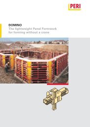
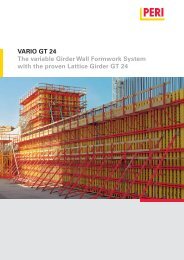
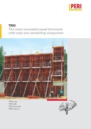
<strong>CB</strong> <strong>240</strong> <strong>Climbing</strong> <strong>Scaffold</strong>ContentsIntroductionOverview, Main Components 1Standard Configuration 4Intended Use 4Safety Instructions 5General 5Load Models 6Standard work flow 8A1 Assembly of the <strong>CB</strong> <strong>240</strong> PlatformRequired resources 10Assembly of <strong>CB</strong> <strong>240</strong> brackets 11Girder assembly 12<strong>CB</strong> <strong>240</strong> carriage assembly 14Assembly of decking for working platform 16Guardrail assembly 18A2 Other assembly workAssembly of end guardrails 20Assembly of hinged hatch cover 21Assembly of finishing platform 22Finishing tasks 23B1 Work on the construction siteAnchoring 24Mounting of <strong>CB</strong> <strong>240</strong> climbing platform 30Mounting of <strong>CB</strong> <strong>240</strong> finishing platform 32Assembly of wind bracing 35Removal of climbing cones 37Dismantling of climbing scaffold 37Ladder assembly 38B3 Formwork Utilisation<strong>CB</strong> carriage Operations 48Formwork Alignment 49Adjusting the inclination 50Horizontal adjustment – VARIO 50B4 Moving the unitsPreparation 51Securing the units 52Moving procedure 53C1 Planning and Work PreparationStatic system 54Platform dimensioning 55Anchoring verification 55Platform decking 56Handrails and guardrails 59Connecting VARIO GT 24 formwork 60Connecting TRIO formwork 62Moving the units 64Ladder Access 65Drawings and plans 65Use on circular structures 66Corner platforms 66ComponentsComponents 68B2 Assembly of formwork elementsVARIO GT 24 Element 40TRIO Element 44KeySafety Instructions Note Visual Check TipAssembly Instructions for Standard Configuration
<strong>CB</strong> <strong>240</strong> <strong>Climbing</strong> <strong>Scaffold</strong>IntroductionOverview, Main ComponentsConcreting platform<strong>Climbing</strong> <strong>Scaffold</strong> <strong>CB</strong> <strong>240</strong> with TRIOPanel Formwork– concreting height 3.60 m– extended suspension of finishingplatform– Tension Belt <strong>CB</strong> as wind bracing*Formwork height = concreting height+ formwork projection (max. 5.40 m)Formwork height hs51043Working platform2 1111 Working platform with <strong>Climbing</strong> Bracket <strong>CB</strong> <strong>240</strong>2 Carriage <strong>CB</strong> <strong>240</strong> with Rack <strong>CB</strong> <strong>240</strong>3 Adjustable Brace <strong>CB</strong> 164-2244 Strongback <strong>CB</strong> 270 or <strong>CB</strong> 3805 Anchoring and Leading Anchor6 Bracing Shoe Wall <strong>CB</strong> M247 Wind bracing with tension belt or tie rod8 Finishing Platform with Platform Beam <strong>CB</strong>9 Suspension of finishing platform10 VARIO GT 24 or TRIO formwork with concreting scaffold11 Bracing with scaffold tubesConcreting height679Finishing platform82 Assembly Instructions for Standard Configuration
<strong>CB</strong> <strong>240</strong> <strong>Climbing</strong> <strong>Scaffold</strong>IntroductionOverview, Main ComponentsAnchoring to the building structureVersion 15.4 Threaded Anchor Plate DW 15*5.5 Tie Rod DW 15*, Z-12.4-70L 1 = h – 8 cmor Tie Rod B15*, Z-12.5-825.3 <strong>Climbing</strong> Cone 2 M24/DW 155.6 <strong>Scaffold</strong> Mounting Ring M24, galv.5.7 Hex. Bolt M24 x 120 ISO 4014 - 10.95.8 Spacer Tube DR 22* (optional)L 2 = h – 18,5 cm(tolerance 0 to +5 mm)Anchoring depth h = variable,min 185 mm.Ø 8L 1h5.4 5.5 5.3 5.6 5.7* “Lost components”With PVC spacer tube, the tie rod (5.5)is reusable.L 25.8Version 25.2 Threaded Anchor Plate DW 20*5.1 Screw-On Cone 2 M24/DW 205.6 <strong>Scaffold</strong> Mounting Ring M24, galv.5.7 Hex. Bolt M24 x 120 ISO 4014 - 10.9Anchoring depth h = 15.5 cm* “Lost component”Ø 1015,55.2 5.1 5.6 5.7Assembly Instructions for Standard Configuration3
<strong>CB</strong> <strong>240</strong> <strong>Climbing</strong> <strong>Scaffold</strong>IntroductionStandard ConfigurationGeneralThe <strong>CB</strong> <strong>240</strong> climbing scaffold system isnormally used as shoring in order tosupport anchored wall formwork in accordancewith EN 12812. The formworkis firmly connected with the scaffoldingand is moved as a single unit suspendedon a crane. It can also be used as workingscaffold only. The working platformfor operating the formwork consists ofplanking, platform beams and two fixedclimbing brackets. These transfer theloads deriving from the dead weight,live loads and prevailing wind loads viathe anchorage and bottom pressurepoint into the structure.The working platform can be supplementedwith:– formwork carriage, strongback andadjustable brace for accommodatingthe VARIO and TRIO formwork systems.– a height-adjustable finishing platformcomplete with access ladder which isattached to posts.– end-to-end guardrails on the workingand finishing platforms in accordancewith EN 12811.– a tension anchor which preventstipping inwards.Technical Data:– width of bracket: 2.40 m– static height: 1.80 m– retraction length: 75 cm– max. formwork height: 5.40 mIntended Use1. PERI products have been exclusivelydesigned as technical work equipmentfor use in the industrial and commercialsectors by suitably trained personnel.2. These assembly instructions serve asthe basis for the project-related riskassessment and the instructions for theprovision and use of the system by thecontractor (user). However, they do notreplace these.3. Only PERI original components maybe used. The use of other products andspare parts represents a misapplicationwith associated safety risks.4. The components are to be inspectedbefore each use to ensure that theyare in perfect condition and functioncorrectly.5. Changes to PERI components arenot permitted and represent a misapplicationwith associated safety risks.6. Safety instructions and permissibleloads must be observed at all times.7. Components provided by the contractormust conform with the characteristicsrequired in these assembly instructionsas well as all valid constructionguidelines and standards.In particular, the following apply ifnothing else is specified:– timber components: Strength ClassC24 for Solid Wood EN 338.– scaffold tubes: galvanised steeltubing with minimum dimensionsØ 48.3 x 3.2 mm according toEN 12811-1:2003 4.2.1.2.– scaffold tube couplings accordingto EN 74.8. Deviations from the standard configurationmay only be carried out aftera separate risk assessment has beencompleted by the contractor (user).On this basis, appropriate measuresfor the working safety and stability areto be implemented.4 Assembly Instructions for Standard Configuration
<strong>CB</strong> <strong>240</strong> <strong>Climbing</strong> <strong>Scaffold</strong>IntroductionSafety InstructionsGeneral1. Deviations from the standard configurationand/or intended use presenta potential safety risk.2. All country-specific laws, standardsand other safety regulations are tobe taken into account whenever ourproducts are used.3. During unfavourable weather conditions,suitable precautions and measuresare to be taken in order to ensureboth working safety and stability.4. The contractor (user) must ensurethe stability throughout all phases ofconstruction. He must ensure andverify that all loads which occur aresafely transferred.5. The contractor (user) has to providesafe working areas for site personnelwhich are to be reached through theprovision of safe access ways. Areas ofrisk must be cordoned off and clearlymarked. Hatches and openings onaccessible working areas must be keptclosed during working operations.6. For better comprehensibility, detaileddrawings are partly incomplete. Thesafety installations which have possiblynot been featured in these detaileddrawings must nevertheless be available.Storage and Transportation1. Do not drop the components.2. Store and transport components ensuringthat no unintentional change intheir position is possible. Detach liftinggear from the lowered units only ifthese are in a stable position and nounintentional change is possible.3. When moving the components, makesure they are lifted and set down sothat any unintentional tilting over, fallingapart, sliding or rolling away are avoided.4. Use only suitable load-carrying equipmentto move the components as wellas the designated load-bearing points.5. During the lifting and movingprocedure, ensure all loose parts areremoved or secured.6. During the moving procedure, alwaysuse a guide rope.7. Move components on clean, flat andsufficiently load-bearing surfaces only.System-specific1. Retract components only when theconcrete has sufficiently hardened andthe person in charge has given thego-ahead for striking to take place.2. Anchoring is to take place only if theanchorage has sufficient concretestrength.3. It is the responsibility of the contractor(user) to inspect all anchors andassociated components.4. Enclosure of the platform or mountingof additional surfaces which areexposed to the influences of the windchanges the stability and must thereforebe checked. If necessary, additionalmeasures must be implemented.5. The platforms are to be inspectedfor signs of damage by authorisedpersonnel at regular intervals. Dirtwhich affects the functionality is tobe removed immediately.6. As a result of the moving procedure,falling edges are formed between theplatforms. Corresponding areas are tobe secured.7. Site personnel, construction materialsor tools may not be transportedwhile the scaffold unit is being movedwith the crane. Exceptions to this canbe determined through the operationalworking and assembly instructions.GeneralAdditional PERI product information– <strong>CB</strong> <strong>240</strong> climbing scaffold type test– “PERI <strong>CB</strong> <strong>240</strong> and <strong>CB</strong> 160 <strong>Climbing</strong><strong>Scaffold</strong>” brochure– Instructions of Use for the CraneSplice 24– Instructions for Use for the TRIOLifting Hook– PERI Design Tables for FormworkTechnologyThe assemblies shown in these PERIassembly instructions are only exampleswhich feature only one componentsize. They are accordingly valid for allcomponent sizes contained in thestandard configuration.Assembly Instructions for Standard Configuration5
<strong>CB</strong> <strong>240</strong> <strong>Climbing</strong> <strong>Scaffold</strong>IntroductionLoad ModelsWorking positionThe area-related live loads correspondto EN 12811.Concreting platform150 kg/m²,Load Class 2Working platform200 kg/m²,Load Class 3300 kg/m 2Finishing platform75 kg/m²,Load Class 16 Assembly Instructions for Standard Configuration
<strong>CB</strong> <strong>240</strong> <strong>Climbing</strong> <strong>Scaffold</strong>IntroductionLoad ModelsConcreting postitionThe area-related live loads correspondto EN 12811.Concreting platform150 kg/m²,Load Class 2Working platform200 kg/m²,Load Class 3Finishing platform75 kg/m²,Load Class 1Assembly Instructions for Standard Configuration7
<strong>CB</strong> <strong>240</strong> <strong>Climbing</strong> <strong>Scaffold</strong>IntroductionStandard work flowPreparation1. Assemble wall formwork.2. Assemble platform.3. Assemble finishing platform.Initial use1. Position wall formwork for first wallsection.2. Add reinforcement to first wall section.3. Mount leading anchor and closeformwork.4. Place formwork anchor.5. Pour first wall section.6. Remove advancing bolts and strike.7. Mount scaffold mounting rings.8. Attach climbing platforms.9. Assemble tension anchor ifnecessary.10. Place formwork on climbing platformand secure.11. Clean formwork and adjust ifnecessary.12. Reinforce second wall section.13. Mount leading anchor and closeformwork.14. Place formwork anchor.15. Pour second wall section.16. Remove advancing bolts and retractformwork.17. Mount scaffold mounting rings.8 Assembly Instructions for Standard Configuration
<strong>CB</strong> <strong>240</strong> <strong>Climbing</strong> <strong>Scaffold</strong>Introduction18. Attach finishing platform.19. Move climbing scaffold to secondwall section.20. Bolt on finishing platform and attachguardrails.21. If necessary, mount ladder.Standard cycle22. Mount tension anchor if required.23. Clean formwork and adjust.24. Install reinforcement to wall.25. Mount leading anchor and closeformwork.26. Place formwork anchor.27. Pour wall section.28. Remove advancing bolts and retractformwork.29. Mount scaffold mounting rings.30. Remove climbing cones fromprevious wall section.31. Move climbing scaffold to next wallsection.Continue with standard cycle.32. Dismantle climbing scaffold.Assembly Instructions for Standard Configuration9
<strong>CB</strong> <strong>240</strong> <strong>Climbing</strong> <strong>Scaffold</strong>A1 Assembly of the <strong>CB</strong> <strong>240</strong> PlatformRequired resourcesEquipment and toolsHammer, Wire Pins, Plumb Line,4 Screw Clamps with 300 mm clampinglength, Circular Saw, Electric Drill,HSS Drill Ø 6 mm, Ø 8 mm,min. L = 180 mm072180 Ratchet Wrench SW 24 – 1/2”102784 Socket SW 24 – 1/2”029620 Socket SW 19 – 1/2”072170 Socket SW 13 – 1/2”072150 Power Wrench M14, ASB 636072210 Power Screwdriver SCU 7-9072220 Bit Holder072230 Magnetic Holder072140 Bit Point TX 30031480 Socket Wrench SW 36027212 Allen Key SW 14031080 Drill Bit Ø 25 mm3,5 m82 mm 82 mmAca. 50 cmCentre lineof bracket0.10.12 stop barsSupport0.2Centre lineof bracket0.362 mm A62 mmC2,0 m1,0 mFig. A1.01Flat assembly surfaceWidth: approx. 3.50 mLength: maximum platform width +min. 2.0 mAttach stop bars and support.(Fig. A1.01)Aids– Locating Block (0.1) 12 plywoodblocks 21 x 80 x 80 mm– Support (0.2) h = approx. 24 cm, e.g.GT 24, L = max. bracket spacing + 1.0 m– Stop Bars (0.3) 1 plank 40 x 120 mm1 plank 80 x 80 mm, L = max. bracketspacing + 1.0 m– Gauge for bracket spacing (0.4)1 plank 40 x 120 mm, L = bracketspacing + max. 1.0 m Formliningblocks (4) (Fig. A1.02)– Diagonal bracing for securing bracket(0.5) 1 plank 40 x 120 mm, L = 2.0 m(Fig. A1.03)Section A-AWall sideGuardrail side120 mm 83 mm 2,398 m 80 mm0.20.1 0.482 mm 82 mmC Fig. A1.020.5<strong>240</strong>Fig. A1.01aAre the stop bars and support mountedin parallel?0.2Fig. A1.0310Assembly Instructions for Standard Configuration
<strong>CB</strong> <strong>240</strong> <strong>Climbing</strong> <strong>Scaffold</strong>A1 Assembly of the <strong>CB</strong> <strong>240</strong> PlatformAssembly of <strong>CB</strong> <strong>240</strong> bracketsAssembly1. Check centre-to-centre spacing ofbrackets conforms to planning details,or measure spacing of climbing conesalready cast in concrete.2. Adjust centre-to-centre spacing ofbrackets to the support (0.2).(Fig. A1.04)0.2Fig. A1.04The bracket axis forms a right-angle tothe stops and support.3. Fix locating blocks (0.1).(Fig. A1.05)For spacings: see Fig. A1.02.0.14. Vertically lift first bracket (1.1) intothe stops and then align.Fig. A1.055. Fix together with the diagonalbracing (0.5). (Fig. A1.06)0.51.1Fig. A1.066. Lift in second bracket and align usingbracket spacing gauge. Fix gauge usingscrew clamps. Check bracket spacing.(Fig. A1.07)Fig. A1.077. Fix two scaffold tubes (11.1) to screwcouplings (1.3) in a parallel position toprovide support.8. Brace with diagonal scaffold tube(11.2) and two swivel couplings (11.3).(Fig. A1.08)11.211.311.1The brackets are now aligned.1.3Fig. A1.08Assembly Instructions for Standard Configuration11
<strong>CB</strong> <strong>240</strong> <strong>Climbing</strong> <strong>Scaffold</strong>A1 Assembly of the <strong>CB</strong> <strong>240</strong> PlatformAssembly of platformbeamsWhen using PERI GT 24 girders,strengthen these on both sides inthe area of the brackets with plywoodstrips (13.2).(Fig. A1.09)Dimensions: thickness/width/height27 x 120 x 300 mmFixing: Torx TSS 6 x 6013.213.1Assembly1. Fix girder (13.1) by means of screwclamps. (Fig. A1.10).2. Fix diagonals to the fixing plate usingtwo hex. wood screws 6 x 80 DIN 571(13.3).(Fig. A1.11)Alternatively:Round head bolts M6 x 100 DIN 603and washer, or M6 x 180 (13.4) fordouble girders.13.113.2Fig. A1.09Pre-drill girders when using round headbolts.Use round head bolts for longer girdercantilevers.Timbers must be fixed accordingly.The girders are now assembled.Fig. A1.1013.3Fig. A1.1112 Assembly Instructions for Standard Configuration
<strong>CB</strong> <strong>240</strong> <strong>Climbing</strong> <strong>Scaffold</strong>A1 Assembly of the <strong>CB</strong> <strong>240</strong> PlatformSingle girder position– plywood or 3-ply board (13.2)– hex. wood screw 6 x 80 DIN 571(13.3)– timber 8/16 (13.6)– GT 24 lattice girder (13.7)(Fig. A1.12 + A1.13)GT 24 girder13.313.213.7Timber13.313.6Fig. A1.12 Fig. A1.13Double girder position– plywood or 3-ply board (13.2)– timber 8/16 (2x) or 16 x 16 (1x) (13.6)– round head bolt M6 x 180 DIN 603(13.4)– GT 24 lattice girder (13.7)(Fig. A1.14 + A1.15)13.413.213.213.613.4These drawings conform to AppendixK15 of the type test issued by the StateStructural Inspectorate, Düsseldorf, andmay only be used in accordance withthe aforementioned type test.Fig. A1.14 Fig. A1.15Assembly Instructions for Standard Configuration13
<strong>CB</strong> <strong>240</strong> <strong>Climbing</strong> <strong>Scaffold</strong>A1 Assembly of the <strong>CB</strong> <strong>240</strong> PlatformAssembly of <strong>CB</strong> <strong>240</strong> CarriageAssembly1. Retract the wedge (2.2).2. Insert rack 2.7 into the carriage (2.1).(Fig. A1.16)3. Secure with wedge (2.2). (Fig. A1.17)4. Remove lower-positioned bolts (2.4)and roller (2.3) from the carriage.(Fig. A1.16)2.9Fig. A1.162.12.82.42.22.52.22.32.72.32.4Fig. A1.172.6(2.1) Carriage <strong>CB</strong> <strong>240</strong>(2.2) Wedge(2.3) Rollers Ø 60 x 85(2.4) Bolt Ø 25 x 180 with Cotter Pin 4/1(2.5) Traction Screw SW 19(2.6) Bolt Ø 16 x 65/86 with Cotter Pin 4/1(2.7) Rack(2.8) Strongback Connection Ø 26(2.9) Adjustable Brace Connection Ø 265. Depending on the height of thegirder (24 cm or 16 cm), mark out bothbolts (2.4) and roller (2.3) accordingly.(Fig. A1.18)Girder h = 24 cm24Girder h = 16 cm162.3, 2.42.42.3, 2.42.4Fig. A1.1814Assembly Instructions for Standard Configuration
<strong>CB</strong> <strong>240</strong> <strong>Climbing</strong> <strong>Scaffold</strong>A1 Assembly of the <strong>CB</strong> <strong>240</strong> PlatformAssembly of <strong>CB</strong> <strong>240</strong> CarriageAssembly6. Position carriage (2.1) on the bracket(1.1). (Fig. A1.19)Mounting of strongback is towards theformwork side.2.11.1Fig. A1.197. Push roller (2.3) on bolt (2.4). On theguardrail side, insert and secure underneaththe bracket beam. (Fig. A1.20)8. Insert and secure second bolt on theformwork side. (Fig. A1.16)9. Assemble carriage on second bracketin the same way.2.3Risk of crushing!Hold carriage when detaching!2.4Fig. A1.20Check the position of the rollers!(Fig. A1.21)Fig. A1.2110. Remove wedge from carriage.Extend rack (2.7) and attach to bracketwith bolts Ø 16x65/86 and cotter pins(2.6). (Fig. A1.22)Push carriage upwards and secure withthe wedge to the rack.2.62.7Fig. A1.22Assembly Instructions for Standard Configuration15
<strong>CB</strong> <strong>240</strong> <strong>Climbing</strong> <strong>Scaffold</strong>A1 Assembly of the <strong>CB</strong> <strong>240</strong> PlatformAssembly of decking for theworking platformAssembly1. Cut planking to length. l = 2.326 m.2. At platform ends, fix each plank flushto the girders (13.1). (Fig. A1.23)Planking is flush with bracket frontedge on the wall side.Projecting length: 81 mm over girder onthe wall side. (Fig. A1.24)Mounting: Torx TSS 6 x 80 (13.5) 2 x perplank support.Alternatively: nails 38 x 100.3. For accurate positioning, use plumbline. (Fig. A1.24)4. Fix remaining planking.(Fig. A1.25)13.581 mm13.1Fig. A1.23– assembly details for the sliding hatchare to be found in A2.– joint width in decking max. 2 cm.Fig. A1.24Fig. A1.2516 Assembly Instructions for Standard Configuration
<strong>CB</strong> <strong>240</strong> <strong>Climbing</strong> <strong>Scaffold</strong>A1 Assembly of the <strong>CB</strong> <strong>240</strong> PlatformAssembly of decking for theworking platformAssembly dimensions– cut out for securing bolt 1.5.Other dimensions:– width of plank min. 10 cm.– guide apertures on both sides of thecarriage: 10 – 15 mm.(Fig. A1.26)1.5≥10 cm8 cm10 cmGuide apertures≥10 cm 13 cmFig. A1.26Assembly Instructions for Standard Configuration17
<strong>CB</strong> <strong>240</strong> <strong>Climbing</strong> <strong>Scaffold</strong>A1 Assembly of the <strong>CB</strong> <strong>240</strong> PlatformAssembly of guardrailGuardrail Post <strong>CB</strong>1. Remove bolt (1.6), SW 24, and guardrailpost (1.2).(Fig. A1.27)2. Insert guardrail post in the holder.The crane eye (1.4) points towards theplatform.Fix spring washer and nut with the nut(1.6). (Fig. A1.28)3. Likewise with the second guardrailpost.1.6Fig. A1.27Fig. A1.28Depending on the height of the girder,use the following:24 cm = top drilled hole a16 cm = bottom drilled hole b(Fig. A1.29)24 cma16 cmbFig. A1.29Guardrail assembly1. Cut handrail boards (12.1) to matchplatform width.2. Attach handrail boards to guardrailpost with screw clamps.Height: 50 cm and 100 cm aboveplanking. (Fig. A1.30)3. Fix handrail boards and toe board(12.2) with two round head boltsM8 x 100 DIN 603 (12.5) respectively.Pre-drill boards!12.112.5Handrail boards flush with the planking.12.2Fig. A1.3018 Assembly Instructions for Standard Configuration
<strong>CB</strong> <strong>240</strong> <strong>Climbing</strong> <strong>Scaffold</strong>A1 Assembly of the <strong>CB</strong> <strong>240</strong> PlatformAssembly of guardrailEnd guardrail postsFor longer cantilevers, it is necessary toadditionally support the handrail boardswith one or more end guardrail posts.1. Mark the outside edge of the endguardrail post (12.3) on the handrailboards (12.1 + 12.2).2. Align end guardrail post and fix togirder (13.1) with screw clamp.(Fig. A1.31 + A1.32)3. Use wood screws (6x) 6 x 80DIN 571 (12.8) for fixing to girder.(Fig. A1.33)4. Mount the pre-drilled handrail boardsusing round head bolts M8 x 100DIN 603 (12.5).12.1 12.312.2 12.8Fig. A1.31 Fig. A1.32Assembly at single platform beams12.513.112.31,00 m12.512.512.8Fig. A1.33Assembly at double GT 24 platformbeams1. Turn end guardrail post. The postsrest against the planking.2. Using wood screws (6x) 6 x 80DIN 571 (12.8), fix to pre-drilled outergirder.(Fig. A1.34)Assembly at double platform beams12.512.31,00 m12.512.512.812.8Fig. A1.34Assembly Instructions for Standard Configuration19
<strong>CB</strong> <strong>240</strong> <strong>Climbing</strong> <strong>Scaffold</strong>A2 Other assembly workAssembly of end guardrailsRequired materials:– 2 end guardrail posts– 2 handrail boards 4 x 12 cm– 1 toe board 4 x 12 cmAssembly1. Fix end guardrail post (12.4) togirders with wood screws 6 x 80 (5x)(12.8).2. Fix handrail boards and toe boardwith round head bolts M8 x 100DIN 603 (12.5).(Fig. A2.01 + A2.02)12.4Fig. A2.0112.512.41,00 m12.8Fig. A2.0220 Assembly Instructions for Standard Configuration
<strong>CB</strong> <strong>240</strong> <strong>Climbing</strong> <strong>Scaffold</strong>A2 Other assembly workAssembly of hinged hatchcoverPre-assembly– For installation, a 72 x 57 cm cut-outmust be made in the plankingbetween the brackets.– Ensure the remaining plank width is> 10 cm.– The cut-out is arranged flush againstthe middle girder (13B).– The cut-to-size planking is supportedby means of timber (14.8), L = 120 cm,min. 120 x 40 mm and bolted to thewall-side girder (13A) using TORX6 x 80.– The timber (14.8) is 2x bolted ineach case to the lateral continuousplanking. Round head bolts DIN 603M8 x 100 (14.9) with washerISO 7094 100 HV A8.(Fig. A2.03 and Fig. A2.04)14.9 min14.9Section100382 72014.813A120072057038214.813BFig. A2.0313BWe recommend the hatch, as featured,be installed close to the bracket in orderthat personnel can hold the spindlewhen climbing.14.214.1Fig. A2.04Assembly– Place hinged hatch 55 x 60 (14.1) inthe cut-out. The cover (14.2) openstowards the wall side.(Fig. A2.05)– Attach hatch frame to the planking(approx. 20 x TORX 6 x 40).(Fig. A2.06)OverviewFig. A2.05Fig. A2.06Assembly Instructions for Standard Configuration21
<strong>CB</strong> <strong>240</strong> <strong>Climbing</strong> <strong>Scaffold</strong>A2 Other assembly workAssembly of finishingplatformAssembly of platform beams13.1When using PERI GT 24 girders,strengthen these on both sides inthe area of the brackets with plywoodstrips (13.2).(Fig. A1.08)Dimensions: thickness/width/height27 x 120 x 300 mmFixing: Torx TSS 6 x 6014 mm8.113.5Fig. A2.07Assembly1. Lay <strong>CB</strong> platform beam (8.1) parallel inthe bracket spacing on the assemblyfloor.2. Place girder (13.1) and secure inposition: 2 x KH 8/16 and 8 x roundhead bolts.(Fig. A2.07)13.2Fig. A2.08Assembly of decking1. Cut planking to length. l = 1170 mm2. Fix planking at both platform endsflush to girders.Projection length: 14 mm over girder onwall side. (Fig. A2.08)Mounting: Torx TSS 6 x 80 (13.5) 2 x pergirder.Alternatively: nails 38 x 100.3. For accurate positioning, use plumbline.4. Fix remaining planking.(Fig. A2.09)13.5Fig. A2.0922Assembly Instructions for Standard Configuration
<strong>CB</strong> <strong>240</strong> <strong>Climbing</strong> <strong>Scaffold</strong>A2 Other assembly workAssembly of finishingplatformAssembly in the area of the platformbeamsPlanking is divided along the centre ofthe platform beam (8.1). The planks(8.3) to the side of the platform post(9.1) are intact!This planking is only tacked on andmust be removed when the finishingplatform is mounted.The planking is cut to suit the areaaround the platform post.(Fig. A2.10)18 cm 10 cm9.1 8.3 8.121 cmmax.planking widthmax.planking width≥ 10 cm14 mm1,17 mFig. A2.10Finishing tasks1. Mark the platform according to planninginstructions e.g. with colour spray.2. Preparations for transportation andstorage.Assembly Instructions for Standard Configuration23
<strong>CB</strong> <strong>240</strong> <strong>Climbing</strong> <strong>Scaffold</strong>B1 Work on the construction siteAnchoringSafety Instructions– Each <strong>CB</strong> bracket must be individuallyanchored, and the loosening ordismantling of the anchoring mayonly take place on the side of theload transfer. The positioning pftwo cones against each other isnot allowed. (Fig. B1.01)– With h 1 + h 2 < d, the anchor positionsmust be horizontally or verticallyoffset. (Fig. B1.02 + B1.03)– The correct installation of theclimbing anchor is to be checkedbefore being concreted in position.We recommend that an acceptancereport be created.– The climbing anchor can only beused when the anchorage is sufficientlyload bearing.– The threaded areas on the Screw-On Cone-2 and <strong>Climbing</strong> Cone-2 aswell as the Threaded Plate DW 15and DW 20 must always be completelyscrewed in.– The required anchoring depth hmust not be achieved through areduction in the screw-in depth.– The tie rods must be chamfered atboth ends.– Damaged anchoring componentsmust not be used.Fig. B1.01Top viewhorizontal offsetSectionvertical offset<strong>CB</strong> <strong>240</strong> <strong>CB</strong> 160min. 45 cmdh 2min. 35 cmDamage to anchor componentsincludes:– welding splashes on the tie rods– twisted tie rods– blocked threads– deformed cone cup– rough or scatched cone surfaces– missing dowel pin in the climbingconeFig. B1.02≥ 10 cmFig. B1.03h 1x24 Assembly Instructions for Standard Configuration
<strong>CB</strong> <strong>240</strong> <strong>Climbing</strong> <strong>Scaffold</strong>B1 Work on the construction siteAnchoringPreparations for use– With different concreting heights, anchorspacings with < 5 cm deviationscan be compensated by means ofthe height adjusting unit. With largerdeviations, more drilled holes are provided.– During the first installation, comparethe anchor spacing with the bracketspacing of the pre-assembled platform.– Dimension and install the leadinganchor according to planning requirements.Version 1<strong>Climbing</strong> Cone-2 M24/DW 15Anchoring depth h according to staticrequirements.1. Check tie rod length.2. Screw in DW 15 tie rod into theclimbing cone (5.3).3. If necessary, pull DR 22 spacer tube(5.8) over the DW 15 tie rod (5.5).4. Completely screw in and tightenthreaded anchor plate 15 (5.4) on thetie rod (5.5).(Fig. B1.04)Version 2Screw-On Cone M24/DW 20Anchoring depth h = 15.5 cm.1. Completely insert screw-on cone(5.1) into the threaded anchor plateDW 20 (5.2). (Fig. B1.05)h ≥ 18,5<strong>CB</strong> <strong>240</strong> = 45 cm<strong>CB</strong> 160 = 35 cmh = 15,5Ø 10<strong>CB</strong> <strong>240</strong> = 45 cm<strong>CB</strong> 160 = 35 cmØ 8xFig. B1.05Fig. B1.04Anchoring depth hL1 = h - 8 cmh = 15,5 cm5.4 5.5 5.8 5.35.2 5.1L2 =h - 185 mmL = h - 80 mmAssembly Instructions for Standard Configuration25
<strong>CB</strong> <strong>240</strong> <strong>Climbing</strong> <strong>Scaffold</strong>B1 Work on the construction siteAnchoringLeading anchor assemblyWith Anchor Positioning Stud M24,e.g. for TRIO panel formwork.5.115.12First time and standard use1. Fix Anchor Positioning Stud M24(5.11) to the marked position with nails31 x 80 (4x) (5.12).(Fig. B1.06)2. Screw on tightly pre-assembledleading anchor (5) on Anchor PositioningStud M24.(Fig. B1.07)Fig. B1.06– A stable mounting is achievedthrough the installation of the anchorpositioning plate, see “Assembly ofAdvancing Bolt M24”.– In this case, the distances from theholes to be drilled to the steel strutsof the formwork must be sufficientlylarge enough.– For safety reasons, firmly connectthe threaded anchor plate (5.2) to thereinforcement.5Fig. B1.07Check assembly– height– anchor spacings– anchoring depth h– alignment according to specificationsChecking of leading anchor and reinforcementmeasures can be done atthe same time.5.25.115.12Fig. B1.0826Assembly Instructions for Standard Configuration
<strong>CB</strong> <strong>240</strong> <strong>Climbing</strong> <strong>Scaffold</strong>B1 Work on the construction siteAnchoringLeading anchor assemblyWith Advancing Bolt M24, e.g. forVARIO GT 24 girder wall formwork.First time of use1. Check the required space for theAnchor Positioning Plate 24 (5.10).Lateral clearance of 3 cm or 4 cm is required.(Fig. B1.10)2. Determine the set position and drillØ 25 mm hole from the front of theformwork. (Fig. B1.09)3. Mount Anchor Positioning Plate M24(5.10) to the rear side of plywood.Wood screws 6 x 20 DIN 571,SW 10 (4x) (5.13). (Fig. B1.10)min. 3 cmFig. B1.094 cm3 cm3 cmStandard use1. From the rear side of the plywood,insert the Advancing Bolt M24 (5.9)through the drilled hole.2. From the front side of the plywood,screw on tightly the leading anchor (5).(Fig. B1.11 + B1.12)4 cm5.10Fig. B1.10– If there is a formwork girder positionedat the rear of the anchoring,“Assembly with Anchor PositioningStud M 24” can be used.– For safety reasons, firmly connectthe threaded anchor plate (5.4) to thereinforcement.5Check assembly– height– anchor spacings– anchoring depth h– alignment according to specificationsChecking of leading anchor and reinforcementmeasures can be done atthe same time.Fig. B1.115.105.95.45.13Fig. B1.12Assembly Instructions for Standard Configuration27
<strong>CB</strong> <strong>240</strong> <strong>Climbing</strong> <strong>Scaffold</strong>B1 Work on the construction siteAnchoringImportant aspects when strikingwith Anchor Positioning Stud M24Re-straighten any bent nails. Whenretracting the formwork, nails (5.12)must be pulled through the plywood.(Fig. B1.13)5.12Fig. B1.13Important aspects when strikingwith Advancing Screw M24Loosen and remove all Advancing BoltsM24 (5.9) from the rear side of theplywood. (Fig. B1.14)5.9Fig. B1.14Striking1. Loosen connections to the adjoiningelements (VKZ couplings, BFD alignmentcoupler).2. Loosen wedge (2.2) on the carriage.3. Tilt formwork using Adjustable Brace<strong>CB</strong> 164-225 (3.1). With this, the nailsfrom the Anchor Positioning Stud M24(5.12) and box outs are pulled out of theplywood or at least loosened.4. Retract carriage (2).(Fig. B1.15)3.1If the formwork is retracted withoutthe use of the spindle, this couldresult in damage to the carriage driveunit.2.2 2Fig. B1.1528Assembly Instructions for Standard Configuration
<strong>CB</strong> <strong>240</strong> <strong>Climbing</strong> <strong>Scaffold</strong>B1 Work on the construction siteAnchoringCheck if the cone fits correctly and isclean.Assembly of <strong>Scaffold</strong> Mounting RingM241. Remove the Anchor Positioning StudM24 (5.11) from the cone with an AllenKey SW 14.(Fig. B1.16)2. Place the <strong>Scaffold</strong> Mounting RingM24 (5.6) on the cone cup of thescrew-on or climbing cone (5.1/5.3)and secure using bolt M24 x 120ISO 4014-10.9 (5.7). (Fig. B1.17)3. Firmly tighten bolt by hand usingsocket wrench SW 36.(Fig. B1.18)5.65.11Fig. B1.165.15.35.7Fig. B1.17Fig. B1.18Assembly Instructions for Standard Configuration29
<strong>CB</strong> <strong>240</strong> <strong>Climbing</strong> <strong>Scaffold</strong>B1 Work on the construction siteMounting the <strong>CB</strong> <strong>240</strong> platformto the first wall section– Use 4-sling lifting gear!– Crane sling angle max. 30°!– Do not exceed permissible loadcapacity!Before attaching, check:– carriage on the wall side?– wedge in carriage?– cotter pins in bolts?Attaching1. Attach lifting gear to carriage byinserting Bolt Ø 25 x 180 (4.6).(Fig. B1.19)2. Attach lifting gear to the crane eyeon the guardrail post.(Fig. B1.20)4.6Fig. B1.19Before moving, check:– securing device on the lifting hookclosed?– lifting angle is correct?– guardrail posts secured with bolts?– loose parts have been removed?– securing bolt (1.5) completely pivotedto one side? (Fig. B1.21)The platform is now ready to be moved.Fig. B1.201.5Fig. B1.2130Assembly Instructions for Standard Configuration
<strong>CB</strong> <strong>240</strong> <strong>Climbing</strong> <strong>Scaffold</strong>B1 Work on the construction siteMounting the <strong>CB</strong> <strong>240</strong> platformto the first wall sectionMounting3. Raise platform and pivot over thescaffold mounting rings. (Fig. B1.22)4. Bring platform into position andsimultaneously lower without tilting.Troubleshooting– If no connection is made with thescaffold mounting ring (5.6) or thebracket (1.1) jams, lift the platformand re-lower.– If the bracket spacing does not correspondto the spacing of the scaffoldmounting rings, the spacing of theleading anchor on the formwork mustbe checked.– If the mounting procedure is notpossible, the bracket spacing mustbe corrected through the re-assemblyof the platform.1.15.6Do the brackets (1.1) hang in bothscaffold mounting rings (5.6)?Fig. B1.22Securing the platformIf the securing bolts cannot beinserted, repeat the mountingprocedure![1]5. Access platform.6. Lift [1] securing bolts (1.5) and pivot [2]under the scaffold mounting ring (5.6).7. Secure with cotter pins (3).(Fig. B1.23)Use cut-out in the planking.8. Remove crane hook.1.535.6[2]For better visibility, some componentsof the reinforced concrete wall are notfeatured.Fig. B1.23Assembly Instructions for Standard Configuration31
<strong>CB</strong> <strong>240</strong> <strong>Climbing</strong> <strong>Scaffold</strong>B1 Work on the construction siteMounting of the <strong>CB</strong> <strong>240</strong>finishing platformPreparation1. Remove tacked on planking partsfrom both sides of the platform beam.2. Attach 4-sling lifting gear to the fourbolts and move finishing platform to theassembly area.(Fig. B1.24)Connecting to the bracketsConnections are done using BoltsM16 x 130 ISO 4014-8.8, nuts andspring washers (9.6) (supplied withcomponents).Initially, only loosely tighten bolts forthe articulated connections.Fig. B1.249.6Fig. B1.25 Fig. B1.26 Fig. B1.276.3/7.39.66.2/7.29.39.69.39.6 9.69.1/9.29.6 9.69.4/9.59.61. Connect Guardrail Post 200 (9.3) tothe bracket and tighten bolt (9.6). Bolton top part of tension anchor (6.2/7.2).2. Attach platform unit to strongbackand lift out of the anchoring. (Fig. B1.25)3. Pivot platform unit over the finishingplatform.4. Bolt Platform Post 225 (9.1) to postextension 180 (9.2) and fix at an anglewith bolt (9.6) to the bracket andfinishing platform. (Fig. B1.26)Depending on the concreting height,use top or bottom hole, see Fig.B1.28.1 – B1.28.4.5. Fix the Guardrail Post 190 (9.4) orGuardrail Post 370 (9.5) to GuardrailPost 300 (9.3) at an angle using bolt(9.6). Depending on the concretingheight, use top or bottom hole,see Fig. B1.28.1 – B1.28.4, attachtension anchor (6.3/7.3).6. Fixing of the toe board is carried outat the lower end. (Fig. B1.27)32 Assembly Instructions for Standard Configuration
<strong>CB</strong> <strong>240</strong> <strong>Climbing</strong> <strong>Scaffold</strong>B1 Work on the construction siteMounting of the <strong>CB</strong> <strong>240</strong>finishing platformFig. B1.28.1Fixing points for the Platform Post225 and Guardrail Post 190 or 370.Firstly, only loosely tighten the bolt(9.6) for an articulated connection.Concreting height 1.50 – 3.10 m.Working platform – finishing platformspacing: 3.65 m.Required free space: ≥ 42 cm.Mark out Platform Post <strong>CB</strong> 225 (9.1)and Guardrail Post 190 (9.4).(Fig. B1.28.1)1,50 m9.69.11,75 m9.69.61,69 5 m3,65 m9.49.642Concreting height 2.00 – 3.60 m.Working platform – finishing platformspacing: 4.15 m.Mark out Platform Post <strong>CB</strong> 225 (9.1)and Guardrail Post 190 (9.4).(Fig. B1.28.2)1,20 m9.69.12,05 m9.69.61,89 5 m9.44,15 m9.6Fig. B1.28.2Concreting height 3.30 – 4.90 m.Working platform – finishing platformspacing: 5.45 m. Firmly bolt (9.6)Platform Post <strong>CB</strong> 225 (9.1) to the PostExtension <strong>CB</strong> 180 (9.2).Mark out Guardrail Post <strong>CB</strong> 370 (9.5).(Fig. B1.28.3)9.69.29.63,49 5 m9.55,45 mFig. B1.28.32,20 m3,55 m9.19.69.69.2Concreting height 3.80 – 5.40 m.Working platform – finishing platformspacing: 5.95 m. Firmly bolt (9.6)Platform Post <strong>CB</strong> 225 (9.1) to the PostExtension <strong>CB</strong> 180 (9.2).Mark out Guardrail Post <strong>CB</strong> 370 (9.5).(Fig. B1.28.4)2,00 m9.69.69.23,85 m9.13,69 5 m9.69.55,95 m9.6Fig. B1.28.4Assembly Instructions for Standard Configuration33
<strong>CB</strong> <strong>240</strong> <strong>Climbing</strong> <strong>Scaffold</strong>B1 Work on the construction siteMounting of the <strong>CB</strong> <strong>240</strong>finishing platformFinishing tasksIf the safety cage is not used on theladder, then the guardrails on thefinishing platform are to be mountedup to the top or a safety net is to beinstalled!5.67189.66812.1Fig. B1.29 Fig. B1.30 Fig. B1.317. Raise the platform unit. The finishingplatform (8) pivots under the workingplatform (1).8. Mount guardrails:guardrails (12.1) and lateral protectionfor edge platforms. (Fig. B1.26)Alternatively, if suitable safety measuresare in place, guardrails can befixed after mounting the platform unit.9. Mount platform unit to the <strong>Scaffold</strong>Mounting Rings M24 (5.6) of the nextclimbing cycle.10. Close the planking on the finishingplatform (8). (Fig. B1.30)11. Mount the missing Bolts M16 x 130ISO 4014-8.8 with nuts and springwashers (9.6) and tighten.12. Mount tension anchor (6) and (7).(Fig. B1.31)34Assembly Instructions for Standard Configuration
<strong>CB</strong> <strong>240</strong> <strong>Climbing</strong> <strong>Scaffold</strong>B1 Work on the construction siteAssembly of wind bracingWith Tension Belt 25 kNPerm. tension anchor force Z Z = 25 kN.1. Attach Belt Connector <strong>CB</strong> (7.2) withBolt M16 x 100, SW 24, 6.4 to the verticaltube of the bracket (1.2).2. Mount tension belt (7.1) to the boltsusing the end of the belt without turnbuckle.(Fig. B1.32)3. Loosen scaffold mounting ring andBolt M24 x 120 (5.6) on the previousconcreting segment with socketwrench SW 36 and remove. (Fig. B1.33)4. Fix Bracing Shoe Wall <strong>CB</strong> M24 (6.1)to the cone using Bolt M24 x 70 (5.14)SW 14, after the bolts have been removedfrom the tension plate (6.2).Re-insert tension plate through theplatform post and re-bolt in the bracingshoe.(Fig. B1.34)5. Unroll tension belt (7.1) from ratchet.6. Attach tension belt (7.1) below in theBracing Shoe Wall <strong>CB</strong> M24 (6.1) andtighten. (Fig. B1.35)1.27.27.1Fig. B1.325.6Fig. B1.33 Fig. B1.346.25.146.1If lateral stabilisation of the finishingplatform is not required, then the BeltConnector Wall (6.3) can also be usedinstead of the bracing shoe.(Fig. B1.35a)Spring washers available?Nuts tightened?Safety catch of the tension belthook locked?7.1 7.16.1 6.3Fig. B1.35Fig. B1.35aAssembly Instructions for Standard Configuration35
<strong>CB</strong> <strong>240</strong> <strong>Climbing</strong> <strong>Scaffold</strong>B1 Work on the construction siteAssembly of wind bracingWith Tie Rod DW 15Perm. tension anchor force Z Z = 41 kN.1. Fix Tension Anchor Connector <strong>CB</strong> (7.3)with designated Bolt M16 x 100, SW24, to vertical tube of the bracket (1.2).(Fig. B1.36)2. Screw in the DW 15 tie rod (7.4) intothe nut of the Tension Anchor Connector(6.2).3. Loosen scaffold mounting ring andBolt M24 x 120 on the previous concretingsegment with socket wrenchSW 36 and remove. (Fig. B1.33)4. Fix Bracing Shoe Wall <strong>CB</strong> M24 (6.1)to the cone using Bolt M24 x 70 (5.14)SW 36, after the bolts have been removedfrom the tension plate (6.2). Reinserttension plate through the platformpost and re-bolt in the bracingshoe.(Fig. B1.34)5. Turn Turnbuckle <strong>CB</strong> Ø 25-M20L/DW15 (7.6) on the tie rod (7.4) (Fig. B1.38).Roughly adjust length by turning the tierod. Fine adjustment by turning of theturnbuckle.6. Insert eyelet bolt Ø 25-M20L (7.5)into the bracing shoe (6.1) and securewith designated bolts and cotter pins.(Fig. B1.39)7. Turn turnbuckle, e.g. with shortenedtie rod, thus tensioning the wind bracing.(Fig. B1.41)If lateral stabilisation of the finishingplatform is not required, then the WallTension Anchor (6.4) can also be used.Loosen turnbuckle, turn on tie rod andinsert into the tension anchor connector.(Fig. B1.40)1.27.3Fig. B1.36 Fig. B1.376.47.67.57.4Formula for calculating the length ofthe DW 15 tie rod.With Bracing Shoe Wall <strong>CB</strong> M24(Fig. B1.39)Fig. B1.38 Fig. B1.39With Wall Tension Anchor(Fig. B1.40)L = √ (H - 22,5) 2 + 232,6 2 – 44 L = √ (H - 16,4) 2 + 233,6 2 – 446.6Fig. B1.407.47.36.1Fig. B1.41H =L =Concreting height in cmTie rod length in cm36Assembly Instructions for Standard Configuration
<strong>CB</strong> <strong>240</strong> <strong>Climbing</strong> <strong>Scaffold</strong>B1 Work on the construction siteRemoval of the climbingconesFig. B1.42Assembly1. Remove <strong>Scaffold</strong> Mounting Ring M24or wind bracing.2. Loosen cone using socket wrenchSW 36. (Fig. B1.42)3. Unscrew cone by hand.(Fig. B1.43)Fig. B1.43For architectural concrete or gas/waterimpermeability of the wall, the conehole can be closed with PERI SealingCones KK.See PERI Tie Technology or contact yourPERI sales engineer.(Fig. B1.44)Dismantling of the <strong>CB</strong> <strong>240</strong>climbing scaffoldFig. B1.44Assembly1. Dismantle formwork.2. Attach 4-sling lifting gear to the platformmountings (1.4).3. Remove safety bolts (1.5).4. Lift climbing scaffold out of anchoringand disassemble finishing platform.(Fig. B1.45)5. Set down climbing scaffold on assemblyarea and dismantle.6. Remove anchors from building ensuringthat personnel are always in a safeworking position.1.51.4Fig. B1.45Assembly Instructions for Standard Configuration37
<strong>CB</strong> <strong>240</strong> <strong>Climbing</strong> <strong>Scaffold</strong>B1 Work on the construction siteAssembly of ladder accessOverviewMounting of ladder is dependent on theposition of the finishing platform.Concreting height 1.50 – 3.10 m15.6Concreting height 2.00 – 3.60 m15.6Parts list for the ladder assembly:see C1.Assembly of hatch cover:see A2.m1,50 - 3,1015.13,65 m15.515.215.42,00 - 3,60 m15.14,15 m15.315.215.915.4Fig. B1.46 Fig. B1.47Concreting height 3.30 – 4.90 mConcreting height 3.80 – 5.40 m15.615.115.615.13,30 - 4,90 m5,45 m3,80 - 5,40 m15.215.215.65,95 m15.915.415.315.4Fig. B1.48 Fig. B1.4938 Assembly Instructions for Standard Configuration
<strong>CB</strong> <strong>240</strong> <strong>Climbing</strong> <strong>Scaffold</strong>B1 Work on the construction siteAssembly of ladder accessPre-assembly of ladder1. Lay out of ladder:Top: Ladder 220/6 (15.1)Bottom: Ladder 180/6 (15.2)2. Connect ladders with bolts, SW 19(15.3). (Fig. B1.50)3. Mount Ladder Base (30) (15.4) usingbolts, SW 19 (15.3).(Fig. B1.50)If the ladder is of a hang-in type, fix ladderhook (15.5) with bolts SW 19 (15.7).(Fig. B1.51)15.115.3SW 1915.215.7SW 1915.5When mounting the ladder: the rungsof both ladders must be at the samelevel. (Fig. B1.52)Fig. B1.51Attaching the ladder to the hatch1. Lift ladder using crane. Lower ladderthrough hatch opening.2. Fix ladder at top to hatch, boltsSW 19 (14.3) (2x). (Fig. B1.53)15.315.4Mounting the ladder base1. For horizonatl mounting of the ladder,tightly screw the drawn-out bracket ofthe Ladder Base 30 to the planking with3 Torx TSS 6 x 40 (15.9).Mounting the ladder safety cage1. Bring and hold ladder safety cage(15.6) in position using a rope.2. Loosen bolts SW 19 (15.7) (4x) onclamping plate (15.8), position clampingplate on the ladder longitudinal members,and tighten screws.(Fig. B1.54)Fig. B1.50Fig. B1.5315.614.3SW 19Detail15.815.9Fig. B1.5215.7SW 19Fig. B1.54Assembly Instructions for Standard Configuration39
<strong>CB</strong> <strong>240</strong> <strong>Climbing</strong> <strong>Scaffold</strong>B2 Assembly of formwork elementsVARIO GT 24 elementAssembly of Strongback <strong>CB</strong> on theVARIO GT 24 element1. Lay Strongback <strong>CB</strong> 270 or <strong>CB</strong> 380 (4)on the steel waler of the VARIO GT 24formwork according to the bracketspacing. Bottom projecting length: seePlanning or C1. (Fig. B2.01)2. Mount Waler Fixation U100 – U120(4.4) and secure in position by tighteningthe quick jack nut. (Fig. B2.02)3. Fix Height Adjusting Unit (4.3) withbolts Ø 25 x 180 (4.6) and cotter pin tothe Strongback <strong>CB</strong>. (Fig. B2.03)4. Turn height adjusting unit spindle(4.8) against the formwork waler.444.4Fig. B2.01The Waler Fixation U100 – U120 can beattached to the SRZ steel waler U100and U120.Fig. B2.024.84.64.3Fig. B2.03In order to prevent the strongbacksbeing pulled out of position at anytime, a piece of timber (4.10) isclamped between the top ends ofthe strongbacks, see also C1.(Fig. B2.04)≤ 45°Alternatively, use Lifting Beam RCS 10 t(Item no. 112986) for moving.4.10Fig. B2.0440 Assembly Instructions for Standard Configuration
<strong>CB</strong> <strong>240</strong> <strong>Climbing</strong> <strong>Scaffold</strong>B2 Assembly of formwork elementsVARIO GT 24 elementAssembly of VARIO GT 24 formworkelement on <strong>CB</strong> <strong>240</strong> Bracket1. Retract Carriage <strong>CB</strong> <strong>240</strong> (2) and securewith wedge (2.2).(Fig. B2.05)2. Fix Adjustable Brace 164-224 (3.1)to carriage using bolts and cotter pins(3.2). Spindle out to approximately therequired length and lean against guardrail.(Fig. B2.06)3. Open concreting platform decking(10.3) above the strongback. Secureloose decking components.4. Attach complete formwork elementto the strongback (4) and position onthe <strong>CB</strong> <strong>240</strong> platform.(Fig. B2.07)5. Fix Strongback <strong>CB</strong> to carriage usingbolts ø 25 x 180 and cotter pins (4.6).Use drilled holes in the carriage: seeDetails.(Fig. B2.07)6. Fix adjustable brace (3.1) to strongbackwith bolts ø 25 x 180 and cotterpins (3.2).(Fig. B2.08)7. Detach lifting gear.8. Close decking (10.3) on concretingplatform.9. Move carriage (2) with formworkforward to the wall and secure carriagewith the wedge (2.2).10. Align formwork.(Fig. B2.09)2.2 2Fig. B2.05 Fig. B2.0610.3Detail1044.6Fig. B2.073.23.13.13.22.22Fig. B2.08 Fig. B2.09Assembly Instructions for Standard Configuration41
<strong>CB</strong> <strong>240</strong> <strong>Climbing</strong> <strong>Scaffold</strong>B2 Assembly of formwork elementsVARIO GT 24 elementMoving of VARIO GT 24 elementsInstructions for Use for the CraneSplice 24 must be observed!10.610.5Dismantling1. Retract carriage (2) and secure withwedge (2.2), see B4.1.Brace strongbacks laterally.2. Attach formwork to Crane Splice 24(10.6) and tension lifting gear.3. Remove all Strongback Connectors-2(4.4).4. Lift formwork and remove(e.g. stockyard).(Fig. B2.10)10.24.4When laying the formwork down, theguardrail (10.5) on the concreting platform(10.2) must be removed in orderto avoid any damage through the liftinggear.2.22Fig. B2.1042 Assembly Instructions for Standard Configuration
<strong>CB</strong> <strong>240</strong> <strong>Climbing</strong> <strong>Scaffold</strong>B2 Assembly of formwork elementsVARIO GT 24 elementMoving of VARIO GT 24 elementsPreparation for initial assembly1. Retract carriage (2) and secure withwedge (2.2).2. Mount Strongback <strong>CB</strong> (4) to carriageusing bolts Ø 25 x 180 and cotter pins(4.6).3. Attach Adjustable Brace (3.1) tostrongback using bolts Ø 25 x 180 andcotter pins (3.2) and laterally bracestrongbacks with timber.10.310.2Assembly4. Check that the Height AdjustingUnit (4.3) is in the correct position andadjust if necessary.5. Lower formwork (10) with the bottomwaler (10.4) on to the height adjustingunit. Lifting gear remains tensioned.6. Fix strongback connector (4.4) to thewalers. (Fig. B2.11)Detach lifting gear.7. Move carriage (2) with formwork tothe wall. Secure carriage with wedge(2.2).8. Align formwork.(Fig. B2.12)1010.44.344.43.13.24.62.22Attention must be paid to ensure thatthe strongback does not collide withthe <strong>Scaffold</strong> Bracket GB 80 or decking.If necessary, remove scaffold bracketand decking.2Fig. B2.11Fig. B2.12Assembly Instructions for Standard Configuration43
<strong>CB</strong> <strong>240</strong> <strong>Climbing</strong> <strong>Scaffold</strong>B2 Assembly of formwork elementsTRIO elementMounting of Strongback <strong>CB</strong> on TRIOelements1. Assemble TRIO elements on theassembly area to form formwork units.2. Fix Connector TRIO-<strong>CB</strong> (4.5) to panelstruts with hook clamps Ø 25 (4.7), seeplans for arrangement.Centre distance = bracket spacing.By changing the mounting position ofthe spindle (4.8), the Connector TRIO-<strong>CB</strong> can be used cantilevering on the leftor right.(Fig. B2.13 + B2.13a)Connections are possible on horizontaland vertical panel struts through repositioningthe hook clamps.(Fig. B2.14 – B2.14c)3. Place Strongback <strong>CB</strong> (4) on theconnectors. Bottom projecting length:see plans or C1.4. Attach Strongback <strong>CB</strong> to bottom connectorusing bolts and cotter pins (4.6).5. Adjust height on bottom connectorusing spindle (4.8), see B4.2.6. Adjust height of top connector.7. Fix Strongback <strong>CB</strong> at top.(Fig. B2.15)Connector TRIO-<strong>CB</strong>left cantilevering4.54.6Fig. B2.13right cantilevering4.7 4.74.8 4.8On horizontal strutsleftrightcantilevering cantileveringFig. B2.14 Fig. B2.14a Fig. B2.14b Fig. B2.14c4.54.6Fig. B2.13aOn vertical strutsleftcantileveringrightcantileveringFig. B2.15In order to prevent the strongbacksbeing pulled out of position at anytime, a piece of timber (4.10) isclamped between the top ends ofthe strongbacks, see also C1.(Fig. B2.16)≤ 45°4.10Alternatively, use Lifting Beam RCS 10 t(Item no. 112986) for moving.Fig. B2.1644 Assembly Instructions for Standard Configuration
<strong>CB</strong> <strong>240</strong> <strong>Climbing</strong> <strong>Scaffold</strong>B2 Assembly of formwork elementsTRIO elementMounting of TRIO elements on<strong>CB</strong> <strong>240</strong> Brackets1. Retract carriage (2) and secure withwedge (2.2).2. Fix Adjustable Brace 164-224 (3.1)to carriage using bolts and cotter pins(3.2). Spindle out to approximatelythe required length and lean againstguardrail.3. Open concreting platform decking(10.3) above the strongback. Secureloose decking components.4. Attach formwork unit (10) with concretingplatform to the strongback (4)and position on the platform.(Fig. B2.17)5. Fix strongback to carriage using boltsØ 25 x 180 and cotter pins (4.6).Standard case: use the drilled holes inthe strongback and carriage facingaway from the wall.(Fig. B2.18)6. Fix adjustable brace (3.1) to strongback,bolts Ø 25 x 180 and cotter pins(3.2).(Fig. B2.19 + B2.19a)Detach lifting gearClose decking (10.3) on concretingplatform.7. Move forward carriage with formworkto the wall. Secure carriage with wedge(2.2).8. Align formwork.10410.34.623.22.23.13.2Fig. B2.1744.6Fig. B2.18Fig. B2.193.23.1Fig. B2.19aAssembly Instructions for Standard Configuration45
<strong>CB</strong> <strong>240</strong> <strong>Climbing</strong> <strong>Scaffold</strong>B2 Assembly of formwork elementsTRIO elementExchange of formwork element10.610.5Instructions for Use for the TRIOLifting Hook must be observed!Dismantling1. Retract carriage (2) and secure withwedge (2.2), see B4.1.Brace strongbacks laterally.2. Fix TRIO Lifting Hook (10.6) to theformwork unit (10) and then attachlifting gear.3. Tension lifting gear.4. Release bow of the Connector <strong>CB</strong>(4.5).5. Raise formwork and remove (e.g.storage area).(Fig. B2.20)4.7104.510.22.2When laying the formwork down, theguardrail (10.5) on the concreting platform(10.2) must be removed in orderto avoid any damage through the liftinggear.2Fig. B2.2046 Assembly Instructions for Standard Configuration
<strong>CB</strong> <strong>240</strong> <strong>Climbing</strong> <strong>Scaffold</strong>B2 Assembly of formwork elementsTRIO elementExchange of formwork elementPreparation for initial assembly1. Retract carriage (2) and secure withwedge (2.2), see B4.1.2. Fix Connector <strong>CB</strong> (4.5) to the Strongback<strong>CB</strong> (4) using bolts Ø 25 x 180 andcotter pins (4.6).3. Mount Strongback <strong>CB</strong> (4) to carriage(2) using bolts Ø 25 x 180 and cotterpins (4.6).4. Attach Adjustable Brace (3.1) toStrongback using bolts Ø 25 x 180 andcotter pins (3.2), and laterally bracestrongbacks. (Fig. B2.21)10.6104.543.2104.54.7Assembly5. Insert formwork unit (10) with TRIOLifting Hook (10.6) into the Connector<strong>CB</strong> (4.5) and secure using bow (4.7).6. Remove lifting gear and lifting hook.7. Move carriage (2) with formwork tothe wall. Secure carriage with wedge(2.2).8. Align formwork.(Fig. B2.22)4.53.14.62.2SW 1924.54.72.22Attention must be paid to ensure thatthe strongback does not collide withthe TRIO <strong>Scaffold</strong> Bracket TRG 80 ordecking. If necessary, remove scaffoldbracket and decking.Fig. B2.21 Fig. B2.22Check the clearance of the top heightadjustment, ≥ 5 mm.Assembly Instructions for Standard Configuration47
<strong>CB</strong> <strong>240</strong> <strong>Climbing</strong> <strong>Scaffold</strong>B3 Formwork operations<strong>CB</strong> Carriage operationsAssembly1. Remove wedge (2.2) with hammer.(Fig. B3.01)2.2Fig. B3.012. Place ratchet lever, SW 19, on thetransmission screw (2.5).Depending on the effect of the ratcheton the lever, the carriage is movedtowards or away from the wall.(Fig. B3.02.1 + B3.02.2)2.5If the carriage moves in the wrongdirection, turn the ratchet lever in theopposite direction.3. Moving the carriage: carry out proceduresimultaneously on both brackets.(Fig. B3.02)Fig. B3.02.1Fig. B3.02.2Fig. B3.024. When the carriage with formwork isin position, fix wedge with hammer. Thecarriage is then secured. (Fig. B3.03)If the formwork must be pressedagainst the previous concreting sectionwhen securing with the wedge, theratchet lever SW 19 is to be used.Fig. B3.0348Assembly Instructions for Standard Configuration
<strong>CB</strong> <strong>240</strong> <strong>Climbing</strong> <strong>Scaffold</strong>B3 Formwork operationsFormwork alignmentHeight adjustment with the ConnectorTRIO-<strong>CB</strong> for TRIO1. On the top Connector, alter theAdjustable Bolt (4.8) for necessaryclearance.2. On the lower Connector, lowerAdjustable Bolt (4.8) onto the lockingpin (4.6).3. Turn adjustable bolt using the ratchetlever SW 19 and bring formwork intoposition.Depending on the rotational direction,the formwork moves upwards or downwards.(Fig. B3.04)4.54.710.44.84.6Fig. B3.04Is there enough clearance for adjustmenton the top connector?10Height adjustment with the VARIOGT 24 height adjusting unitApply ratchet lever SW 19 to spindle(4.8) of the Height Adjusting Unit <strong>CB</strong>(4.3) on the strongback.Depending on the rotational direction,the formwork moves upwards or downwards.(Fig. B3.05)4.44.34.810.4If the formwork does not move, looseningthe Waler Fixation (4.4) will makethe adjustment easier.4.84.6Fig. B3.054.3Assembly Instructions for Standard Configuration49
<strong>CB</strong> <strong>240</strong> <strong>Climbing</strong> <strong>Scaffold</strong>B3 Formwork operationsFormwork alignmentInclination adjustement with theAdjustable Brace <strong>CB</strong> 164-224The required inclination of the formworkis achieved by altering the AdjustableBrace <strong>CB</strong> 164-224 (3.1).Depending on the rotational direction,the formwork moves forward orretracts.(Fig. B3.06)3.1Fig. B3.06By placing a spirit-level on the TRIOformwork struts or on a VARIO formworkgirder, exact adjustment is possible.Horizontal adjustment of a VARIOelement1. Loosen the Waler Fixation-2 (4.4)until the element can be moved.2. Move the element into the correctposition by hand or using a piece oftimber as a lever.3. Tighten waler fixation.(Fig. B3.07)4.4Fig. B3.07Strongbacks must remain in the sameposition.50 Assembly Instructions for Standard Configuration
<strong>CB</strong> <strong>240</strong> <strong>Climbing</strong> <strong>Scaffold</strong>B4 Moving the unitsPreparationDo not exceed the crane capacity!5.610.3Assembly1. Loosen tie point and remove tie rod.2. Retract formwork with the carriage (2),see B3.1. Reference values for the retractiondistance (x) (see Table Page 52).3. Mount <strong>Scaffold</strong> Mounting Ring (5.6)with bolt M24 x 120 (5.7) on next concretingsection, see B1.3.4. Detach tension anchor (7) from thewall and secure on finishing platform (8).5. Remove mounting parts of the tensionanchor (6).6. Remove cones (5.1/5.3) which are nolonger required, see B1.7.7. Brace strongback e.g. piece of timber(4.10), see C1.9.8. Open concreting platform decking(10.3) above the strongback. Secureloose parts. Attach lifting gear to thestrongback (4).(Fig. B4.01)9. Push securing bolts (1.5) to one side.(Fig. B4.02)10. All personnel to move off themoving unit.The unit is now ready to be moved.5.7x1.544.1027If crane capacity is insufficient, theformwork and platform can be movedseparately. For this: pay close attentionto B2 Assembly of the Formwork Element.Fig. B4.02– Securing bolts completely pushed toone side?– Locking device on lifting hook closed?– Correct lifting angle?– Guardrail posts secured with bolts?5.1/5.38 61.5Fig. B4.01Assembly Instructions for Standard Configuration51
<strong>CB</strong> <strong>240</strong> <strong>Climbing</strong> <strong>Scaffold</strong>B4 Moving the unitsPreparationDetermination of the carriage retractiondistance and estimation of theplatform weightTableRetraction distance and weightThe retraction distances are referencevalues. They have been so designedthat the platform inclines approx. 1.5°to 2.0° to the wall which makes mountingeasier.Formworkheighth [m]PlatformlengthB [m]Carriage retractiondistance[cm]Approx. totalweight of formwork[kg]4.80 60 2120 ± 200The ideal retraction distance is determinedduring the first moving procedureand the length of the retractiondistance is noted and marked on thedecking.Withfinishing platform3.004.007.20 60 3180 ± 3209.60 60 4020 ± 4203.80 60 2200 ± 2205.70 55 2880 ± 3007.60 60 3940 ± 4003.20 50 2220 ± 2005.404.80 45 2900 ± 3206.40 50 3920 ± 4204.80 70 1700 ± 200Withoutfinishing platform3.004.007.20 70 2520 ± 3009.60 70 3180 ± 4203.80 70 1740 ± 2005.70 65 2320 ± 3207.60 65 3140 ± 4203.20 55 1780 ± 2005.404.80 50 <strong>240</strong>0 ± 3006.40 50 3200 ± 420Fig. B4.03Fig. B4.04Securing the unitIf the securing bolts cannot beinserted, repeat the mountingprocedure!1.11.51. Access platform.2. Lift securing bolts (1.5) and pivotunder the scaffold mounting ring (5.6).(Fig. B4.04)3. Remove crane hook and close concretingplatform decking.5.652Assembly Instructions for Standard Configuration
<strong>CB</strong> <strong>240</strong> <strong>Climbing</strong> <strong>Scaffold</strong>B4 Moving the unitsMoving procedureUse a guide rope to ensure controlledmovements of the platform whenbeing moved. Attachment points forrope and fall arrest equipment:crane eye (1.4) on the guardrail posts.(Fig. B4.08)Any open edges created during theclimbing procedure are to be madesafe or completely cordoned off.Loose components are to be securedor removed before moving takesplace.1. Crane lifts the climbing unit out ofthe <strong>Scaffold</strong> Mounting Ring (5.6a).2. Crane lifts the climbing unit up to thenext <strong>Scaffold</strong> Mounting Ring (5.6b).3. Bring platform into position.4. Lower climbing unit on to <strong>Scaffold</strong>Mounting Ring (5.6b) evenly and horizontallytill the lower point of pressure(1.7) of the bracket rests against thewall. Lifting gear remains tensioned.(Fig. B4.05 – B4.07)5.6a5.6b1.7Are the brackets (1.1) positioned onboth scaffold mounting rings (5.6)?Fig. B4.05 Fig. B4.06 Fig. B4.07Troubleshooting– If no connection is made with thescaffold mounting rings (5.6) or thebrackets (1.1) jam, lift the platformand re-lower.– If the bracket spacing does not matchthat of the scaffold mounting rings,check the distance of the leading anchorto the formwork.– If the mounting procedure is not possible,the bracket spacing must becorrected through the re-assembly ofthe platform.1.4B1.4 1.41.4Fig. B4.08Assembly Instructions for Standard Configuration53
<strong>CB</strong> <strong>240</strong> <strong>Climbing</strong> <strong>Scaffold</strong>C1 Planning and work preparationStatic System and loadcombinations60Bearing forces are determined by takinginto consideration the following loadcombinations. For all load combinations(A = working and B = storm), the safetransfer of the bearing forces into thebuilding structure has to be checked.Load Combination A – Working– v = 72 km/h, q = 0.25 kN/m ²– formwork retracted (75 cm)– working on all platforms permitted– material storage on working platformpermittedLoad Combination B – StormWind load according to DIN 1055-4while taking into consideration theperiod of use.– formwork in a concreting position– working not permitted– material can be left on workingplatformhS ≤ 5,40 m451,80Z OQ Dh GhS/2Width of influence bApplication height h GFormwork height h SFormwork weight max. 60 kg/m²Wind flow pressure qAerodynamic wind factor c w = 1.3hSD UZ ZTableLoad assumptionsWind from frontWind from rearConcreting platformIntermediate platform (if required)Working wall sideplatform guardrail sideFinishing platformWind directionDead load[kg/m²]3030505050Perm. liveload[kg/m²]15015030015075Live load for load combination [kg/m²]WorkingStormA B1 B2 B375 - - -- - - -300 - - -150 200 200 20037.5 - - -from front from front from rear from rear54Assembly Instructions for Standard Configuration
<strong>CB</strong> <strong>240</strong> <strong>Climbing</strong> <strong>Scaffold</strong>C1 Planning and work preparationPlatform dimensioningStandard useWhen planning the platforms, existingwidths of influence of the brackets areto be determined.Depending on the position on the building,different permissible widths ofinfluence apply to the corner as well asstandard areas. The bearing forces forthe existing widths of influence are determinedusing the associated bearingforces while taking into considerationthe dead load of the bracket unit.Special applicationsWith differing loads, larger formworkheights or inclinations of the building,separate statical proof for the platformsis required.Anchoring verificationThe following are to be verified ordetermined by the structural engineerresponsible for the building:– the safe transfer of the bearing forcesinto the concrete– the safe transfer of all reaction forcesas well as the stability of the buildingunder construction– the required concrete strength beforethe platforms can be loaded– the arrangement and load-bearing capacityof possible additional reinforcement.On request, design tables along withdiagrams and formulae are available inseparate product information on thebasis of German building authorityapproval.For use outside of Germany, separateproduct information on the basis of anexpert’s report is available. Both arebased on a comprehensive series oftests for determining the load-bearingcapacity.Z AhV kV TQ O45 cma =Z OLoad application– The bearing force of the maximumshear force Qo is diverted via thepressure on the periphery of theclimbing cone’s cup V T through thebedding on the cone V K and into theconcrete.– The maximum tensile force Z O is divertedvia the pressure on the threadedanchor plate Z A into the concrete.(Fig. C1.01)Fig. C1.01Assembly Instructions for Standard Configuration55
<strong>CB</strong> <strong>240</strong> <strong>Climbing</strong> <strong>Scaffold</strong>C1 Planning and work preparationPlatform decking– The execution of the platform deckingmust be carried out according toEN 12811.– All materials used must be of sufficientlygood quality, see Table 6.– Tripping hazards, unnecessary boxouts and openings in the decking areto be avoided or covered.– The distance between the deckingand the structure is a max. 5 cm.– Gaps inbetween the planking aremax. 2 cm.– The spacing between the decking ofadjacent platforms is a max. 2 cm.Larger gaps are to be covered withnon-movable suitable materials orsafety nets (8.4) with a max. meshsize of 2 cm are to be used.– Any openings in the decking, whichare required for normal workingprocedures, must be covered withnon-movable suitable materials.– Safe working conditions for tiesare to be provided by intermediateplatforms. (Fig. C1.02)– Minimum dimensions of planking:see Table “Minimum Dimensions ofthe Planking”.– Permissible span of girders: see Table“Permissible Girder Spans”.8.4max. 5 cmFig. C1.0256 Assembly Instructions for Standard Configuration
<strong>CB</strong> <strong>240</strong> <strong>Climbing</strong> <strong>Scaffold</strong>C1 Planning and work preparationPlatform deckingTableMinimum Dimensions of the Planking(DIN 4420, Table 3)Thickness [cm] Min. Width [cm] Span [m]3.5 24Working platform4.0 204.5 20≈ 1.05.0 20Finishing platform3.0 20 ≈ 0.90Concreting GB 80 3.0 20 < 1.25platform 3) TRG 80 3.5 20 < 1.35TablePermissible spans of platform beams.Static system:Longitudinal girderGirder typeMax. cantileverd ≤ c/2 [m]Max. spanc [m]Girder GT 242.06 4.12dBracketcBracketdTimber 8 x 162 x Girder GT 242 x Timber 8 x 16or 16 x 161.95 3.912.40 7.202.40 5.53Assembly Instructions for Standard Configuration57
<strong>CB</strong> <strong>240</strong> <strong>Climbing</strong> <strong>Scaffold</strong>C1 Planning and work preparationPlatform deckingLayout of working platform13 cm10 cm 57 cm13 cm10 cm2,326 m72 cmdcdPlatform length LFig. C1.03.1Layout of finishing platform1,17 m10 cm 18 cm38 cm20 cm20 cmdcdPlatform length LFig. C1.03.258 Assembly Instructions for Standard Configuration
<strong>CB</strong> <strong>240</strong> <strong>Climbing</strong> <strong>Scaffold</strong>C1 Planning and work preparationHandrails and guardrailsdEnd guardrails and guardrails mustconform to EN 12811!On all platform levels, edges are to beprotected with guardrails. In order tomaintain permissible spans and cantilevers,additional guardrail posts canalso be mounted, see Table 4.≥ 1,0 m≤ 47 cmb≤ 47 cmIn accordance with BGI 778, workingareas positioned at great heights are tobe secured through safety nets or byside protection with closed protectionpanels in order to prevent objects fromfalling to the ground.(Fig. C1.04)TablePermissible spans of handrail boardsDimensions ofhandrail boardsCase 12 x guardrail posts+ projectionCase 23 or moreguardrail postsdb≥10 cmFig. C1.04dCA1 CA2 A2d/b [mm]40/12030/150Net* perm. A 1 [m] perm. C [m] perm. A 2 [m]without3.07 0.91 3.56with2.21 0.85 2.21without2.16 0.73 2.66with1.81 0.73 1.81* net with 50 % wind permeabilityAssembly Instructions for Standard Configuration59
<strong>CB</strong> <strong>240</strong> <strong>Climbing</strong> <strong>Scaffold</strong>C1 Planning and work preparationConnecting VARIO GT 24formworkMounting the leading anchorDuring formwork planning, attentionmust be paid that there is sufficientspacing between bracket axes and theGT 24 formwork girder opposite.Otherwise, mounting the Leadingnchor (5) with the Anchor PositioningStud M24 (5.9) is not possible.(Fig. C1.05)5Fig. C1.053cm>5.9Height adjusting unitsDepending upon weight of the formwork,the number of Height AdjustingUnits (4.3) is to be determined for eachstrongback.(Fig. C1.06)44.44.3perm. V 1 = 12.8 kNFix all walers (10.4) in the area of theStrongback (4) with Waler Fixations(4.4).Strongback <strong>CB</strong> 270 (4.1)The top height adjusting unit is onlymountable with standard walerspacings of 1.78 m or 2.07 m.(Fig. C1.07.1)Fig. C1.06V1Strongback <strong>CB</strong> 380 (4.2)The top height adjusting units are onlymountable on walers in standardspacings from 1.78 m to 3.26 m fromthe lowest-positioned waler.(Fig. C1.07.2)4.34.34.24.44.33,256 m4.11,776 m2,072 m1,776 m4.34.3Fig. C1.07.1Fig. C1.07.260Assembly Instructions for Standard Configuration
<strong>CB</strong> <strong>240</strong> <strong>Climbing</strong> <strong>Scaffold</strong>C1 Planning and work preparationConnecting VARIO GT 24formworkAdjustable Brace 164-224According to the formwork walerspacing, fix the adjustable brace withbolts Ø 25 x 180 3.2 in the bottom hole(Fig. C1.08.1)or in the top hole(Fig. C1.08.2)of the strongback.3.23.11,18 m3.23.11,48 mFig. C1.08.1Fig. C1.08.2AnchoringDepending on the height of the girder(13.1), place the formwork (10) higheror lower.(Fig. C1.09.1 + C1.09.2)The edge distance of the anchoring (5)remains unchanged.101074 cm74 cm45 cm24 cm45 cm16 cm5 cm46 cm5 cm54 cm513.1513.1Fig. C1.09.1Fig. C1.09.2Assembly Instructions for Standard Configuration61
<strong>CB</strong> <strong>240</strong> <strong>Climbing</strong> <strong>Scaffold</strong>C1 Planning and work preparationConnecting TRIO formworkConnection to horizontal strutsHeight of girder: 24 cmConnection to vertical strutsHeight of girder: 24 cm444.5 4.545 cm24 cm50 cm24 cm5 cm30 cm40,5 cm15 cm5 cm34,3 cmFig. C1.10.1Height of girder: 16 cmFig. C1.10.2Height of girder: 16 cm44.544.545 cm16 cm45 cm16 cm30 cm5 cm48,6 cm15 cm5 cm37,3 cmFig. C1.10.3Layout of C1.10.1 + C1.10.3Fig. C1.10.4Layout of C1.10.2 + C1.10.44.5 4.54Centre line ofbracket44.5 4.54Centre line ofbracket412,5 cm25 cm23,7 cm36,2 cm6,3 cm6,3 cm6,3 cm6,3 cmFig. C1.11.1Fig. C1.11.262 Assembly Instructions for Standard Configuration
<strong>CB</strong> <strong>240</strong> <strong>Climbing</strong> <strong>Scaffold</strong>C1 Planning and work preparationConnecting TRIO formworkTR 270 x <strong>240</strong> element in an uprightpositionThe Connector TRIO-<strong>CB</strong> is to be boltedto the horizontal struts.(Fig. C1.12.1 – C1,12.3)The illustrations show 24 cm highgirders.1209060301209060301202702702,10 m2702,10 m3,30 m27045 cm45 cm45 cm40,5 cm40,5 cm40,5 cm2,10 mFig. C1.12.1 Fig. C1.12.2 Fig. C1.12.3TR 270 x <strong>240</strong> element in a horizontalpositionThe Connector TRIO-<strong>CB</strong> is to be boltedto the vertical struts.(Fig. C1.13.1 – C1. 13.3)1209060301209060120<strong>240</strong>30<strong>240</strong><strong>240</strong><strong>240</strong>50 cm50 cm50 cm34,3 cm34,3 cm34,3 cm3,226 m3,931 m3,30 m2,025 m2,025 m2,025 mFig. C1.13.1 Fig. C1.13.2 Fig. C1.13.3Assembly Instructions for Standard Configuration63
<strong>CB</strong> <strong>240</strong> <strong>Climbing</strong> <strong>Scaffold</strong>C1 Planning and work preparationMoving the unitsInstallation of compression braceIn order to prevent the strongbacksbeing pulled out of line during the liftingprocess due to the redirection of forces,clamp a suitable piece of timber (10.4)as a compression brace between thetop ends of the strongbacks (4).(Fig. C1.14)L≤ 45°4.10For the dimensions of the compressionbrace, see Table “Permissible Spacingof the Strongback <strong>CB</strong>”.44Fig. C1.14TablePermissible spacing for the Strongback <strong>CB</strong>Dimensions of the Permissible spacing for the Strongback <strong>CB</strong> L [m]compression brace Crane sling angleCrane sling angleb x d [cm]α ≤ 30° α = 45°10 x 10 4.30 3.8012 x 12 5.20 5.2014 x 14 6.00 6.00The timber ends (4.10) are adapted tothe U120 profile of the strongback (4)through chamfering and notching. Forfixing with wood screws 8 x 160 andwashers (4.11), use the drilled holes inthe strongback web.(Fig. C1.15)Top view1 x 45°4.11 4 4.105bFig. C1.15If no compression braces are usedbetween the strongbacks or stronglyunbalanced platforms are to be moved,we recommend the use of the LiftingBeam RCS 10 t, Item no. 112986.Operating instructions: see Fig. C1.16.Klettertraverse RCS 10 tArt.-Nr. 112986BetriebsanleitungAusgabe 04/2008Fig. C1.1664Assembly Instructions for Standard Configuration
<strong>CB</strong> <strong>240</strong> <strong>Climbing</strong> <strong>Scaffold</strong>C1 Planning and work preparationLadder AccessTableParts list for ladder accessConcreting height [m]Working platform – finishing platform spacingItem no. Description1.5 – 3.0 2.0 – 3.0 3.3 – 4.9 3.8 – 5.43.65 4.15 5.45 5.95051430 Sliding Hatch1 1 1 1051420 Ladder 220/61 1 1 1051410 Ladder 180/6, galv.1 1 2 2051450 Ladder Safety Cage 150, galv.1 1 1 2104132 Ladder Safety Cage 75, galv.– – 1 –109105 Ladder Base 30, galv.1 1 1 1103718 Ladder Hook, galv.2 – 2 –070711 Timber 10 x 10, L = 60 cm for assembly of Ladder Base 30 1* –** 1* –*** The ladders are attached to the top end of the sliding hatch cover.The bottom ladder is attached using the ladder hook, and withthe ladder base on timber at the lower end.** Screw ladder base tightly on decking of the finishing platform.Parts ListDrawings and plansAssembly DrawingsThe following points at least shouldbe featured in the assembly drawings:– bracket spacing and bracing– dimensions of the working andfinishing platforms– dimensions, arrangement andnumber of concreting and intermediateplatforms– erection of girders and guardrails– layout of end guardrail posts– layout of lateral guardrails– position of access ladders– material requirements (parts list)General Arrangement DrawingsThe following points at least shouldbe featured in the general arrangementdrawings:– position of the climbing anchor in theplan view and sectional view– which scaffolding platform is used onwhich part of the building– associated formwork and finishingplatform– installation of wind bracing– distance of finishing platform to theworking platform– formwork and strongback connectionpoints– timber brace position between thestrongbacks– reference values for retractionprocess during moving (see Table 1)– possible special measures in case ofirregular concreting heights– details of modifications– material requirements (parts list)Appropriate, easy-to-read as well assufficient drawings in both number andformat are to be made available to thesite management. The drawings are tobe created clearly and professionallyin the langauge of the country whereconstruction is taking place.We recommend including a plan viewand sectional view of the scaffold aswell as an overview plan for positioningpurposes.We recommend including a plan viewand a top view of the platform.Assembly Instructions for Standard Configuration65
R<strong>CB</strong> <strong>240</strong> <strong>Climbing</strong> <strong>Scaffold</strong>C1 Planning and work preparationUse on circular structuresββUniformly-positioned bracketsDepending on bracket spacing c,brackets can be positioned parallelto each other as of a certain radiusof the building.Advantages:The carriage can be used for movingforward and retracting the formwork.The maximum twist in the scaffoldmounting ring is 5°.The pressure point of the bracket iswedged to compensate for the angle.(Fig. C1.17)α < 10°RRequirements for the radius of thebuilding:available R ≥ 5.72 x actual c.dcdSystem statics are proved with theapplication diagrams according to thetype test.Fig. C1.17cdαRavailable bracket spacing = anchor spacingmiddle girder cantilever= 2 x angle of torsion βradius of the buildingRadially-positioned bracketsDisadvantages:The carriage can no longer be used formoving forward and retracting theformwork.Wedges for compensating the anglehave to be fitted between the girderand mounting plate. If the arc rise s ofthe building edge is too big, the innermostgirder must be additionally movedoutwards by means of packing in orderto provide sufficient space between thegirder and building.(Fig. C1.18)The same applies to the finishing platforms.Special measures have to be undertakenif scaffold tube units are installed.Wedgeα < 10 °sWedgeStatic proof is to be carried out separately.Fig. C1.18cscarc rise of the building‘s curvatureanchor spacing66 Assembly Instructions for Standard Configuration
<strong>CB</strong> <strong>240</strong> <strong>Climbing</strong> <strong>Scaffold</strong>C1 Planning and work preparationCorner platformsCorner platforms are to be erected insuch a way that free access is possiblearound the corners of the buildingwhen the formwork has either beenmoved forward or retracted.ProcedureAn additional cantilever on both outsidegirders.The planking is cantilevered inwardsand fixed along the 45° edge on theunderside of a distribution plank.Openings on the platform ends are tobe secured with guardrails.(Fig. C1.19)The concreting and intermediate platformsare to be secured accordingly.e.g. with End Handrail Frame 55 (10.7).10.7In the verification process with the helpof the application diagrams, the girdercantilever is to be taken into consideration.10.7≥ 60CantileverBracket spacingFig. C1.19Assembly Instructions for Standard Configuration67
<strong>CB</strong> <strong>Climbing</strong> System, BR Shaft PlatformItem no. Weight kg051000 112,000 <strong>Climbing</strong> Bracket <strong>CB</strong> <strong>240</strong>Complete <strong>Climbing</strong> <strong>Scaffold</strong> Bracket <strong>CB</strong> <strong>240</strong>.Complete with2 pc. 017040 Screw-On Coupler AK 48, galv.1 pc. 715977 Guardrail Post <strong>CB</strong> <strong>240</strong>1 pc. 710222 Bolt ISO 4014 M16 x 80-8.8, galv.1 pc. 070890 Nut ISO 7042 M16-8, galv.NoteDelivery condition: handrail post in transport securingdevice.5030 232611004404401800 35040022832142411051020 33,900 Carriage <strong>CB</strong> <strong>240</strong>For assembly on the <strong>Climbing</strong> Bracket <strong>CB</strong> <strong>240</strong>.Can be installed in 2 positions: for decking supportwith GT 24 girder or timber 8 x 16.Complete with1 pc. 710944 Key Wedge, FWNoteWrench size SW 19.SW 1962590165 /24511752500271800510401,7608,440AccessoriesRatchet Lever SW 19Rack <strong>CB</strong> <strong>240</strong>68
<strong>CB</strong> <strong>Climbing</strong> System, BR Shaft PlatformItem no. Weight kg051040 8,440 Rack <strong>CB</strong> <strong>240</strong>For Carriage <strong>CB</strong> <strong>240</strong>.Complete with1 pc. 018050 Bolt Ø 16 x 65/86, galv.1 pc. 018060 Cotter Pin 4/1, galv.2<strong>240</strong>3330641073051010 0,930 Crane Eye <strong>CB</strong> <strong>240</strong>For assembly on the <strong>Climbing</strong> Bracket <strong>CB</strong> <strong>240</strong>during use as working scaffold.Complete with1 pc. 018050 Bolt Ø 16 x 65/86, galv.1 pc. 018060 Cotter Pin 4/1, galv.Safety InstructionsLoad-bearing point: capacity 700 kg.14062051100 79,000 <strong>Climbing</strong> Bracket <strong>CB</strong> 160Complete <strong>Climbing</strong> <strong>Scaffold</strong> Bracket <strong>CB</strong> 160.Complete with2 pc. 017040 Screw-On Coupler AK 48, galv.1 pc. 715977 Guardrail Post <strong>CB</strong> <strong>240</strong>1 pc. 710222 Bolt ISO 4014 M16 x 80-8.8, galv.1 pc. 070890 Nut ISO 7042 M16-8, galv.NoteDelivery condition: handrail post in transport securingdevice.30 1521630 1025440 440 5031351800228160669
<strong>CB</strong> <strong>Climbing</strong> System, BR Shaft PlatformItem no. Weight kg051130 12,900 Adjusting Unit <strong>CB</strong> 160For <strong>Climbing</strong> Bracket <strong>CB</strong> 160.Complete with2 pc. 711084 Bolt ISO 4014 M20 x 150-8,8, galv.2 pc. 781053 Nut ISO 7042 M20-8, galv.NoteWrench size SW 19.SW 19237260 83051120 4,560 Platform Connection <strong>CB</strong> 160For mounting platform decking on the <strong>Climbing</strong>Bracket <strong>CB</strong> 160 for use as working scaffold.Complete with2 pc. 711078 Bolt ISO 4014 M20 x 130-8.8, galv.2 pc. 781053 Nut ISO 7042 M20-8, galv.Safety InstructionsLoad-bearing point: capacity 500 kg.235 55 70130 9005106005115073,400103,000Strongbacks <strong>CB</strong>Strongback <strong>CB</strong> 270Strongback <strong>CB</strong> 380For assembling system formwork on <strong>Climbing</strong>Brackets <strong>CB</strong> <strong>240</strong> and 160. For formwork heightsup to 5.40 m.Complete with1 pc. 715936 Bolt with Split Bolt1 pc. 018060 Cotter Pin 4/1, galv.Safety InstructionsLoad-bearing point: capacity 1.9 t.1201601968690 /7 x 601430N x 60== 420 480 / 16202730 / 3800<strong>240</strong>70
<strong>CB</strong> <strong>Climbing</strong> System, BR Shaft PlatformItem no. Weight kg051030 5,320 Height Adjusting Unit <strong>CB</strong>, SCSFor height adjustment of VARIO GT 24 elementson the Strongbacks <strong>CB</strong> and SCS.Complete with1 pc. 715936 Bolt with Split Bolt1 pc. 018060 Cotter Pin 4/1, galv.NoteWrench size SW 19.Ø25<strong>240</strong>max 18282SW 1960 55190051110 25,000 Adjustable Brace <strong>CB</strong> 164-224For aligning the Strongback <strong>CB</strong>.Complete with2 pc. 715936 Bolt with Split Bolt2 pc. 018060 Cotter Pin 4/1, galv.158089min 1640 max 2<strong>240</strong>051090 13,500 Connector TRIO-<strong>CB</strong>For fixing TRIO elements to the Strongback <strong>CB</strong>.Used on horizontal or vertical struts. With integratedheight adjustment.Complete with1 pc. 715936 Bolt with Split Bolt1 pc. 018060 Cotter Pin 4/1, galv.NoteWrench size SW 19.SW 19Ø251004004151808271
<strong>CB</strong> <strong>Climbing</strong> System, BR Shaft PlatformItem no. Weight kg110059 2,840 Waler Fixation U100-U120For fixing VARIO GT 24 elements to Strongbacks<strong>CB</strong> and SCS, Steel Waler SRU and V-StrongbackSKS.Ø161268080 - 145 76284120107007 3,410 Tension Anchor Connector <strong>CB</strong>To prevent tipping over due to wind loads with TieRod DW 15.Complete with1 pc. 710219 Bolt ISO 4014 M16 x 100-8.8, galv.1 pc. 070890 Nut ISO 7042 M16-8, galv.40060M 16x100DW 1530641168070300301,8201,440AccessoriesTurnbuckle <strong>CB</strong> M20/DW 15Tie Rod DW 15 Spec. Length116807 1,820 Turnbuckle <strong>CB</strong> M20/DW 15For tensioning of Tie Rod DW 15 to prevent tippingover due to wind loads. Connects Tie Rod DW 15with Wall Bracing Shoe <strong>CB</strong> M24.Ø25DW 15Ø2025572
<strong>CB</strong> <strong>Climbing</strong> System, BR Shaft PlatformItem no. Weight kg051260 3,300 Tension Belt Connector <strong>CB</strong>To prevent tipping over due to wind loads withtension belt.Complete with1 pc. 710219 Bolt ISO 4014 M16 x 100-8.8, galv.1 pc. 070890 Nut ISO 7042 M16-8, galv.40060Ø20M 16x1002559051250 2,790AccessoriesTension Belt l = 5.70 m, 25 kN051250 2,790 Tension Belt l = 5.70 m, 25 kNTo prevent climbing systems tipping over due towind loads.Technical DataPermissible tension force 25.0 kN.1000min 1600 max 5700116752 5,050 Wall Bracing Shoe <strong>CB</strong> M24To prevent tipping over due to wind loads withTension Belt or Tie Rod DW 15 and to stabilise theFinishing Platform. To be mounted on the <strong>Climbing</strong>Anchor M24 embedded in the concrete.213Ø21Ø21x120100315026430 0,334AccessoriesBolt ISO 4014 M24 x 70-10.9, galv.73
<strong>CB</strong> <strong>Climbing</strong> System, BR Shaft PlatformItem no. Weight kg107008 4,100 Wall Tension AnchorAlternative wall socket to prevent tipping overdue to wind loads with Tie Rod DW 15. IncludingTurnbuckle <strong>CB</strong> M20/DW 15.Complete with1 pc. 027170 Bolt Ø 16 x 42, galv.1 pc. 018060 Cotter Pin 4/1, galv.Ø26100180DW 1550100255331026430 0,334AccessoriesBolt ISO 4014 M24 x 70-10.9, galv.051270 1,620 Tension Belt Connector Wall M24Alternative wall socket to prevent tipping over dueto wind loads with Tension Belt. To be used forclimbing systems <strong>CB</strong> and FB.Ø50120Ø2580100 12026430 0,334AccessoriesBolt ISO 4014 M24 x 70-10.9, galv.026430 0,334 Bolt ISO 4014 M24 x 70-10.9, galv.High-strength bolts for anchoring climbingsystems.NoteWrench size SW 36.70SW 36M<strong>240</strong>51230 17,000 Finishing Platform Beam <strong>CB</strong>For assembling finishing platforms.Complete with4 pc. 710232 Bolt ISO 4014 M16 x 130-8.8, galv.4 pc. 070890 Nut ISO 7042 M16-8, galv.232 96586M 16x13015016Ø17965 249123080 2708074
<strong>CB</strong> <strong>Climbing</strong> System, BR Shaft PlatformItem no. Weight kg051200 44,400 Platform Post <strong>CB</strong> 225For assembling finishing platforms. For concretingheights up to 3.60 m. In combination with PostExtension <strong>CB</strong> 180 for concreting heights from3.60 to 5.40 m.Complete with2 pc. 710232 Bolt ISO 4014 M16 x 130-8.8, galv.2 pc. 070890 Nut ISO 7042 M16-8, galv.M 16x130200 30710200500 1750Ø17 Ø22 868001000251020030051050 26,400 Post Extension <strong>CB</strong> 180For assembling finishing platforms. In combinationwith Platform Post <strong>CB</strong> 225 for concreting heightsfrom 3.60 to 5.40 m.Complete with2 pc. 070890 Nut ISO 7042 M16-8, galv.2 pc. 710232 Bolt ISO 4014 M16 x 130-8.8, galv.M 16x13085200 20500995200204013001195Ø172002075
<strong>CB</strong> <strong>Climbing</strong> System, BR Shaft PlatformItem no. Weight kg051190 17,400 Handrail Post <strong>CB</strong> 200For assembling guardrails on finishing platforms.Basic extension for Handrail Post <strong>CB</strong> 190 and 370.Complete with2 pc. 710232 Bolt ISO 4014 M16 x 130-8.8, galv.2 pc. 070890 Nut ISO 7042 M16-8, galv.8630 20020030M 16x130Ø172801125500820808060385 440 440 500 460222505121005122019,00034,600Handrail Posts <strong>CB</strong>Handrail Post <strong>CB</strong> 190Handrail Post <strong>CB</strong> 370For assembling guardrails on finishing platforms.Handrail Post 190 for concreting heights up to3.60 m. Handrail Post <strong>CB</strong> 370 for concretingheights from 3.60 to 5.40 m.Complete with2 pc. 070890 Nut ISO 7042 M16-8, galv.2 pc. 710232 Bolt ISO 4014 M16 x 130-8.8, galv.30 200200 301895 / 36952155 / 3955Ø17808080M 16x130Ø9330 440 440 N x 50076
<strong>CB</strong> <strong>Climbing</strong> System, BR Shaft PlatformItem no. Weight kg0264150264170264110264120264130264140264190264183,5500,0003,5507,10010,65014,20017,75021,600<strong>Scaffold</strong> Tubes Steel Ø 48,3 x 3,2Scaff. Tube Steel Ø 48.3 x 3.2, per mCutting Cost <strong>Scaffold</strong> TubeScaff. Tube Steel Ø 48.3 x 3.2, l = 1.0 mScaff. Tube Steel Ø 48.3 x 3.2, l = 2.0 mScaff. Tube Steel Ø 48.3 x 3.2, l = 3.0 mScaff. Tube Steel Ø 48.3 x 3.2, l = 4.0 mScaff. Tube Steel Ø 48.3 x 3.2, l = 5.0 mScaff. Tube Steel Ø 48.3 x 3.2, l = 6.0 mL100020003000400050006000LØ48,3x3,2017010 1,400 Swivel Coupling DK 48/48, galv.For <strong>Scaffold</strong> Tubes Ø 48 mm.NoteWrench size SW 19.(27)SW 19017040 0,850 Screw-On Coupler AK 48, galv.For <strong>Scaffold</strong> Tubes Ø 48 mm.NoteWrench size SW 30, SW 19.SW 30( 12 )SW 19051160 0,894 Guardrail Connector <strong>CB</strong>For assembling scaffold tubes Ø 48 mm on handrailposts.NoteWrench size SW 19.Ø48609SW 1995024140 0,033AccessoriesF.H. Bolt DIN 603 M8 x 70 MU, galv.77
<strong>CB</strong> <strong>Climbing</strong> System, BR Shaft PlatformItem no. Weight kg051610 6,940 Side Guardrail PostFor assembly of an end guardrail. Bolted to theplatform main beam.440 504401270Ø940Ø719050100340051640 0,014AccessoriesLag Screw DIN 571 6 x 80, galv.051630 11,000 Intermediate Handrail Post <strong>CB</strong>For assembling a guardrail with large cantilevers.Bolted on the platform main beam.2301270Ø9190 440 440 50Ø73050110280120051640 0,014AccessoriesLag Screw DIN 571 6 x 80, galv.051640 0,014 Lag Screw DIN 571 6 x 80, galv. NoteWrench size SW 10.80SW 1078
<strong>CB</strong> <strong>Climbing</strong> System, BR Shaft PlatformItem no. Weight kg065066 15,100 End Guardrail Frame 55Clampable end handrail for all PERI scaffold platformsand climbing systems.10201360max 417560 400051650 0,060 F.H. Bolt DIN 603 M6 x 180 MU, galv.With nut.NoteWrench size SW 10.18024M 617SW 10710<strong>240</strong>0243601088340,0500,0580,085F.H. Bolt DIN 603 M8, galv.F.H. Bolt DIN 603 M8 x 100 MU, galv.F.H. Bolt DIN 603 M8 x 125 MU, galv.F.H. Bolt DIN603 M8 x 180 MU, galv.With hex. nut.L B100 80125 113180 28NoteWrench size SW 10, SW 13.LBØ17 / Ø21M 6 / M 8SW 10 / SW 13029470 0,723 <strong>Scaffold</strong> Mounting Ring M24, galv.Tie System M24.For anchoring climbing systems.NotePermissible load: see PERI product information.Ø7373029560 0,535AccessoriesBolt ISO 4014 M24 x 120-10.9, galv.79
<strong>CB</strong> <strong>Climbing</strong> System, BR Shaft PlatformItem no. Weight kg029560 0,535 Bolt ISO 4014 M24 x 120-10.9, galv.High-strength bolts for anchoring climbingsystems.NoteWrench size SW 36.120M24SW 36114158 1,030 Screw on Cone-2 M24/DW 20, galv.Tie System M24.For anchoring climbing systems.NotePermissible load see PERI product information.Wrench size SW 36.150SW 36DW 2065M 2470030860 0,801AccessoriesThreaded Anchor Plate DW 20030860 0,801 Threaded Anchor Plate DW 20For use with Tie Rod DW 20, B 20 or Screw-OnCone-2 M24/DW 20. For anchoring in concrete.NotePermissible load: see PERI product information.Lost anchor part.031220 1,010 <strong>Climbing</strong> Cone-2 M 24/DW 15, galv.Tie System M24.For anchoring climbing systems.NotePermissible load see PERI product information.Wrench size SW 36.SW 36DW 1550100 25M 24700308400300300307400,5161,4401,550AccessoriesThreaded Plate DW 15Tie Rod DW 15 Spec. LengthTie Rod B 15 spec. length030840 0,516 Threaded Plate DW 15For use with Tie Rod DW 15 or B 15. For anchoringin the concrete.NotePermissible load: see PERI Product Information.Lost anchor part.DW 15Ø660Ø27Ø8080
<strong>CB</strong> <strong>Climbing</strong> System, BR Shaft PlatformItem no. Weight kg0300300300501,4400,000Tie Rod DW 15Tie Rod DW 15 Spec. LengthCutting Cost Tie Rod DW 15/ B 15NoteNon-weldable! Take official approval into consideration!Technical DataPermissible load 90 kN.DW 150307400300501,5500,000Tie Rods B 15Tie Rod B 15 spec. lengthCutting Cost Tie Rod DW 15/ B 15NoteWeldable! Take official approval into consideration!Technical DataPermissible load 85 kN.B 15029270 0,331 Advancing Bolt M24, galv.For fixing the M24 anchor system if the plywoodformlining is drilled through.NoteWrench size SW 19.70M 24SW 19029280 0,196AccessoriesAnchor Positioning Plate M24, galv.029280 0,196 Anchor Positioning Plate M24, galv.For fixing the M24 anchor system if the plywoodformlining is drilled through.Ø7Ø2580606029440 0,005AccessoriesLag Screw DIN 571 6 x 20, galv.81
<strong>CB</strong> <strong>Climbing</strong> System, BR Shaft PlatformItem no. Weight kg029440 0,005 Lag Screw DIN 571 6 x 20, galv. NoteWrench size SW 10.20SW 10M 6026420 0,123 Anchor Positioning Stud M 24, galv.For fixing the M24 anchor system if the plywoodformlining is not drilled through.NoteAllen Key SW 14.SW 14Ø5M 2460400272127103120,4450,005AccessoriesAllan Key SW 14, longNail 3 x 80051410 11,700 Ladder 180/6, galv.As access for PERI formwork systems.Complete with4 pc. 710224 Bolt ISO 4017 M12 x 40-8.8, galv.4 pc. 710381 Nut ISO 7042 M12-8, galv.4505 x 298 = 1490831960051420 12,800 Ladder 220/6As access for PERI formwork systems.Complete with4 pc. 710224 Bolt ISO 4017 M12 x 40-8.8, galv.4 pc. 710381 Nut ISO 7042 M12-8, galv.4004503 x 298 = 894226582
<strong>CB</strong> <strong>Climbing</strong> System, BR Shaft PlatformItem no. Weight kg109105 5,070 Ladder Base 30 adjustable, galv.For horizontal fixing of ladders on the platformdecking.4439517013,55250 - 320423051460 2,180 Ladder Base, galv.As bottom ladder connection and for securing laddersagainst sliding on the scaffold decks.21040550103718 0,684 Ladder Hook, galv.For adjusting the bottom ladder.Always use in pairs.Complete with2 pc. 710266 Bolt ISO 4017 M12 x 25-8.8, galv.2 pc. 710381 Nut ISO 7042 M12-8, galv.330SW 1810413205145015,60025,200Ladder Safety Cages, galv.Ladder Safety Cage 75, galv.Ladder Safety Cage 150, galv.Ladder safety cage for PERI access ladders.Complete with4 pc. 710266 Bolt ISO 4017 M12 x 25-8.8, galv.4 pc. 701763 Clamping Plate Fl 25 x 10 x 90710750 / 150070483
<strong>CB</strong> <strong>Climbing</strong> System, BR Shaft PlatformItem no. Weight kg110608 15,600 Hatch 55 x 60, foldableSelf-locking hatch opening for access ladders.Clear opening dimensions approx. 55 x 60 cm.386 6550662560660060820710027180 1,760 Ratchet Lever SW 19For moving Carriage <strong>CB</strong> <strong>240</strong> and SKSF <strong>240</strong>.NoteWrench size SW 19.795027200 0,100AccessoriesInsert Socket SW 19031480 2,460 Socket Wrench SW 36, cromatizedFor a diverse range of uses.510027212 0,445 Allan Key SW 14, longFitts to PERI Anchor Positioning Stud and allan keybolts M16.SW 1423084
<strong>CB</strong> <strong>Climbing</strong> System, BR Shaft PlatformItem no. Weight kg02032002051002031002052021,80027,40032,80038,600Platform Beams BRPlatform Beam BR U100Platform Beam BR U120Platform Beam BR U140Platform Beam BR U160As cross beam for shaft platforms.NoteThe specified item no. is for the platform beamsonly (2 pieces). Required accessories are to beordered separately.Permissible load: see PERI Design Tables.700 700 700 700==LU 100U 120U 140U 16050505052115 27354 1230206201054010203300206000,5612,21012,1006,740AccessoriesSpacer for Platform Beam BRCrane Eye BR 2.5 tFolding Bearing Plate 25Gravity Pivot Plate BR020620 0,561 Spacer for Platform Beam BRFor Platform Beam BR.Complete with1 pc. 710226 Bolt ISO 4014 M20 x 90-8.8, galv.1 pc. 781053 Nut ISO 7042 M20-8, galv.NoteSpacing maximum 700 mm.Number required depends on length of platformbeam. Wrench size SW 30.52M 20x90SW 30105401 2,210 Crane Eye BR 2,5 tAs attachment point for moving climbing systemsor Platform Beam BR.Technical DataLoad-bearing point capacity 2.5 t.135245Ø60100 7515020620 0,561AccessoriesSpacer for Platform Beam BR85
<strong>CB</strong> <strong>Climbing</strong> System, BR Shaft PlatformItem no. Weight kg020600 6,740 Gravity Pivot Plate BRFor supporting Platform Beam BR in wall box-outs.2 pieces per platform beam.Complete with1 pc. 781053 Nut ISO 7042 M20-8, galv.1 pc. 710226 Bolt ISO 4014 M20 x 90-8.8, galv.NoteWrench size SW 30.Technical DataPermissible load: see PERI product information.130 237SW 3080 654875 125437M 20x90704552108162 1,610AccessoriesBearing Box BR108162 1,610 Bearing Box BRFor creating wall box-outs for mounting with thegravity pivot plate.1407030°M 24170210029270 0,331AccessoriesAdvancing Screw M24, galv.020330 12,100 Folding Bearing Plate 25For supporting Platform Beam BR with M24anchor system. 2 pieces per platform beam.Technical DataPermissible load 25.0 kN.2582345016225140291350026430 0,334AccessoriesBolt ISO 4014 M24 x 70-10.9, galv.86
<strong>CB</strong> <strong>Climbing</strong> System, BR Shaft PlatformItem no. Weight kg026430 0,334 Bolt ISO 4014 M24 x 70-10.9, galv.High-strength bolts for anchoring climbingsystems.NoteWrench size SW 36.70SW 36M<strong>240</strong>26230 1,010 Anchor Sleeve M24To anchor platform systems.NotePermissible load: see PERI product information.1006881201512Ø31M <strong>240</strong>26<strong>240</strong>0262500,0260,005AccessoriesSpacer PP Ø 31/26, C = 25Plug Ø 26 mm for Bolt Anchor Sleeve M<strong>240</strong>26<strong>240</strong> 0,026 Spacer PP Ø 31/26, C = 25Results in a concrete cover of 25 mm.3924Ø3150026250 0,005 Plug Ø 26 mm for Bolt Anchor Sleeve M24For closing the cone for the Anchor Sleeve M24.27Ø23Ø260<strong>240</strong>70 0,691 Hook Strap HB 24-100/120, galv.For fixing GT 24 girders to Steel Waler SRZ andSRU Profile U100 - U120.M 8x70152 (U 100) 82162 (U 120)87
<strong>CB</strong> <strong>Climbing</strong> System, BR Shaft PlatformItem no. Weight kg0<strong>240</strong>80 0,695 Hook Strap HB 24-140/160, galv.For fixing GT 24 girders to Steel Waler SRZ andSRU Profile U140 - U160.M 8x70172 (U 140) 82182 (U 160)0307400300500301501,5500,0000,420Tie Rods B 15Tie Rod B 15 spec. lengthCutting Cost Tie Rod DW 15/ B 15Tie Rod B 15 l = 0.30 mNoteWeldable! Take official approval into consideration!Technical DataPermissible load 85 kN.B 15030370 1,660 Wingnut Pivot Plate DW 15, galv.For anchoring with Tie Rod DW 15 and B 15. Withpivoting captive nut. Maximum angle of tilting 8°.NoteWrench size SW 27.Technical DataPermissible load 90 kN.11772Ø10030070 0,222 Hex. Nut DW 15 SW 30/50, galv.For anchoring with Tie Rod DW 15 and B 15.NoteWrench size SW 30.Technical DataPermissible load 90 kN.SW 3050DW 1588
PERI International42201922324401 PERI GmbHRudolf-Diesel-Strasse89264 Weissenhorninfo@peri.comwww.peri.com2441126539181171629532130134834385228414661331202 FrancePERI S.A.S.77109 Meaux Cedexperi.sas@peri.frwww.peri.fr09 ItalyPERI S.p.A.20060 Basianoinfo@peri.itwww.peri.it16 AustriaPERI Ges.mbH3134 Nußdorf ob der Traisenoffice@peri.atwww.peri.at23 KoreaPERI (Korea) Ltd.Seoul 135-080info@perikorea.comwww.perikorea.com29 SlovaniaPERI Slowenien2000 Mariborperi.slo@triera.netwww.peri.com03 SwitzerlandPERI AG8472 Ohringeninfo@peri.chwww.peri.ch10 JapanPERI Japan K.K.Tokyo 103-0015info@perijapan.jpwww.perijapan.jp17 Czech RepublicPERI spol. s r.o.252 42 Jesenice u Prahyinfo@peri.czwww.peri.cz24 PortugalPERIcofragens Lda2790-326 Queijasinfo@peri.ptwww.peri.pt30 SlovakiaPERI spol. s r.o.903 01 Senecinfo@peri.skwww.peri.sk04 SpainPERI S.A.28110 Algete - Madridinfo@peri.eswww.peri.es11 United Kingdom/IrelandPERI Ltd.Rugby, CV23 0ANinfo@peri.ltd.ukwww.peri.ltd.uk18 DenmarkPERI Danmark A/S2670 Greveperi@peri.dkwww.peri.dk25 ArgentinaPERI S.A.B1625GPA Escobar – Bs. As.info@peri.com.arwww.peri.com.ar31 AustraliaPERI Australia Pty. Ltd.Glendenning NSW 2761info@periaus.com.auwww.periaus.com.au05 Belgium/LuxembourgN.V. PERI S.A.1840 Londerzeelinfo@peri.bewww.peri.be06 NetherlandsPERI B.V.5480 AH-Schijndelinfo@peri.nlwww.peri.nl12 TurkeyPERI Kalıp ve İskeleleriEsenyurt / İstanbul 34510info@peri.com.trwww.peri.com.tr13 HungaryPERI Kft..1181 Budapestinfo@peri.huwww.peri.hu07 USA14 MalaysiaPERI Formwork Systems, Inc. PERI Formwork MalaysiaElkridge, MD 21075Sdn. Bhd.info@peri-usa.com43300 Seri Kembangan,www.peri-usa.comSelangor Darul Ehsaninfo@perimalaysia.com08 Indonesiawww.perimalaysia.comPT Beton Perkasa WijaksanaJakarta 1021015 Singaporebpw@betonperkasa.com PERI ASIA Pte. Ltdwww.peri.comSingapore 387355pha@periasia.comwww.periasia.com19 FinlandPERI Suomi Ltd. Oy05460 Hyvinkääinfo@perisuomi.fiwww.perisuomi.fi20 NorwayPERI Norge AS3036 Drammeninfo@peri.nowww.peri.no21 PolandPERI Polska Sp. z o.o.05-860 Płochocininfo@peri.pl.plwww.peri.pl.pl22 SwedenPERIform Sverige AB30013 Halmstadperi@periform.sewww.periform.se26 BrazilPERI Formas eEscoramentos Ltda.Vargem Grande PaulistaSão Pauloinfo@peribrasil.com.brwww.peribrasil.com.br27 ChilePERI Chile Ltda.Colina, Santiago de Chileperi.chile@peri.clwww.peri.cl28 RomaniaPERI România SRL077015 Baloteştiinfo@peri.rowww.peri.ro32 EstoniaPERI AS76406 Saku valdHarjumaaperi@peri.eewww.peri.ee33 GreecePERI Hellas Ltd.194 00 Koropiinfo@perihellas.grwww.perihellas.gr34 LatviaPERI SIA2118 Salaspils novads,Rigas rajonsinfo@peri-latvija.lvwww.peri-latvija.lv35 United Arab EmiratesPERI (L.L.C.)Dubaiperillc@perime.comwww.perime.com90
364443750 512310493739 4060 564754575958 3566556365141586226642725453136 CanadaPERI Formwork Systems, Inc.Bolton, ON – L7E 1K1info@peri.cawww.peri.ca37 LebanonLebanon Representative OfficeJdeidehlebanon@peri.dewww.peri.de38 LithuaniaPERI UAB02300 Vilniusinfo@peri.ltwww.peri.lt39 MoroccoPERI S.A.Tangerperi25@menara.mawww.peri.com40 IsraelPERI FormworkEngineering LtdPetach Tikva, 49002info@peri.co.ilwww.peri.co.il41 BulgariaPERI Bulgaria EOOD1839 Sofiaperi.bulgaria@peri.bgwww.peri.bg42 IcelandArmar ehf.220 Hafnarfjörðurwww.armar.is43 KazakhstanTOO PERI Kazakhstan050014 Almatyperi@peri.kzwww.peri.kz44 Russian FederationOOO PERI14<strong>240</strong>7, Noginsk Districtmoscow@peri.ruwww.peri.ru45 South AfricaWiehahn Formwork and<strong>Scaffold</strong>ing (Pty) Ltd.7600 Stellenboschinfo@wiehahn.co.zawww.wiehahn.co.za46 UkraineTOW PERI Ukraina07400 Brovaryperi@peri.uawww.peri.ua47 EgyptEgypt Branch Office11361 Heliopolis / Cairoinfo@peri.com.egwww.peri.com.eg48 SerbiaPERI Oplate d.o.o.11272 Dobanovcioffice@peri.rswww.peri.rs49 MexicoPERI Cimbras y Andamios,S.A. de C.V.Estado de México,info@peri.com.mxwww.peri.com.mx50 AzerbaijanPERI Kalıp ve İskeleleriBakuperibaku@peri.com.trwww.peri.com.tr51 TurkmenistanPERI Kalıp ve İskeleleriAşgabatahmet.kadioglu@peri.com.trwww.peri.com.tr52 BelorussiaPERI Belarus220030 Minskinfo@peri.bywww.peri.com53 CroatiaPERI oplate i skele d.o.o.10 250 Donji Stupnik/Zagrebinfo@peri.com.hrwww.peri.com.hr54 IranPERI GmbHIran Branch OfficeTehraninfo@peri.irwww.peri.ir55 IndiaPERI (India) Pvt LtdMumbai – 400064info@peri.inwww.peri.in56 JordanPERI GmbH - Jordan11947 Ammanjordan@peri.comwww.peri.com57 KuwaitPERI Kuwait13011 Kuwaitkuwait@peri.comwww.peri.com58 Saudi ArabiaPERI EngineeringDivision of JamjoomConsult Saudi Arabia21463 Jeddahinfo@peri.com.sawww.peri.com.sa59 QatarPERI Qatar LLCP.O.Box: 31295 - Dohainfo@periqatar.comwww.periqatar.com60 AlgeriaSociété PERI S.A.S.Kouba - Algerperi.alger@peri.frwww.peri.fr61 AlbaniaPERI Sh.p.k.Tiraneerti.hasanaj@peri.com.trwww.peri.com.tr62 PeruPERI Peruana SACVilla El Salvador, Limacontacto@peri.com.pewww.peri.com.pe63 PanamaPERI Panama Inc.0832-00155 Panama Cityinfo@peri.com.pawww.peri.com.pa64 AngolaPERIcofragens, Lda.Luandarenato.portugal@peri.ptwww.peri.pt65 NigeriaHeights Access Nigeria Ltd.Victoria Island, Lagosinfo@heightsaccessng.comwww. heightsaccessng.com66 OmanPERI (L.L.C.)Muscatperimct@perime.comwww.perime.com91
The optimal System for everyProject and every RequirementsWall FormworkColumn FormworkSlab Formwork <strong>Climbing</strong> Systems Tunnel Formwork Bridge FormworkShoring SystemsConstruction <strong>Scaffold</strong>Facade <strong>Scaffold</strong>Industrial <strong>Scaffold</strong>DE en 04/2011 3ma 791778 © PERI GmbHAccess Protection <strong>Scaffold</strong> System-Independent Accessories ServicesPERI GmbHFormwork <strong>Scaffold</strong>ing EngineeringP.O. Box 126489259 WeissenhornGermanyTel. +49 (0)7309.950-0Fax +49 (0)7309.951-0info@peri.comwww.peri.com