WA-TX-03-R / WA-RX-03-R Operation Guide - Circuit Design, Inc.
WA-TX-03-R / WA-RX-03-R Operation Guide - Circuit Design, Inc.
WA-TX-03-R / WA-RX-03-R Operation Guide - Circuit Design, Inc.
- No tags were found...

Create successful ePaper yourself
Turn your PDF publications into a flip-book with our unique Google optimized e-Paper software.
OPERATION GUIDE<br />
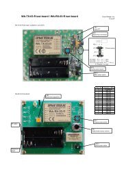
TERMINAL DESCRIPTION<br />
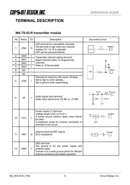
<strong>WA</strong>-<strong>TX</strong>-<strong>03</strong>-R transmitter module<br />
No. Name I/O Description Equivalent circuit<br />
1 UNA O<br />
2 SW0 I<br />
3 SW1 I<br />
4 SW2 I<br />
5 SW3 I<br />
6 NC -<br />
7 NC -<br />
8 STB I<br />
LED terminal for unavailable channels.<br />
The terminal is high when any channel<br />
outside CH 1 to 15 is selected.<br />
LED can be powered directly<br />
Transmitter channel setting terminal<br />
Select channel within 15 programmed<br />
channels<br />
Refer to “Channel table”<br />
Terminal for stand-by with power off delay<br />
Set to high to enter standby.<br />
Set to ground when transmitting.<br />
9 AF I<br />
Audio signal input terminal<br />
Audio input signal level -93 dBv to -13 dBv<br />
10 VCC I<br />
Power supply (+) terminal<br />
Voltage range is DC 4.2 to 6 V<br />
A power source without ripple noise should<br />
be used.<br />
A protection diode for reverse connection is<br />
provided in the circuit.<br />
11 ANT O<br />
Antenna terminal (RF output)<br />
50 Ω impedance<br />
12 GND I<br />
GND terminal<br />
The ground is for the power supply and<br />
antenna radial.<br />
Connect it to a wide ground plane for efficient<br />
antenna emissions and stable operation.<br />
OG_<strong>WA</strong>-<strong>03</strong>-R_V15e <strong>Circuit</strong> <strong>Design</strong>, <strong>Inc</strong>. 5