RSIF Power Venter RSIF Power Venter - Enervex
RSIF Power Venter RSIF Power Venter - Enervex
RSIF Power Venter RSIF Power Venter - Enervex
- No tags were found...

You also want an ePaper? Increase the reach of your titles
YUMPU automatically turns print PDFs into web optimized ePapers that Google loves.
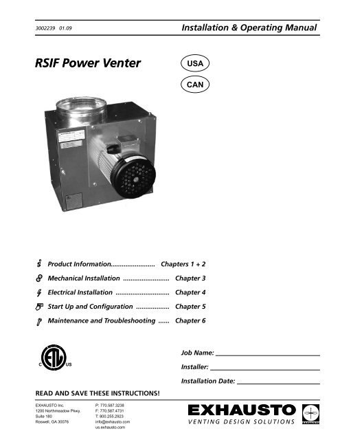
3002239 01.09 Installation & Operating Manual<br />
<strong>RSIF</strong> <strong>Power</strong> <strong>Venter</strong><br />
USA<br />
CAN<br />
Product Information........................ Chapters 1 + 2<br />
Mechanical Installation<br />
......................... Chapter 3<br />
Electrical Installation<br />
............................. Chapter 4<br />
Start Up and Configuration<br />
.................. Chapter 5<br />
Maintenance and Troubleshooting<br />
...... Chapter 6<br />
INTERTEK<br />
CM<br />
Job Name:<br />
C<br />
LISTED<br />
US<br />
Installer:<br />
Installation Date:<br />
READ AND SAVE THESE INSTRUCTIONS!<br />
EXHAUSTO Inc.<br />
1200 Northmeadow Pkwy.<br />
Suite 180<br />
Roswell, GA 30076<br />
P: 770.587.3238<br />
F: 770.587.4731<br />
T: 800.255.2923<br />
info@exhausto.com<br />
us.exhausto.com
3002239 01.09<br />
1. Product Information<br />
2. Specifications<br />
3. Mechanical Installation<br />
4. Electrical Installaion<br />
5. Startup & Configuration<br />
1.1 Function........................................................................................................................... 3<br />
1.2 Components..................................................................................................................... 3<br />
1.3 Shipping........................................................................................................................... 4<br />
1.4 Warranty........................................................................................................................... 4<br />
2.1 Dimensions & Capacities................................................................................................. 5<br />
3.1 Positioning........................................................................................................................ 6<br />
3.2 Mounting of <strong>Power</strong> <strong>Venter</strong>................................................................................................ 7<br />
3.3 Connection to Chimney or Vent....................................................................................... 8<br />
<strong>RSIF</strong> 146.......................................................................................................................... 8<br />
<strong>RSIF</strong> 160/180................................................................................................................... 9<br />
3.4 Installation of Stack Probe for Proven Draft Switch Function......................................... 10<br />
4.1 Electrical Requirements..................................................................................................11<br />
4.2 Wiring the Fan to a Fan Speed Control and Proven Draft Switch...................................11<br />
4.3 Wiring the Fan to an EBC 10 Control............................................................................. 12<br />
5.1 System Testing............................................................................................................... 13<br />
5.2 Adjusting the Fan Speed................................................................................................ 13<br />
5.3 Adjusting the Proven Draft Switch Setting...................................................................... 13<br />
6. Maintenance & Troubleshooting<br />
6.1 Cleaning Intervals.......................................................................................................... 14<br />
6.2 Cleaning......................................................................................................................... 14<br />
6.3 Troubleshooting............................................................................................................... 15<br />
Symbol Legend:<br />
The following terms are used throughout this manual to bring attention<br />
to the presence of potential hazards or to important information<br />
concerning the product.<br />
Danger: Indicates an imminent hazardous situation<br />
which, if not avoided, will result in death, serious injury or<br />
substantial property damage.<br />
Caution: Indicates an imminent hazardous situation<br />
which, if not avoided, may result in personal injury or<br />
property damage.<br />
TO REDUCE THE RISK OF FIRE, ELECTRICAL SHOCK OR INJURY TO PERSONS,<br />
OBSERVE THE FOLLOWING:<br />
1. Use this unit in the manner intended by the manufacturer. If<br />
you have questions, contact the manufacturer at the address or<br />
telephone number listed on the front of the manual.<br />
2. Before servicing or cleaning the unit, switch off at service panel<br />
and lock service panel to prevent power from being switched on<br />
accidentally.<br />
3. Installation work and electrical wiring must be done by a qualified<br />
person(s) in accordance with applicable codes and standards.<br />
4. Follow the appliance manufacturer’s guidelines and safety<br />
standards such as those published by the National Fire Protection<br />
Association (NFPA), and the American Society for Heating,<br />
Refrigeration and Air Conditioning Engineers (ASHRAE), and the<br />
local code authorities.<br />
5. This unit must be grounded.<br />
How to use this manual<br />
This installation manual does not contain any system design<br />
documentation. System design documentation is available from any<br />
authorized EXHAUSTO representative.<br />
Accessories, fans and variable frequency drives are not covered by<br />
this manual. Please refer to these component’s individual manuals.
3002239 01.09<br />
1.1 Function<br />
Use<br />
1. Product Information<br />
The EXHAUSTO <strong>RSIF</strong> <strong>Power</strong> <strong>Venter</strong> is intended for use as an in-line power venter/draft inducer. It can be installed<br />
in-line in the chimney or stack and can be used for sidewall as well as vertical venting arrangements. It is specifically<br />
designed for applications where reliable and efficient operation, low noise level, low energy consumption, variable<br />
speed and compact design are of utmost importance. Typical uses are, but are not limited to: mechanical venting of<br />
gas-fired boilers and water heaters. The power venter should not operate with flue gas temperatures exceeding<br />
400°F (200°C). For indoor installation only.<br />
Construction<br />
The power venter housing is made of galvanized steel and insulated on all sides with fiberglass insulation material.<br />
The insulation assures a very low noise level and reduces the risk of condensation significantly. It also reduces the<br />
clearance to combustibles. The <strong>RSIF</strong> is equipped with an energy-efficient, totally enclosed, variable speed<br />
motor, which is mounted outside the air stream. A service door on the front of the power venter provides easy<br />
access to the inside of the power venter and the duct connections. The motor and impeller are mounted on the door.<br />
The motor is a direct drive, variable speed Class F insulated type. It has permanently lubricated, sealed ball<br />
bearings and is maintenance free.<br />
Listings<br />
The <strong>RSIF</strong> model is tested and listed to UL378, Standard for Draft Equipment and CSA CAN3-B255-M81, Standard<br />
for Mecanical Flue-Gas Exhausters. This installation manual does not contain any system design documentation.<br />
Please refer to the system design manuals or instructions by EXHAUSTO.<br />
Restrictions<br />
The <strong>RSIF</strong> <strong>Power</strong> <strong>Venter</strong> should only be used with appliances operating on Natural Gas or LP-Gas/Butane. It should<br />
never be used with incinerators, incinerating toilets or solid-fuel burning equipment. When used with multiple<br />
appliances and a Fan Speed Control to control the fan speed, a barometric damper should be installed<br />
to prevent overdraft conditions, unless the appliance(s) have a draft hood or a draft diverter. This limitation does<br />
not apply when used with an EBC 10, EBC 12 or EBC 30 Pressure Control. The temperature of the flue gases going<br />
through the power venter should never exceed 400°F (200°C).<br />
1.2 Components<br />
The power venter consists of the following components:<br />
a. Housing f. Door latches<br />
b. Access door g. Door handle<br />
c. Motor h. Support legs with vibration dampers (2)<br />
d. Centrifugal impeller i. Sheet metal screws (4)<br />
e. <strong>Power</strong> venter housing l. Wire conduit<br />
Fig. 1<br />
<br />
3/20
3002239 01.09<br />
1.3 Shipping<br />
Protection<br />
The power venter is protected by a corrugated box. Do not place other products or items on top of the box.<br />
After unpacking, the product must be handled in a way to prevent damaging the collars and the power venter<br />
housing.<br />
Fig. 2<br />
Never operate the power venter with the access door open!<br />
To open access door, loosen screws on latch handles and raise handles.<br />
Standard Packing<br />
The power venter is shipped with the motor installed on the access door, (2) legs with screws, (2) gaskets for<br />
the <strong>RSIF</strong> 160/180, and Installation and Operating Manual . If any other components are shipped, these will<br />
appear on the shipment packing list.<br />
NOTE:<br />
1.4 Warranty<br />
All single phase fans are shipped with a capacitor and junction box connected via conduit. The capacitor is<br />
located INSIDE the junction box. Please do not discard.<br />
EXHAUSTO products are warranted for a period of two (2) years following the date of invoice.<br />
Replacement or repair will be at EXHAUSTO’s discretion, provided factory inspection shows a defect<br />
in material or workmanship.<br />
Complete warranty conditions are available from EXHAUSTO.
3002239 01.09<br />
2. Specifications<br />
2.1 Dimensions & Capacities<br />
Model <strong>RSIF</strong> 146 <strong>RSIF</strong> 160 <strong>RSIF</strong> 180<br />
Fan Type<br />
Centrifugal Impeller (F-Wheel)<br />
Motor Type<br />
TEFC<br />
Voltage VAC 1x120<br />
Amperage Amps 1.2 2.9 5.8<br />
Motor Output HP 1/10 1/5 1/2<br />
kW 0.08 0.16 0.35<br />
RPM 1600<br />
Weight lbs 28 38 60<br />
kg 13 17 27<br />
Duct Connection E in 6 8 8<br />
mm 153 200 200<br />
Dimensions A in 13.60 14.57 16.15<br />
mm 345 370 410<br />
B in 11.62 12.60 13.98<br />
mm 295 320 355<br />
C in 7.88 9.26 9.26<br />
mm 200 235 235<br />
D in 4.33 5.52 7.68<br />
mm 110 140 195<br />
G in 13.78 15.75 15.75<br />
mm 350 400 400<br />
H in 6.50 7.10 7.88<br />
mm 165 180 200<br />
J in 7.88 8.27 9.26<br />
mm 200 210 235<br />
K in 4.33 5.12 5.12<br />
mm 110 130 130<br />
R in 13.60 14.57 16.15<br />
mm 345 370 410<br />
Capacity Chart
3002239 01.09<br />
3. Mechanical Installation<br />
!<br />
Warning: Failure to install, maintain and/or operate the <strong>RSIF</strong> <strong>Power</strong> <strong>Venter</strong> in<br />
accordance with the manufacturer’s instructions may result in conditions, which can<br />
produce bodily injury and property damage.<br />
The <strong>RSIF</strong> must be installed by a qualified installer in accordance with these instructions and all local codes or in their<br />
absence with the latest edition of The National Fuel Gas Code (NFPA54/ANSI Z223.1) or NFPA 211 when<br />
applicable. Preferably, the <strong>RSIF</strong> should be installed as close to the termination as possible. It can also be<br />
installed at the outlet of a heating appliance, in the breeching itself, or in the transition from breeching to vertical<br />
chimney. It can also be used for sidewall vented applications where it discharges through a wall. It<br />
is for indoor installation only. Unless installed adjacent to the wall it is discharging through, the chimney material<br />
used on the discharge side must be airtight. Traditional gas vent (B-vent) is not considered airtight.The<br />
<strong>RSIF</strong> 146 is designed to fit any type of nominal 6” diameter vent pipe, while the <strong>RSIF</strong> 160 and 180 fit a nominal 8”<br />
diameter vent pipe. Special adapters are available for easy installation in the field. See Section 3.3. The vent<br />
pipe must be installed and supported according to the chimney manufacturer’s instructions and/or in accordance<br />
with NFPA54 and NFPA211.<br />
3.1 Positioning<br />
The power venter can be installed in many different positions. However, it should always be possible to open<br />
the access door at least 80 degrees, and the door latches should always be accessible. Acceptable power<br />
venter positions are shown below in Fig. 3. Note that the power venter motor can never point straight down as this<br />
could cause condensation build-up around the shaft, which can shorten the product life.<br />
Never install the power venter so the motor points down. This will shorten the life.<br />
Fig. 3<br />
The <strong>RSIF</strong> can be used with any non-condensing gas-fired appliance. However, if serving a fan-assisted or forced<br />
draft appliance, a barometric damper must be installed in the connector.
3002239 01.09<br />
Typical installation arrangements<br />
Fig. 4<br />
3.2 Mounting of <strong>Power</strong> <strong>Venter</strong><br />
The power venter can be mounted with plumber’s strap or threaded rod with nuts and washers, or it can be<br />
placed on support legs (included). As Fig. 5 illustrates, the venter can be placed in virtually any position or direction,<br />
except with the motor pointing down. When placing the venter on the support legs (1), the vibration dampers<br />
(4) should be used and secured by nuts (2). The support legs are attached to the bottom of the venter using the<br />
enclosed sheet metal screws (3). In this configuration, the venter is typically placed on a shelf hung from a wall.<br />
If hanging the venter from the ceiling, threaded rods should be used. Attach the support legs (1) to the bottom of the<br />
fan and secure with the sheet metal screws (3). Do not use the vibration dampers. Instead, use the holes on the top<br />
of the legs for the threaded rods, and secure these with the nuts (5).<br />
Fig. 5
3002239 01.09<br />
3.3 Connection to Chimney or Vent<br />
Adapters are available for easy connection to standard venting systems.<br />
<strong>RSIF</strong> 146<br />
When used with B-vent, a B-vent adapter should be used. It slides into the vent inlet/outlet as shown below. Secure<br />
with sheet metal screws. B-vent or single wall vent slides over the B-vent adapter. Secure the vent with sheet<br />
metal screws.<br />
Fig. 6<br />
When used with a Pressure Stack, a PS-adapter should be installed, as shown below, and secured with sheet metal<br />
screws.<br />
Fig. 7<br />
NOTE: High temperature sealant should be used to seal the adapters on the outlet of the fan.
3002239 01.09<br />
<strong>RSIF</strong> 160/180<br />
When used with B-vent, or single wall pipe, place the enclosed gasket around the end of the inlet/outlet. Push the<br />
vent over the gasket and secure with sheet metal screws.<br />
Fig. 8<br />
When used with Pressure Stack, place the enclosed gasket around the end of the inlet/outlet and push the adapter<br />
over the gasket and secure with sheet metal screws.<br />
Fig. 9<br />
In order to achieve optimal performance and energy consumption, the vent pipe should be installed<br />
as in Fig. 10 and the distances observed.<br />
Fig. 10
3002239 01.09<br />
3.4 Installation of Stack Probe for Proven Draft Switch Function<br />
A safety system must be interlocked with the appliance. The safety system can utilize a Proven<br />
Draft Switch (PDS), a thermal switch, a flow switch or a sail switch. The device must be interlocked<br />
with the heating appliance(s) so it shuts down in case of insufficient draft, fan failure or power failure.<br />
Please refer to the PDS Installation Manual, EBC 12 Installation Manual or EBC 30 Installation Manual,<br />
if any of these controls are used.<br />
For more information about an alternative safety system, please consult EXHAUSTO.<br />
• Install the probe for the Proven Draft Switch (PDS) in the vent connector. The probe must<br />
be located between the appliance and the power venter. The probe must be located at<br />
least 3 vent diameters downstream of the draft hood, draft diverter, or barometric damper.<br />
The probe placement should also observe distances from elbows and Tees as shown in<br />
Fig. 11.<br />
• Drill ¼” hole for the probe, center the probe’s flange over the hole, and secure the flange<br />
with the two screws.<br />
• Insert the probe so the end of the probe is flush with the inner wall of the vent.<br />
• Install the PDS or the appropriate control within 6 feet of the probe location in<br />
the specified position.<br />
• Connect the probe to the PDS’ “LO” pressure port using the tubing. Make sure<br />
there are no sharp bends or kinks in the tubing.<br />
See Fig. 11 for more details<br />
Fig. 11<br />
Caution: A safety device that prevents heating appliance operation must be installed to<br />
prevent a hazardous situation in case of power failure to the fan or an inadequate draft<br />
situation.<br />
10
3002239 01.09<br />
4. Electrical Installation<br />
4.1 Electrical Requirements<br />
<strong>Power</strong> requirements depend on the power venter size. They can be found on page 5.<br />
Danger: Turn off electrical power before servicing. Contact with live electric components can<br />
cause shock or death.<br />
Notice: If any of the original wire supplied with the system must be replaced, use similar wire<br />
of the same temperature rating. Otherwise, insulation may melt or degrade, exposing bare wire.<br />
All wiring must be in compliance with the local codes, or in their absence, with the National Electric Code, NFPA70.<br />
All wiring should be appropriate Class 1 wiring as follows: installed in rigid metal conduit, intermediate metal conduit,<br />
rigid non-metallic conduit, electrical metallic tubing, or be otherwise suitably protected from physical damage.<br />
4.2 Wiring the Fan to a Fan Speed Control and Proven Draft Switch<br />
There are several ways of installing and operating the power venter depending on how it must operate for a certain<br />
application.<br />
The simplest way to operate the power venter is shown in Fig. 12. It involves interlocking the venter with the<br />
appliance using a relay controlled via the appliance. On a call for heat, the venter is energized. A PDS is<br />
interlocked with the appliance control. In case of insufficient draft, the appliance is shut down. A fan speed control<br />
can be used to set the initial draft and without further adjustment.<br />
Fig. 12<br />
24 VAC<br />
PROVEN DRAFT<br />
SWITCH<br />
ORANGE<br />
RED<br />
FAN<br />
MOTOR<br />
WHITE<br />
BLACK<br />
GREEN<br />
COM<br />
TR<br />
HOT<br />
TH<br />
24V GAS VALVE<br />
120/1/60<br />
N<br />
WEATHERPROOF BOX<br />
L<br />
NOTES:<br />
1<br />
FAN SPEED<br />
CONTROL<br />
All wiring must be in<br />
flexible or rigid metal<br />
conduit<br />
THE DISCONNECT MEANS AND CIRCUIT PROTECTION ARE TO<br />
BE PROVIDED BY THE INSTALLER OF THIS DEVICE<br />
LEGEND:<br />
24 VAC<br />
120 VAC<br />
11
3002239 01.09<br />
4.3 Wiring the Fan to an EBC 10 Control<br />
The EBC 10 control is a fan speed control for use with a single appliance. It is available with an internal or external<br />
Proven Draft Switch. When the system is activated, the fan will begin to operate. Once proper draft is achieved, the<br />
control will release the gas valve to allow fuel flow. In the event of electrical or mechanical failure, the control will<br />
turn off the gas valve. A connection diagram is shown in Fig. 13.<br />
Fig. 13<br />
12
3002239 01.09<br />
5. Startup & Configuration<br />
5.1 System Testing<br />
Before any adjustments are made to the system, follow these procedures:<br />
1. Turn the fan ON and make sure that it is operating. Increase and decrease the speed of the fan by<br />
adjusting the fan speed control to make sure it is operating properly.<br />
2. Turn the fan OFF and make sure the pressure switch opens, ensuring power to the circuit it controls is<br />
disconnected.<br />
Danger: Check other heating appliances (e.g. water heater, furnace, fireplace, etc.) for proper<br />
operation while the chimney fan is operating. Make sure no flue gases are spilling out as this can<br />
lead to carbon monoxide poisoning.<br />
5.2 Adjusting the Fan Speed<br />
Start up all appliances. Use the fan speed control to set the speed of the venter so no back pressure is<br />
experienced anywhere in the system. Check the system for flue gas spillage. Mark this setting on the fan speed<br />
control cover.<br />
5.3 Adjusting the Proven Draft Switch Setting<br />
Remove the snap-on cover from the conduit enclosure by loosening its retaining screw. Turn the slotted Adjustment<br />
Screw clockwise to raise the set point pressure and counter clockwise to lower the set point.<br />
Set the adjustment to its lowest position. With all appliances operating, reduce the speed of the fan to the set point,<br />
where the appliance(s) begins to spill flue gas. Increase the speed of the fan gradually to the point where there is no<br />
more spillage. Raise the switch’s set point so it opens. Return the fan speed to the original setting marked on the<br />
cover.<br />
The system is now adjusted so the flue gas spillage will disconnect the heating appliance(s).<br />
The procedure described here may not cover all Proven Draft Switches, so please review the Installation Manual for<br />
the switch being used.<br />
13
3002239 01.09<br />
6. Maintenance & Troubleshooting<br />
6.1 Cleaning Intervals<br />
The power venter is designed for prolonged use. It must be inspected and cleaned at least every 12 months. The<br />
need for cleaning is dependent on the type of application and how the power venter is operated.<br />
6.2 Cleaning<br />
Deposits should be removed from the impellers and the bottom of the power venter:<br />
1. Turn the fan off at the repair switch.<br />
2. When the blower wheel no longer rotates, open the access door.<br />
3. Clean the inside housing and the wheel with water containing a detergent.<br />
4. Dry all parts with a cloth.<br />
5. Close and secure the access door.<br />
6. Turn the fan on.<br />
If necessary, the blower wheel can be removed. Prior to removal, mark the position on the shaft. The placement of<br />
the wheel is also shown on a label placed on the inside of the access door.<br />
Do not remove the balancing weights on the impellers.<br />
Vibration in the draft inducer can be caused by a dirty impeller.<br />
14
3002239 01.09<br />
6.3 Troubleshooting<br />
Problem Probable Cause What to do<br />
Fan is making too much noise.<br />
Fan is vibrating and making noise.<br />
Ducting is too small for the volume of<br />
the air.<br />
Ducts/Filters are dirty/clogged.<br />
Fan inlet or outlet is too close to the<br />
customer.<br />
Damaged during shipping or<br />
installation.<br />
Dirt build-up on blower wheel.<br />
Fan and air ducts not installed with<br />
vibration dampers.<br />
Resize ducts.<br />
Clean and inspect ducts and filters.<br />
Relocate duct or fan.<br />
See if blower wheel is damaged or<br />
if motor shaft is bent. Replace if<br />
damaged.<br />
Clean wheel.<br />
Install vibration dampers.<br />
Fan is not working <strong>Power</strong> is off. Switch on power to the fan.<br />
Fan is getting power, but will not run.<br />
Fan is overheating and cycling on and<br />
off.<br />
Capacitor is not wired correctly.<br />
Fan speed control is bad.<br />
Blower wheel is stuck due to dirt buildup.<br />
Fan speed control is set too low.<br />
Motor bearings have seized. (Refer to<br />
section 1.1 “Use”.)<br />
Motor capacitor has failed. (Refer to<br />
section 1.1 “Use”.)<br />
Dirt build-up on blower wheel.<br />
Motor capacitor has failed. (Refer to<br />
section 1.1 “Use”.)<br />
Motor windings or bearings are failing.<br />
(Refer to section 1.1 “Use”.)<br />
Rewire connection.<br />
Bypass fan speed control. If fan now<br />
operates at 100%, replace fan speed<br />
control.<br />
Clean blower wheel.<br />
Set fan speed control to highest setting<br />
until fan is up to speed. Then reduce<br />
speed.<br />
See that the fan is operating within its<br />
design parameters. Replace the motor.<br />
Please refer to Fig. 12 and insure<br />
that capacitor is connected correctly.<br />
Check amp draw with and without the<br />
capacitor being connected. If amp<br />
draw is the same, replace capacitor.<br />
Clean blower wheel.<br />
Please refer to note in section above.<br />
Check amp draw. If incorrect, replace<br />
blower motor.<br />
15
3002239 01.09<br />
<strong>RSIF</strong> 146, <strong>RSIF</strong> 160, <strong>RSIF</strong> 180<br />
IEC 335-1, IEC 342-1, DS/EN 292-1, DS/EN 292-2<br />
89/392, 91/368, 93/44<br />
14.05.2002<br />
EXHAUSTO Inc.<br />
1200 Northmeadow Pkwy.<br />
Suite 180<br />
Roswell, GA 30076<br />
P: 770.587.3238<br />
F: 770.587.4731<br />
T: 800.255.2923<br />
info@exhausto.com<br />
us.exhausto.com