MEC 18 Mechanical Exhaust Control - Enervex
MEC 18 Mechanical Exhaust Control - Enervex
MEC 18 Mechanical Exhaust Control - Enervex
- No tags were found...

Create successful ePaper yourself
Turn your PDF publications into a flip-book with our unique Google optimized e-Paper software.
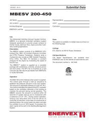
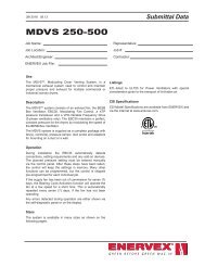
3916010 11.084.2 Continuous Fan OperationFor continuous fan operation, connect the fan to the control as described below.• Connect a 1x120 VAC power supply to terminals 1, 2 and 3.• Jump terminals 5 and 9.• Jump terminals 6 and 8.• Connect the appliance:- Connect the start signal from the appliance to terminals 14 and 15.• Connect the fan:- If using a 1x120V fan, connect it to terminals 19, 20 and 21. Refer Fig. 7 and the fan’s InstallationManual.- If using a 3-phase fan and VFD, connect the VFD to terminals 25 and 26 as shown in Fig. 10 and 11.DO NOT connect the fan directly to the <strong>MEC</strong> <strong>18</strong> control.• Connect the transducer (XTP) to terminals 22, 23 and 24.Fig. 7<strong>MEC</strong> <strong>18</strong> <strong>Control</strong> Board0 +V E N T I N G D E S I G N S O L U T I O N S
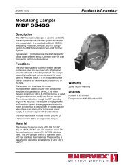
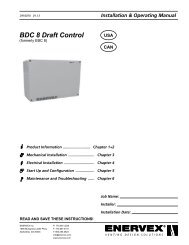
3916010 11.084.3 Intermittent Fan OperationThe control can be set up for intermittent operation in one of two ways:It can be interlocked directly with the appliance control or with a dry set of contacts.Interlock with ApplianceFig. 8 shows how an appliance control signal (10-120V AC/DC) is connected to the <strong>MEC</strong> <strong>18</strong>:• Connect the power supply to terminals 1, 2 and 3.• Connect the appliance:- Connect the appliance start signal to terminal 4.- Jump terminals 5 and 14.- The start signal to the appliance is now activated by terminal 15.- Connect Neutral to terminal 6.• Connect the fan:- If using a 1x120V fan, connect the fan to terminals 19, 20 and 21. Make sure the neutral line isdedicated to the fan and control (term. 20) only. Refer to the fan’s Installation Manual.- If using a 3-phase fan and VFD, connect the VFD to terminals 25 and 26 as shown in Fig. 10 and 11.DO NOT connect the fan directly to the <strong>MEC</strong> <strong>18</strong> control.• Connect the transducer (XTP) to terminals 22, 23 and 24.Fig. 8Sample Wiring Diagram - Appliance InterlockConnection to 120V Fan - Intermittent Operation<strong>MEC</strong> <strong>18</strong> <strong>Control</strong> Board0 +V E N T I N G D E S I G N S O L U T I O N S
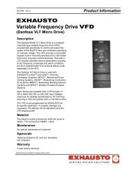
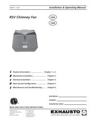
3916010 11.08Interlock with dry set of contactsFig. 9 shows how a dry set of contacts is connected to the <strong>MEC</strong> <strong>18</strong>:• Connect the power supply to terminals 1, 2 and 3.• Connect the appliance:- Connect the dry set of contacts to terminals 6 and 8.- Jump terminals 4 and 9.- Connect the start signal to the appliance to terminals 14 and 15.• Connect the fan:- If using a 1x120V fan, connect the ventilator or fan to terminals 19, 20 and 21. Refer to the fan’sInstallation Manual.- If using a 3-phase fan and VFD, connect the VFD to terminals 25 and 26 as shown in Fig. 10 and 11.DO NOT connect the fan directly to the <strong>MEC</strong> <strong>18</strong> control.• Connect the XTP transducer to terminals 22, 23 and 24.Fig. 9<strong>MEC</strong> <strong>18</strong> <strong>Control</strong> Board0 +V E N T I N G D E S I G N S O L U T I O N S10
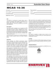
3916010 11.084.4 Connection to a Variable Frequency DriveTo connect the 3-phase fan and variable frequency drive (VFD), connect the VFD to terminals 25 and 26 of the <strong>MEC</strong> <strong>18</strong>.DO NOT connect the fan directly to the control.Wire the VLT 2800 Model variable frequency drive according to Fig. 10.Fig. 10Wire the VLT Micro Drive variable frequency drive according to Fig. 11.Fig. 1111V E N T I N G D E S I G N S O L U T I O N S
3916010 11.084.5 Integrated with External PDSFig. 12 shows how to connect a external Proven Pressure Switch (PDS) to the <strong>MEC</strong> <strong>18</strong>. The external PDS is a backupto the integrated PDS and both must be satisfied by sufficient pressure to release the appliance:• Remove the factory installed jumper over terminals 16 and <strong>18</strong>.• Connect the switch to terminals 16, 17 and <strong>18</strong> as shown in Fig. 11.Fig. 12<strong>MEC</strong> <strong>18</strong> <strong>Control</strong> BoardV E N T I N G D E S I G N S O L U T I O N S12
3916010 11.085. Startup and Configuration5.1 GeneralPrior to start up please review the paragraph below titled Dipswitch settings.Dipswitch settingsPrior to starting the system, check to see if the dipswitch settings are as required:• Default factory setting: All OFF• If the factory setting must be changed, remove the black cover plate to gain access to thedipswitches (see Fig 12-A):1. Remove the potentiometer dial.2. Remove the (4) flathead screws and lift the top plate off the board.3. Change the dipswitch settings.Dipswitch Name OFF ON1 MANUALRESETAutomatic resetat power failure orinsufficient pressure.Manual reset atpower failure orinsufficient pressure.2 POSTPURGENo post-purge.3 minutes of postpurge.3* PDS CHECK No monitoring to seeif the PDS was in NCposition prior to start.The PDS must be inNC prior to start.* Always OFF if the Proven Pressure Switch (PDS) is not connected.Fig. 1213V E N T I N G D E S I G N S O L U T I O N S
3916010 11.08EN 60 335-1, EN 60 335-2-80, DS/EN ISO 12100-1:2003, DS/EN ISO 12100-2:200398/37/EF/-EEC/-EWG/-CEELangeskov, 01.03.2005EXHAUSTO Inc.1200 Northmeadow Pkwy.Suite <strong>18</strong>0Roswell, GA 30076P: 770.587.3238F: 770.587.4731T: 800.255.2923info@exhausto.comus.exhausto.comV E N T I N G D E S I G N S O L U T I O N S