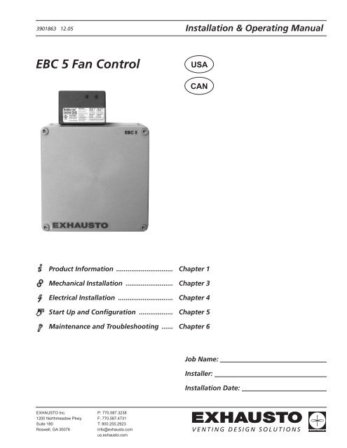
EBC 5 Fan Control - Enervex
EBC 5 Fan Control - Enervex
EBC 5 Fan Control - Enervex
Create successful ePaper yourself
Turn your PDF publications into a flip-book with our unique Google optimized e-Paper software.
3901863 12.054.1 General4. Electrical InstallationDanger: Turn off electrical power before servicing. Contact with live electric components cancause shock or death.!<strong>EBC</strong> 5 is designed for 1x120VAC power supply only.The control is connected so the fan runs internittently dependent on appliance operation.The system has an Integrated Proven Draft Switch.The terminals wire call outs are shown below:<strong>EBC</strong>5 RIBU2C Relay<strong>EBC</strong>5 <strong>Control</strong> BoardWireWhite/YellowWhite/BlueWhite/BlackYellowOrangeBlueWhite/PurpleGrey/WhiteWhite/RedPurpleBrownGreyUseCoil - COM10-30V Coil120v CoilRelay 1 - COMRelay 1 - NORelay 1 - NCCoil - COM10-30V Coil120V CoilRelay 2 - COMRelay 2 - NORelay 2 - NC}}Operating Signal to<strong>EBC</strong> 5 controlProven DraftOutputWireRedBlackBlackWhiteBrownOrangePurpleBlueYellowUseNeutral to <strong>Fan</strong>Line Voltage to <strong>Fan</strong>Power Supply - Line VoltagePower Supply - NeutralSTRS1S3ALMISO7
3901863 12.054.2 Wiring Diagram for Use with Heating ApplianceThe wiring diagram below shows the <strong>EBC</strong> 5 wired with a heating appliance, where a connection to a gas-solenoidvalve provides the safety.In case of insufficient draft or electrical/mechanical failure, the control shuts off the gas supply, which will cause theheating appliance to shut down.<strong>EBC</strong> 5FANMOTORPOWER SUPPLY120/1/60COML24VACNTRANSFORMER120/24VACW/BlueEXHAUSTOW/YellowBrownBlackWhiteBlackRedCapacitorRedWhiteBlackGreenJunction Box10-30vCOMTRHOTTH24V GAS VALVEN L1POWER SUPPLY1 x 120 V AC8
3901863 12.05The wiring diagram below shows the <strong>EBC</strong> 5 wired with a heating appliance, where a connection to the appliance’ssafety circuit provides the safety.In case of insufficient draft or electrical/mechanical failure, the Proven Draft Switch and the control open the safetycircuit to prevent operation, which will make the appliance shut down.<strong>EBC</strong> 5FANMOTORJunction BoxGreenBlackWhiteRedCapacitorEXHAUSTORedBlackBlackWhiteW/YellowBrownPurpleW/BlackW/Blue120vac10-30v(OR)THERMOSTATBURNERCONTROLN/COML1N L1POWER SUPPLY1 x 120 V ACPOWER SUPPLYAPPLIANCE CONTROL9
3901863 12.054.3 Wiring for Use with A Gas-fired FireplaceThe wiring diagram below shows how the <strong>EBC</strong> 5 connected to a gas-fired fireplace system.The call for heat is activated by turning the system on using a wall switch. Once proper draft is achieved thecontrol will release the gas-valve and allow the flow of fuel. When turning the switch off, the control willshut down the flow of fuel, which turns off the fireplace. In case of insufficient draft or mechanical/electricalfailure, the Proven Draft Switch and the control will shut off the gas valve and the flow of fuel.<strong>EBC</strong> 5FANMOTORPOWER SUPPLY120/1/60COML24VACNTRANSFORMER120/24VACW/BlueEXHAUSTOW/YellowBrownBlackWhiteBlackRedCapacitorRedWhiteBlackGreenJunction Box10-30vWALL SWITCHCOMTRHOTTH24V GAS VALVEN L1POWER SUPPLY1 x 120 V AC10
3901863 12.055.1 General5. Startup and ConfigurationThe purpose of this control is to ensure safe venting for a single appliance where modulation is not required. Thisis accomplished by starting a chimney fan/power venter when the appliance calls for heat and stopping the fanwhen the heat demand has been satisfied.5.2 Sequence of OperationStartSequenceOperatingSequenceShutdownSequence1. The appliance activates the <strong>EBC</strong> 5 Relay to initiate the call for heat.2. The <strong>EBC</strong> 5 control sets fan output to 100% for a 15 seconds pre-purge cycle.3. The Proven Draft Switch closes when adequate draft has been achieved.4. The <strong>EBC</strong> 5 control releases the appliance for operation by activating the <strong>EBC</strong> 5 Relay.1. The control adjusts fan output to the percentage set by DIP switches 3-8.2. If the Proven Draft Switch opens, fan output is set to 100% and a 15 seconds timing cycle starts.3. If the Proven Draft Switch does not close within 15 seconds, the fan out turns off and an alarm condition exist.4. If the Proven Draft Switch closes, the control automatically resumes step 1.1. The call for heat signal from the appliance is turned off.2. <strong>Fan</strong> output continues at the pre-set speed for 0, 30, 60 or 90 seconds as set by Post-Purge DIP switches 1 and 2.3. <strong>Fan</strong> output is set to zero5.3 Adjusting <strong>Fan</strong> SpeedThe fan speed can be adjusted by setting DIP switches inside the control according to this table:ON1 2 3 4 5 6 7 8DIP Switches (shown inOFF position)<strong>Fan</strong> Speed OutputSpeed DIP3 DIP4 DIP5 DIP6 DIP7 DIP830% OFF OFF OFF OFF OFF OFF42% ON OFF OFF OFF OFF OFF54% ON ON OFF OFF OFF OFF65% ON ON ON OFF OFF OFF77% ON ON ON ON OFF OFF89% ON ON ON ON ON OFF100% ON ON ON ON ON ON5.4 Setting Post-Purge DelayThe Post-Purge delay can be adjusted by setting the DIP switches inside the control according to this table:Post-Purge DelayTime DIP1 DIP20 sec OFF OFF30 sec ON OFF60 sec OFF ON90 sec ON ON11
3901863 12.056. Maintenance and TroubleshootingObservation Problem SolutionHeating appliance/fireplace cycle on andoff- <strong>Fan</strong> speedcontrol is settoo low.- <strong>Fan</strong> speedcontrol is bad- Increase fan speed setting- Replace fan speed control.<strong>Fan</strong> is ‘hunting’(increasing speed andthen decreasing speedconstantly)Heating appliance/fireplace will not comeonHeating appliance/fireplace will not shutoff- <strong>Fan</strong> speedcontrol is settoo low.- Proven draftswitch setting istoo high- <strong>Fan</strong> is notworking- No power tothe <strong>EBC</strong> 5- Provendraft switch isnot properlyconnected tothe chimney.- Relay orproven draftswitch is bad- Proven draftswitch is notwired correct- <strong>EBC</strong> 5 is notwired correctly- Relay orproven draftswitch is bad- Increase fan speed setting.- Lower the pressure setting on the proven draft switch- Check the fan and if necessary, repair or replace. Check wiring, it may not be receivingstart command.- Connect power to <strong>EBC</strong> 5- Make sure the probe is properly inserted into the stack, so the tip of the probe is flushwith the inside of the chimney. If serving a fireplace the probe should be 3 to 4 below thefan. If serving a heating appliance it should be 2-4 feet away from appliance outlet.- Replace relay or switch- Check wiring and correct.- Check wiring and correct.- Replace relayEXHAUSTO Inc.1200 Northmeadow Pkwy.Suite 180Roswell, GA 30076P: 770.587.3238F: 770.587.4731T: 800.255.2923info@exhausto.comus.exhausto.com


