EBC 12 Modulating Fan Control - Enervex
EBC 12 Modulating Fan Control - Enervex
EBC 12 Modulating Fan Control - Enervex
- No tags were found...

Create successful ePaper yourself
Turn your PDF publications into a flip-book with our unique Google optimized e-Paper software.
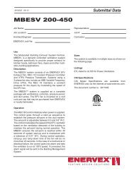
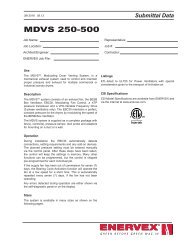
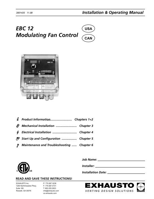
In. WC / PaSetpoint Reset Alarm3001435 11.082. Specifications2.1 Dimensions & Capacities<strong>EBC</strong> <strong>12</strong> <strong>Control</strong>Power supply V 1x<strong>12</strong>0VACAmperage A 6.3Operating temperature °F/°C -4 to <strong>12</strong>2/-20 to 50Range of operation inWC/Pa 0-0.6/0-150Tolerance inWC/Pa 0.01/3+/-10%<strong>Control</strong> signal mA max. 10<strong>Control</strong> relayMax. <strong>12</strong>0 VAC/8AOutput VAC 10-<strong>12</strong>0VDC 0-10Dimensions A in/mm 6.9/175B in/mm 8.1/205C in/mm 4.0/102Weight lbs/kg 3.0/1.5EMC standard Emission EN50 081-1Immunity EN50 082-2XTP-sensorPower supply VDC 0-24Amperage mA +24V-+0-10V-COM+0-10VFig. 1-EFig. 1-FFig. 1-GPotentiometer for draft settingDisplayLEDs (yellow) showingincreasing/decreasing speedFig. 1-HDipswitch blockFig. 1-ILEDs (green) showing ON/OFFstatusIRD10103V E N T I N G D E S I G N S O L U T I O N S
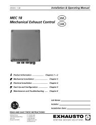
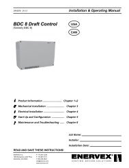
3001435 11.083. Mechanical Installation3.1 LocationThe control and the transducer must be installed inside, preferably in the boiler room. The control does not need tobe installed in an enclosure. Fig. 2 shows how the components are connected.The transducer cannot be mounted inside an airtight enclosure. It uses the boiler roompressure/atmospheric pressure as reference pressure.Fig. 2Fig. 2a3.2 Mounting of <strong>Control</strong>The control can be mounted directly on a wall or similar. Remove the clear cover. The mounting holes are locatedunder the plastic screws that hold the cover in place (Fig. 3).The distance between the control and the transducer should not exceed three hundred (300) feet.Fig. 3<strong>EBC</strong> <strong>12</strong>V E N T I N G D E S I G N S O L U T I O N S
3001435 11.083.3 Mounting of TransducerAttention must be paid to the position and location of the transducer. Fig. 4 shows the required position. Failure tofollow this instruction may result in an inoperable system.The transducer should be mounted within six (6) feet of the stack probe.Fig. 43.4 Mounting of Stack ProbeThe probe (Fig. 2a on page 5) is inserted into the chimney or vent at the point where the draft should be kept constant.This could be at the appliance outlet, in the vent or similar.Referring to Fig. 2, make sure the tip of the tube is flush with the inner wall of the stack. Inserting it too far may affectthe reading and thereby the operation.3.5 Connecting Transducer to Stack ProbeThe transducer is connected to the stack probe via a silicone tube. Make sure that the tube is connected to the propertransducer port as shown in Fig. 5.Fig. 5Front- +V E N T I N G D E S I G N S O L U T I O N S
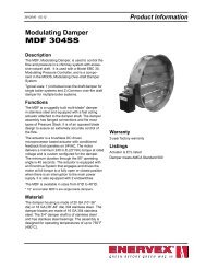
3001435 11.084. Electrical Installation4.1 GeneralDanger: Turn off electrical power before servicing. Contact with live electric components cancause shock or death.<strong>EBC</strong> <strong>12</strong> is designed for 1x<strong>12</strong>0VAC power supply only. <strong>Fan</strong> output is regulating on the neutral sideand cannot be connected to other circuits.The control can be used in two ways:• Connected so the fan runs continuously independent of appliance operation (see paragraph 4.2).• Interlocked with an appliance so the appliance operation indirectly controls the fan operation (seeparagraph 4.3).In both cases the control will still monitor and maintain a constant draft.There are two types of safety systems available:• Integrated Proven Draft Switch (standard).• Integrated Proven Draft Switch with External Proven Draft Switch (accessory) backup (see paragraph4.4).The terminals are connected as shown on Fig. 6:Terminal Use1 Power Supply-L<strong>12</strong> Power Supply-N3 Power Supply-Ground4-5 Voltage Input from Appliance thermostatOptocoupler (-) (10-<strong>12</strong>0VAC/CDC6-7 Voltage Input from Appliance thermostatOptocoupler (+) (10-<strong>12</strong>0VAC/DC)8 24VDC power supply to dry set ofcontacts (appliance thermostat)9 0VDC power supply to dry set ofcontacts (appliance thermostat)14 Burner relay contact-Common(max. <strong>12</strong>0 VAC, 8 Amps.)15 Burner relay contact-Normally Open(max. <strong>12</strong>0VAC, 8 Amps.)16 PDS-C (Common) Proven Draft SwitchTerminal Use17 PDS-NC (Normally Closed) ProvenDraft Switch18 PDS-NO (Normally Open) ProvenDraft Switch19 Chimney <strong>Fan</strong>-L<strong>12</strong>0 Chimney <strong>Fan</strong>-N (regulating)21 Chimney <strong>Fan</strong>-Ground22 XTP-0VDC Power Supply(transducer)23 XTP-24VDC Power Supply(transducer)24 XTP-0-10VDC Return Signal(transducer)25 <strong>Control</strong> signal 0VDC26 <strong>Control</strong> signal 0-10VDCFig. 6+24V+24VCOM-0+24V-+__ >0-10V-COM+0-10VV E N T I N G D E S I G N S O L U T I O N S
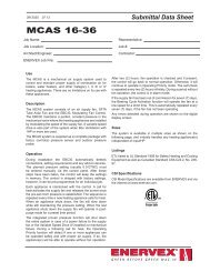
3001435 11.084.2 Continuous Chimney <strong>Fan</strong> OperationFig. 7 shows how to connect a chimney fan to the <strong>EBC</strong> <strong>12</strong> if continuous operation is needed:• Connect the power supply to terminals 1, 2 and 3.• Jump terminals 5 and 9.• Jump terminals 6 and 8.• Connection to the appliance(s):- Connect the start signal from the burner to terminals 14 and 15.• To connect the chimney fan:- If using a 1x<strong>12</strong>0V chimney fan, connect it to terminals 19, 20 and 21. Refer to the fan’s InstallationManual.- If using a 3-phase fan and VFD, connect the VFD to terminals 25 and 26 as shown in Fig. 10 and 11.DO NOT connect the fan directly to the MEC 18 control.• Connect the XTP transducer to terminals 22, 23 and 24.Fig. 7<strong>EBC</strong> <strong>12</strong> <strong>Control</strong> Board0 +V E N T I N G D E S I G N S O L U T I O N S
3001435 11.084.3 Intermittent Chimney <strong>Fan</strong> Operation (<strong>12</strong>0V)The control can be interlocked with an appliance in two ways:It can be interlocked directly with an appliance control, or with a dry set of contacts.Interlock with BurnerFigure 8 shows how an appliance control signal (10-<strong>12</strong>0V AC/DC) is connected to the <strong>EBC</strong> <strong>12</strong>:• Connect the power supply to terminals 1, 2 and 3.• Connection to the appliance:- Connect the boiler start signal to terminal 4.- Jump terminals 5 and 14.- The start signal to the burner is now activated by terminal 15.- Connect Neutral to terminal 6.• To connect the chimney fan:- If using a 1x<strong>12</strong>0V chimney fan, connect it to terminals 19, 20 and 21. Refer to the fan’s InstallationManual.- If using a 3-phase fan and VFD, connect the VFD to terminals 25 and 26 as shown in Fig. 10 and 11.DO NOT connect the fan directly to the MEC 18 control.• The XTP-transducer is connected to terminals 22, 23 and 24.Fig. 8Sample Wiring Diagram - Burner InterlockConnection to <strong>12</strong>0V <strong>Fan</strong> - Internittent Operation<strong>EBC</strong> <strong>12</strong> <strong>Control</strong> Board0 +V E N T I N G D E S I G N S O L U T I O N S
3001435 11.08Interlock with dry set of contactsFigure 9 shows how a dry set of contacts is connected to the <strong>EBC</strong> <strong>12</strong>:• Connect the power supply to terminals 1, 2 and 3.• Connection to the appliance:- Connect the dry set of contacts to terminals 6 and 8.- Jump terminals 4 and 9.- Connect the start signal to the burner to terminals 14 and 15.• To connect the chimney fan:- If using a 1x<strong>12</strong>0V chimney fan, connect it to terminals 19, 20 and 21. Refer to the fan’s InstallationManual.- If using a 3-phase fan and VFD, connect the VFD to terminals 25 and 26 as shown in Fig. 10 and 11.DO NOT connect the fan directly to the MEC 18 control.• Connect the XTP transducer to terminals 22, 23 and 24.Fig. 9Sample Wiring Diagram - Dry Contact RelayConnection to <strong>12</strong>0V <strong>Fan</strong><strong>EBC</strong> <strong>12</strong> <strong>Control</strong> Board0 +V E N T I N G D E S I G N S O L U T I O N S10
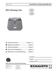
3001435 11.084.4 Connection to a Variable Frequency DriveTo connect the 3-phase fan and variable frequency drive (VFD), connect the VFD to terminals 25 and 26 of the <strong>EBC</strong> <strong>12</strong>.DO NOT connect the fan directly to the control.Wire the VLT 2800 Model variable frequency drive according to Fig. 10.Fig. 10Wire the VLT Micro Drive variable frequency drive according to Fig. 11.Fig. 11TO <strong>EBC</strong> <strong>12</strong>CONTROL11V E N T I N G D E S I G N S O L U T I O N S
3001435 11.084.5 Integrated Proven Draft Switch with External Proven Draft Switch BackupFig. <strong>12</strong> shows how to connect a external Proven Draft Switch (PDS) to the <strong>EBC</strong> <strong>12</strong>. The external PDS is abackup to the integrated PDS and both must be satisfied by sufficient draft to release the appliance:• Remove the factory installed jumper over terminals 16 and 18.• Connect the switch to terminals 16, 17 and 18 as shown on Fig. 11.Fig. <strong>12</strong><strong>EBC</strong> <strong>12</strong> <strong>Control</strong> BoardV E N T I N G D E S I G N S O L U T I O N S<strong>12</strong>
3001435 11.085. Startup and Configuration5.1 GeneralPrior to start up please review the paragraph below titled Dipswitch settings.Dipswitch settingsPrior to starting the system, check to see if the dipswitch settings are as required:• Default factory setting: All OFF• If the factory setting must be changed, the black cover plate must be removed to gain access to thedipswitches (see Fig <strong>12</strong>-A):1. Remove the potentiometer dial.2. Remove the (4) flathead screws and lift the top plate off the board.3. Change the dipswitch settings.Dipswitch Name OFF ON1 MANUALRESETAutomatic resetat power failure orinsufficient draft.Manual reset atpower failure orinsufficient draft.2 POSTPURGENo post-purge.3 minutes of postpurge.3*) PDS CHECK No monitoring to seeif the PDS was in NCposition prior to start.The PDS must be inNC prior to start.*) Always OFF if the Proven Draft Switch (PDS) is not connected.Fig. <strong>12</strong>13V E N T I N G D E S I G N S O L U T I O N S
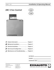
3001435 11.085.2 Setting Operating PressureThe pressure setting of the <strong>EBC</strong> <strong>12</strong> must be adjusted to assure proper draft for the heating system. The display (Fig.13-C) has two functions. It can show what the draft set-point is, and it can show what the actual draft is.The default mode shows the actual draft. To change the mode, the set-point button must be pressedcontinuously.To adjust the draft set-point follow this procedure:Temporary adjustment of the draft:1. Press the set-point button continuously with a pen or screwdriver (Fig. 13-A). The pressure setting willnow show on the display. Use the potentiometer (Fig. 13-B) to set the required draft in WC/Pa on thedisplay (Fig. 13-C). Release the set-point button; the actual draft will now show up on the display.2. Start the heating system and wait until the thermostat (Fig. 14-A) closes and the draft has stabilized(none of the yellow diodes are lit).Final adjustment of the draft:3. Check the draft at the appliance outlets and make any necessary adjustment by following the proceduredescribed under step 1 above.4. Check that the safety system disconnects the appliance (Fig. 14-B). An error can be simulated bydisconnecting the tube (-) to the transducer (XTP).5. Check the start function after the final draft setting adjustments have been made.Fig. 13<strong>EBC</strong> <strong>12</strong>EXHAUSTOCHIMNEY DRAFT TECHNOLOGYFig. 14A+24V+24VCOM-0+24V-+__ >0-10V-COM+0-10VV E N T I N G D E S I G N S O L U T I O N S14
3001435 11.086. Maintenance and TroubleshootingObservation Problem SolutionNo light in the SUPPLY diode (Fig 15-A) Blown fuse or interrupted power supply 1) Check the fuse (Fig. 15-B) and the fan power.2) Check the power supply.Constant light in “Increasing Speed” diode(Fig 15-E)System fault1) Check that the probe is connected to the “-” port on theXTP transducer.2) Check that the probe is not clogged.CAUTION: Do not blow into the XTP-transducer.3) Check that the fan is running.4) Set-point is too high for the fan capacity. Check/reducesetting.5) Check the entire system’s adjustment, including anybalancing baffles installed.6) Check breaching and common vent for leakages.7) Check the power supply to the XTP.Constant light in “Decreasing Speed” diode(Fig 15-D)Constant light in ALARM diode (Fig. 15-H), butno light in FAN diode (Fig. 15-G) (Can only occurwhen MANUAL RESET is ON (Fig. 15-F)Constant light in Alarm diodeand light in fan diode (Fig. 15-H)Flashing ALARM diode (Fig. 15-H)Can only occur when PDS CHECK is ON (Fig.15-F)The <strong>EBC</strong> <strong>12</strong> does not regulate and the fan isrunning at full speedSystem faultPower outageInsufficient draftError in safety system (PDS)The neutral connection is shared with otherdevices.1) The natural chimney draft prevents the system fromreaching the set-point. Check the adjustment. If necessary,install a balancing baffle or other resistance in the chimney.2) The probe may be in a bad location. Move it to anotherposition closer to the appliance.Press the RESET button (Fig. 15-C) for (1) second — seewarning.1) Press the RESET button (Fig. 15-C) — see warning.2) Check that the service disconnect switch is workingproperly.3) Check the connectors, chimney and fan for blockingrestrictions.1) Check that a PDS is installed.2) Check the setting of the safety system (the natural draftcan prevent close/alternatively the PDS CHECK dipswitch canbe moved to its OFF position.3) Check the connection to the PDS and the PDS itself.1) Check the amp-draw on terminal Nreg. If it is “0”, theneutral connection to the fan is being shared.Some appliances require a certain startup procedure after a shutdown. Follow this procedure priorto pressing the RESET button (Fig. 15-C).Fig. 1515V E N T I N G D E S I G N S O L U T I O N S
3001435 11.08EXHAUSTO Inc.<strong>12</strong>00 Northmeadow Pkwy.Suite 180Roswell, GA 30076P: 770.587.3238F: 770.587.4731T: 800.255.2923info@exhausto.comus.exhausto.comV E N T I N G D E S I G N S O L U T I O N S