Type 459 Determination of coefficent of discharge in case of lift restriction or back pressure Diagram for evaluation of ratio of lift / flow diameter (h/d 0 ) in reference to the coefficient of discharge (K dr /α w ) h = Lift [mm] d 0 = Flow diameter [mm] of selected safety valve, refer to table article numbers h/d 0 = Ratio of lift / flow diameter p a0 = Back pressure [bar a ] p 0 = Set pressure [bar a ] p a0/ p 0 = Ratio of back pressure / set pressure K dr = Coefficient of discharge acc. to DIN EN ISO 4126-1 α w = Coefficient of discharge acc. to AD 2000-Merkblatt A2 K b = Back pressure correction factor acc. to API 520 topic 3.3 d 0 Ø 9 mm d 0 Ø 13 mm d 0 Ø 17,5 mm 0,85 K dr = α w = f (h/d 0 ) – S/G 0,85 K dr = α w = f (h/d 0 ) – S/G 0,80 K dr = α w = f (h/d 0 ) – S/G 0,80 0,75 0,70 Coefficient of discharge K dr / αw 0,75 Ratio of lift / flow diameter h / d 0 Ratio of lift / flow diameter h / d 0 0,22 0,23 Ratio of lift / flow diameter h / d 0 0,65 0,60 0,70 0,55 0,65 0,50 0,45 0,60 0,40 0,55 0,35 0,30 0,50 0,25 0,45 0,10 0,15 0,20 0,25 0,15 0,05 0,1 0,15 0,2 0,25 0,20 0,05 0,1 0,15 Coefficient of discharge K dr / αw d 0 Ø 9 mm d 0 Ø 13 mm d 0 Ø 17,5 mm Coefficient of discharge K dr / αw 0,2 0,22 0,25 K dr = α w = f (h/d 0 ) – L 0,55 K dr = α w = f (h/d 0 ) – L 0,50 K dr = α w = f (h/d 0 ) – L 0,65 0,50 0,45 Type 459 Coefficient of discharge K dr / αw Ratio of lift / flow diameter h / d 0 Ratio of lift / flow diameter h / d 0 0,22 0,23 Ratio of lift / flow diameter h / d 0 0,40 0,55 0,45 0,35 0,50 0,40 0,30 0,45 0,35 0,25 0,40 0,30 0,20 0,35 0,25 0,15 0,30 0,20 0,10 0,05 0,1 0,2 0,25 0,05 0,1 0,15 0,2 0,25 0,05 0,1 0,15 Coefficient of discharge K dr / αw Coefficient of discharge K dr / αw 0,2 0,22 0,25 Diagram for evaluation of ratio of the coefficient of discharge (K dr /α w ) in reference to the ratio of back pressure / set pressure (p a0 /p 0 ) d 0 Ø 9 mm d 0 Ø 13 mm d 0 Ø 17,5 mm Coefficient of discharge K dr / αw 0,9 0,8 0,7 0,6 0,5 0,4 0,3 0,2 0,1 K dr = α w = f (p a0 /p 0 ) and K b = f (p a0 /p 0 ) 0,0 0,2 0,25 0,3 0,35 Ratio of back pressure / set pressure p a0 / p 0 How to use please refer to page 00/08 1,00 0,90 0,80 0,70 0,60 0,50 0,40 0,30 0,20 0,10 0 0,4 0,45 Back pressure correction factor K b Coefficient of discharge K dr / αw 0,9 0,8 0,7 0,6 0,5 0,4 0,3 0,2 0,1 K dr = α w = f (p a0 /p 0 ) and K b = f (p a0 /p 0 ) 0,0 0,2 0,3 0,4 0,5 0,6 0,7 0,8 Ratio of back pressure / set pressure p a0 / p 0 0,9 0,909 1,10 1,00 0,90 0,80 0,70 0,60 0,50 0,40 0,30 0,20 0,10 0,00 Back pressure correction factor K b Coefficient of discharge K dr / αw 0,9 0,8 0,7 0,6 0,5 0,4 0,3 0,2 0,1 K dr = α w = f (p a0 /p 0 ) and K b = f (p a0 /p 0 ) 0,0 0,2 0,3 0,4 0,5 0,6 0,7 Ratio of back pressure / set pressure p a0 / p 0 0,8 0,833 1,10 1,00 0,90 0,80 0,70 0,60 0,50 0,40 0,30 0,20 0,10 0,00 Back pressure correction factor K b 05/20 LWN 481.01-E
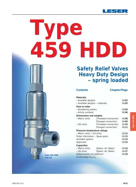
Type 459 HDD Safety Relief Valves Heavy Duty Design – spring loaded Contents Chapter/Page Type 459 HDD Cap H2 Materials • Available designs 06/02 • Available designs – materials 06/03 How to order • Numbering system 06/04 • Article numbers 06/06 Dimensions and weights • Metric Units [Threaded connection] 06/08 [Flanged connection] 06/09 • US Units [Threaded connection] 06/10 [Flanged connection] 06/11 Pressure temperature ratings • Metric Units + US Units 06/12 Order information – Spare parts 06/13 Available options 06/14 Approvals 06/15 Capacities • Metric Units [Steam, Air, Water] 06/16 • US Units [Steam, Air, Water] 06/17 Determination of coefficent 06/18 of discharge K dr /α w Type 459 HDD LWN 481.01-E 06/01


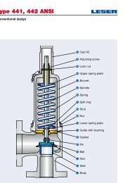
![Stückliste Type 441, 442 DIN [DE] - Leser](https://img.yumpu.com/50352159/1/189x260/stuckliste-type-441-442-din-de-leser.jpg?quality=85)