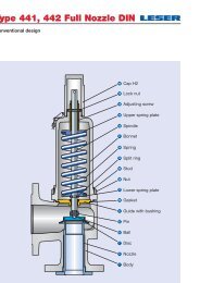
Type 462 HDD Determination of coefficent of discharge in case of lift restriction or back pressure Diagram for evaluation of ratio of lift / flow diameter (h/d 0 ) in reference to the coefficient of discharge (K dr /α w ) h = Lift [mm] d 0 = Flow diameter [mm] of selected safety valve, refer to table article numbers h/d 0 = Ratio of lift / flow diameter p a0 = Back pressure [bar a ] p 0 = Set pressure [bar a ] p a0/p 0 = Ratio of back pressure / set pressure K dr = Coefficient of discharge acc. to DIN EN ISO 4126-1 α w = Coefficient of discharge acc. to AD 2000-Merkblatt A2 K b = Back pressure correction factor acc. to API 520 topic 3.3 d 0 Ø 9 mm d 0 Ø 13 mm 0,85 K dr = α w = f (h/d 0 ) – S/G 0,85 K dr = α w = f (h/d 0 ) – S/G Coefficient of discharge K dr / αw 0,80 Ratio of lift / flow diameter h / d 0 0,24 Ratio of lift / flow diameter h / d 0 0,75 0,75 0,65 0,70 0,55 0,65 0,45 0,60 0,35 0,55 0,50 0,25 0,45 0,15 0,10 0,15 0,20 0,25 0,05 0,1 0,15 Coefficient of discharge K dr / αw 0,19 0,2 d 0 Ø 9 mm d 0 Ø 13 mm 0,65 K dr = α w = f (h/d 0 ) – L 0,60 K dr = α w = f (h/d 0 ) – L 0,60 0,55 Coefficient of discharge K dr / αw Ratio of lift / flow diameter h / d 0 0,24 Ratio of lift / flow diameter h / d 0 0,55 0,55 0,45 0,50 0,40 0,45 0,35 0,30 0,40 0,25 0,35 0,20 0,30 0,15 0,10 0,15 0,20 0,25 0,05 0,1 Coefficient of discharge K dr / αw 0,15 0,19 0,2 Diagram for evaluation of ratio of the coefficient of discharge (K dr /α w ) in reference to the ratio of back pressure / set pressure (p a0 /p 0 ) d 0 Ø 9 mm d 0 Ø 13 mm 0,9 K dr = α w = f (p a0 /p 0 ) and K b = f (p a0 /p 0 ) 0,9 K dr = α w = f (p a0 /p 0 ) and K b = f (p a0 /p 0 ) 1,10 Type 462 HDD Coefficient of discharge K dr / αw 0,8 0,8 1,00 Ratio of back pressure / set pressure p a0 / p 0 0,66 Ratio of back pressure / set pressure p a0 / p 0 0,90 0,7 0,7 0,80 0,6 0,6 0,70 0,5 0,60 0,5 0,4 0,50 0,4 0,40 0,3 0,3 0,30 0,2 0,2 0,20 0,1 0,10 0,1 0,0 0,00 0,0 0,2 0,3 0,4 0,5 0,6 0,7 0,3 0,4 0,5 0,6 0,7 Back pressure correction factor K b Coefficient of discharge K dr / αw 0,8 0,83 1,00 0,90 0,80 0,70 0,60 0,50 0,40 0,30 0,20 0,10 0,00 Back pressure correction factor K b How to use please refer to page 00/08 08/18 LWN 481.01-E
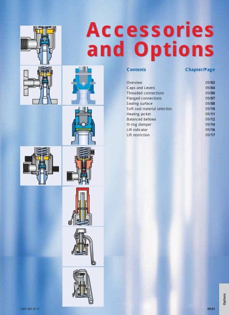
Accessories and Options Contents Chapter/Page Overview 09/02 Caps and Levers 09/04 Threaded connections 09/06 Flanged connections 09/07 Sealing surface 09/08 Soft seal material selection 09/10 Heating jacket 09/11 Balanced bellows 09/12 O-ring damper 09/14 Lift indicator 09/16 Lift restriction 09/17 Options LWN 481.01-E 09/01


![Stückliste Type 441, 442 DIN [DE] - Leser](https://img.yumpu.com/50352159/1/189x260/stuckliste-type-441-442-din-de-leser.jpg?quality=85)