Philips QL Induction Lighting Systems - Philips Lighting
Philips QL Induction Lighting Systems - Philips Lighting
Philips QL Induction Lighting Systems - Philips Lighting
- No tags were found...

You also want an ePaper? Increase the reach of your titles
YUMPU automatically turns print PDFs into web optimized ePapers that Google loves.
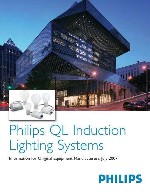
Photo courtesy of Seattle Public Library<br />
<strong>Philips</strong> <strong>QL</strong> <strong>Induction</strong><br />
<strong>Lighting</strong> <strong>Systems</strong><br />
Information for Original Equipment Manufacturers, July 2007
Contents<br />
1. GENERAL INFORMATION ON PHILIPS <strong>QL</strong><br />
INDUCTION LAMP SYSTEMS.................................................3<br />
1.1 INTRODUCTION.....................................................................3<br />
1.2 LAMP SYSTEM TECHNOLOGY AND OPERATION .......................3<br />
1.2.1 Operating principle.....................................................3<br />
1.2.2 Lamp system components............................................4<br />
1.2.3 The lamp .....................................................................4<br />
1.2.4 The power coupler ......................................................4<br />
1.2.5 The HF generator .......................................................5<br />
1.3 NOMENCLATURE ..................................................................5<br />
2. LUMINAIRE DESIGN ............................................................7<br />
2.1 INTRODUCTION.....................................................................7<br />
2.2 POSITIONING OF COMPONENTS ..............................................7<br />
2.3 GROUNDING AND FIXATION ..................................................7<br />
2.4 GENERAL WIRING .................................................................7<br />
2.4.1 Power supply wiring (class I) .....................................8<br />
2.4.2 Power supply wiring (class II) ....................................8<br />
2.4.3 HF output wiring (class I + II) ...................................8<br />
2.4.4 Strain relief .................................................................8<br />
2.5 TEMPERATURE MEASUREMENTS............................................8<br />
2.5.1 General .......................................................................8<br />
2.5.2 Permissible temperatures and lifetime of HF<br />
generator .............................................................................9<br />
2.5.3 Permissible temperatures of power coupler................9<br />
2.5.4 Permissible temperatures of amalgam......................10<br />
2.5.5 Heat sink design........................................................10<br />
2.6 LAMP .................................................................................11<br />
2.6.1 PET value..................................................................11<br />
2.6.2 Damage factor ..........................................................11<br />
2.6.3 Application................................................................11<br />
2.6.4 Lamp holder / lamp base...........................................11<br />
3. GUIDELINES FOR THE INSTALLATION OF <strong>QL</strong><br />
LUMINARIES............................................................................12<br />
3.1 EARTH LEAKAGE CIRCUIT BREAKERS...................................12<br />
3.2 INRUSH CURRENT................................................................12<br />
3.3 TESTING THE INSTALLATION ...............................................12<br />
3.4 AMBIENT LUMINAIRE TEMPERATURES AND OPTIMUM <strong>QL</strong><br />
LAMP SYSTEM LIFETIME ............................................................13<br />
3.5 ON/OFF SWITCHING.............................................................13<br />
4. LAMP OPERATION .............................................................14<br />
4.1 STARTING CHARACTERISTICS..............................................14<br />
4.1.1 Ignition and lifetime performance.............................14<br />
4.1.2 Luminous flux during starting period........................14<br />
4.1.3 Lumen maintenance ..................................................14<br />
4.2 BURNING POSITION .............................................................14<br />
4.3 OPTICAL DESIGN.................................................................14<br />
4.3.1 Relationship of luminous flux, system wattage,<br />
amalgam and ambient temperature ...................................15<br />
4.4 LUMINOUS FLUX VS. TAMBIENT.............................................15<br />
5. <strong>QL</strong> LAMP SYSTEM SPECIFICATIONS ...........................15<br />
5.1 MECHANICAL CHARACTERISTICS ........................................15<br />
5.2 ELECTRICAL CHARACTERISTICS ..........................................17<br />
5.3 LIGHT PERFORMANCE CHARACTERISTICS ............................18<br />
5.3.1 Luminous flux and efficacy .......................................18<br />
5.3.2 Luminous intensity diagrams ....................................19<br />
5.3.3 Color characteristics ................................................22<br />
5.3.4 Effect of supply voltage fluctuations .........................22<br />
6. LIGHTING INSTALLATION AND ENVIRONMENT.....23<br />
6.1 ELECTROMAGNETIC COMPATIBILITY...................................23<br />
6.1.1 RFI (Radio Frequency Interference).........................23<br />
6.1.2 Immunity ...................................................................23<br />
6.2 HUMIDITY..........................................................................23<br />
6.3 INTERFERENCE WITH INFRARED REMOTE CONTROL EQUIPMENT<br />
................................................................................................23<br />
6.4 STANDARDS AND APPROVALS .............................................23<br />
6.5 IP CODES; DUST AND MOISTURE PROTECTION......................24<br />
6.6 DIMMING ...........................................................................24<br />
6.7 LAMP SYSTEM DISPOSAL.....................................................24<br />
6.7.1 The lamp ...................................................................24<br />
6.7.2 The power coupler ....................................................24<br />
6.7.3 The HF generator .....................................................24<br />
7. SERVICE................................................................................25<br />
7.1 GENERAL ...........................................................................25<br />
7.2 LUMINAIRE MEASUREMENT ................................................25<br />
8. DERIVED PRODUCT <strong>QL</strong>-R 85W.......................................26<br />
8.1 SUMMARY..........................................................................26<br />
8.2 DESCRIPTION......................................................................26<br />
8.3 APPLICATIONS....................................................................26<br />
8.4 PHILIPS QUALITY ................................................................26<br />
8.5 COMPLIANCES AND APPROVALS..........................................26<br />
8.6 DIMENSIONS.......................................................................26<br />
8.7 ELECTRICAL CHARACTERISTICS ..........................................27<br />
8.8 LIGHT PERFORMANCE CHARACTERISTICS ............................27<br />
8.9 SPECTRAL POWER DISTRIBUTION.........................................27<br />
8.10 POLAR LIGHT DISTRIBUTION .............................................28<br />
LUMINAIRE MEASUREMENT REQUEST FORM ALL<br />
OVER THE WORLD ..................................................................29<br />
LUMINAIRE MEASUREMENT REQUEST FORM USA....30<br />
<strong>QL</strong> INDUCTION LUMINAIRE DESIGN CHECKLIST.......31<br />
TROUBLESHOOTING GUIDE...............................................32<br />
2<br />
Content provisional. <strong>Philips</strong> <strong>Lighting</strong> B.V. reserves the<br />
right to change data without prior notification.<br />
October 2006. Copyright <strong>Philips</strong> <strong>Lighting</strong> B.V.<br />
All right reserved.<br />
Reproduction in whole or in part is prohibited without<br />
prior permission.
1. General information on <strong>Philips</strong> <strong>QL</strong> induction lamp systems<br />
1.1 Introduction<br />
The <strong>QL</strong> lamp systems use a unique physical principle of light<br />
generation. This lamp system is therefore classified in a new<br />
family of sources, the <strong>QL</strong> induction lamp systems.<br />
<strong>QL</strong> induction lighting is a breakthrough for professional,<br />
general and special lighting applications; not only because of<br />
its high luminous efficacy and excellent light quality, but<br />
especially because of its unprecedented lifetime. System<br />
lifetime is rated at 60,000 hours, or about 15 years (based<br />
on 4000 burning hrs/year) in many applications, with a failure<br />
rate of less than 10%. Average lifetime with 50 % survivals is<br />
rated at 100,000 hrs. With this unmatched durability, <strong>QL</strong><br />
offers substantial savings in direct maintenance costs, as<br />
well in indirect costs. The major features of <strong>QL</strong> lamp<br />
systems, and their related benefits for the user, are:<br />
Features:<br />
Benefits:<br />
1.2 Lamp system technology and<br />
operation<br />
1.2.1 Operating principle<br />
<strong>QL</strong> induction lighting is based on a principle, which is<br />
fundamentally different from that of conventional fluorescent<br />
lamps (e.g. TL-D, TL-5 or PL type lamps).<br />
In conventional fluorescent lamps the electric current is<br />
supplied to the gas discharge through the glowing<br />
electrodes. In <strong>QL</strong> induction lamps the electrical energy is<br />
supplied to the gas discharge by means of a high frequency<br />
electromagnetic field without any electrodes. In conventional<br />
discharge lamps the electrodes mostly are the lifedetermining<br />
factor. Since these electrodes are not present in<br />
<strong>QL</strong> induction lamps, life of <strong>QL</strong> lamps can be very long.<br />
Ferrite<br />
No electrodes or filaments<br />
• ultra long life time of < 10 % failure • high reliability and nearly<br />
rate at 60,000 hrs<br />
maintenance free operation<br />
• low lumen depreciation of < 30 % at • lasting high light output right through<br />
60,000 hrs<br />
lifetime<br />
• low operating temperature of • increased safety: more standard<br />
components<br />
luminaire construction<br />
High frequency operation<br />
• high system efficacy (65-70 lm/W) • economic, environment-friendly<br />
lighting in situations with long<br />
burning hours<br />
• no flickering<br />
• restful- non fatiguing light<br />
• no stroboscopic effect<br />
• no noise<br />
Electronic control<br />
• output protected HF generator<br />
Instant (re-)start<br />
• when needed light always instantly<br />
available<br />
3-line fluorescent coating<br />
• no danger with rotating machinery<br />
• restful and non disturbing in<br />
operation<br />
• automatic switch off in case of<br />
failure of lamp.<br />
• more comfort<br />
• extra energy saving feasible in<br />
combination with presence<br />
detectors<br />
• suitable for security and safety<br />
lighting<br />
• useful light immediately after switch<br />
on<br />
• choice of color temperature<br />
• white light<br />
• good color rendering (Ra>80)<br />
Amalgam controlled Hg-vapor pressure<br />
• constant light output over a wide<br />
range of ambient temperatures<br />
Table 1: Features and benefits of <strong>QL</strong> lamp system<br />
I P<br />
Figure 1: <strong>Induction</strong> principal<br />
H<br />
I S<br />
3
The discharge in the lamp is maintained by means of an<br />
alternating magnetic (induction) field. This is generated by<br />
an antenna (see figure 6) in the centre of the discharge,<br />
therefore without the use of electrodes. The wall of the lamp<br />
is coated on the inside with a fluorescent phosphor mixture,<br />
the well-known 3-line Super /80 phosphors used in TL-D,<br />
TL-5 and PL type lamps. These phosphor mixtures convert<br />
the generated UV light into visible light. Due to the absence<br />
of electrodes, which are the lifetime-limiting components of<br />
conventional fluorescent lamps, the ultra-long life of<br />
induction lamps is ensured.<br />
b ulb<br />
f luorescent layer<br />
Figure 2: Discharge principle in the <strong>QL</strong> lamp bulb<br />
In the <strong>QL</strong> induction lamp system, the energy source –<br />
equivalent to the primary coil in the transformer– is the<br />
lamp’s induction coil, which is powered by high-frequency<br />
electronics. The secondary coil is represented by the lowpressure<br />
gas discharge (see figure 2). The induced current<br />
causes a low-pressure mercury discharge, like in<br />
conventional fluorescent lamps. Similar to other fluorescent<br />
lamps, the ultra violet radiation generated in the discharge is<br />
converted to visible light by the fluorescent phosphor coating<br />
on the inside of the bulb wall.<br />
1.2.2 Lamp system components<br />
The <strong>QL</strong> lamp system consists of three components (see<br />
figure 3), which will be described further in this chapter:<br />
A: The lamp (discharge vessel)<br />
B: The power coupler (construction base with antenna,<br />
mounting flange and electrical connection cable)<br />
C: The HF generator (electronics inclusive housing)<br />
r oom for antenna<br />
stem<br />
a uxiliary amalgam<br />
( 55W only)<br />
main amalgam<br />
l amp cap<br />
Figure 4: The <strong>QL</strong> 55W/85W lamp (165W lamp different<br />
shape)<br />
In the same way as in other compact fluorescent lamps the<br />
light output is maintained over a wide temperature range by<br />
means of an amalgam. This amalgam is located in a<br />
reservoir attached to the discharge vessel (see figure 4).<br />
The lamp is fixed to the bottom part of the power coupler by<br />
means of the unique twist base system (see figure 5).<br />
CLICK<br />
A B C<br />
Figure 3: <strong>QL</strong> lamp system components<br />
1.2.3 The lamp<br />
The <strong>QL</strong> lamp or discharge vessel consists of a glass bulb<br />
(see figure 4) containing an amalgam (mercury metal<br />
mixture) and an inert buffer gas.<br />
Figure 5: Assembly of lamp with power coupler<br />
1.2.4 The power coupler<br />
The power coupler (see figure 6) is the part of the <strong>QL</strong> lamp<br />
system, which transfers the energy from the HF generator to<br />
the discharge in the vessel. It consists of an antenna, a heat<br />
conduction rod with mounting flange and a coaxial<br />
connecting cable, all assembled together on a plastic carrier.<br />
4
The mounting flange should be mounted on a metal heat<br />
sink.<br />
Figure 6: Power coupler<br />
ferrite core<br />
(inside)<br />
coil<br />
heat conducting rod<br />
(inside)<br />
coaxial cable<br />
mounting flange<br />
antenna<br />
1.2.4.1 Antenna<br />
This cylindrical element is the part of the power coupler<br />
located in the centre of the discharge vessel. It includes a<br />
coil and a ferrite core, which produce a high-frequency<br />
magnetic field (2.65 MHz).<br />
The alternating magnetic field provides the energy for the<br />
gas discharge inside the lamp.<br />
1.2.4.2 Heat conducting rod and mounting flange<br />
By means of a conducting rod, which is located inside the<br />
antenna, the heat produced by the coil and the discharge is<br />
removed to the outside via the mounting flange. This metallic<br />
disk has a double function. Firstly, it ensures the mechanical<br />
connection between the lamp and the luminaire, and<br />
secondly it transfers the heat to a heat sink, which must be a<br />
part of the luminaire. The attachment to the luminaire heat<br />
sink is by means of 4 bolts. See section 2.5.5 for proper heat<br />
sink design.<br />
1.2.4.3 Cable<br />
A coaxial cable forms the electrical connection between the<br />
antenna and the HF generator. The cable is permanently<br />
fixed at the antenna side. It can be (dis-)connected at the<br />
side of the HF generator by means of a push-wire connector<br />
in order to facilitate mounting of the lamp system in the<br />
luminaire.<br />
The coaxial cable is made of flexible stranded core<br />
conductors insulated in heat-resistant plastic (125°C/257°F<br />
max.) end provided with a ferrite for EMI reasons. For<br />
optimal performance of the system (light and live) the length<br />
of the cable is fixed (see figure 29)<br />
1.2.5 The HF generator<br />
The HF generator primarily contains an oscillator, which<br />
supplies the high-frequency power to the antenna to initiate<br />
and maintain a gas discharge in the discharge vessel. The<br />
HF generator ensures a well-stabilized oscillator power<br />
supply and filtering of the mains power. In addition, it<br />
provides a very good power factor and a low harmonic<br />
distortion of the mains. All the electronics are housed in a<br />
metal box with a dual function: screening against RFI (Radio<br />
Frequency Interference) and heat conduction to ensure<br />
proper long-life functioning of the electronics. If the metal<br />
housing, and power coupler are properly electrically<br />
connected to ground, the system will comply with all (inter-)<br />
national requirements regarding electromagnetic<br />
compatibility. The HF generator output frequency is<br />
approximately 2.65 MHz.<br />
1.3 Nomenclature<br />
<strong>QL</strong> induction lamp systems:<br />
- Family name of all <strong>QL</strong> lamp systems irrespective of<br />
wattage, supply voltage or color temperature and<br />
operating with low-pressure induction discharge<br />
technology.<br />
<strong>QL</strong> lamp system:<br />
- Combination of a lamp, a power coupler and an HF<br />
generator; all with the same wattage indication.<br />
E.g. <strong>QL</strong> 55W lamp system consists of:<br />
1x Lamp <strong>QL</strong> 55W/8.. Twist base<br />
1x Power Coupler <strong>QL</strong> 55W Twist base<br />
1x HF-Generator <strong>QL</strong> 55W 200-277V<br />
Warning:<br />
- Only system components with the same wattage<br />
indication (55W or 85W or 165W) may be combined!<br />
Any other combination might cause damage to the<br />
lamp system components and possible interference<br />
effects to the environment.<br />
<strong>QL</strong> lamp:<br />
- Lamp <strong>QL</strong>..W/8.. Twist base<br />
Represents a lamp for a specific system wattage<br />
(55W or 85W or 165W) and a certain color<br />
temperature (/827, /830 or /840 for 2700, 3000 and<br />
4000K, respectively).<br />
E.g. Lamp <strong>QL</strong> 85W/830:<br />
Lamp for <strong>QL</strong> 85W lamp system and /830 phosphor<br />
coating (3000K).<br />
The user may not change the length of the cable.<br />
5
<strong>QL</strong>-R lamp:<br />
<strong>QL</strong> lamp with an internal reflective layer.<br />
E.g. Lamp <strong>QL</strong>-R 85W/840:<br />
Lamp for <strong>QL</strong> 85W lamp system and /840 phosphor<br />
coating (4000K) with internal reflective layer.<br />
<strong>QL</strong> power coupler:<br />
- Power Coupler <strong>QL</strong>..W Twist base<br />
Represents a power coupler for a specific system<br />
wattage (55W or 85W or 165W).<br />
E.g. Power Coupler <strong>QL</strong> 55W Twist base:<br />
power coupler for 55W system<br />
<strong>QL</strong> HF generator:<br />
- HF Generator <strong>QL</strong> ..W 200-277V (HV) or HF-<br />
Generator <strong>QL</strong> ..W 100-120V (LV)<br />
Represents a HF generator for a specific system<br />
wattage (55W or 85W or 165W) and supply voltage.<br />
Remark:<br />
- For all <strong>QL</strong> lamp system supply voltages (HV and LV)<br />
the same lamp (55W or 85W or 165W) should be<br />
used.<br />
- For all <strong>QL</strong> lamp system supply voltages (HV and LV)<br />
the same power coupler (55 or 85W or 165W)<br />
should be used.<br />
Warning:<br />
- Every HF generator may only be combined with one<br />
lamp/power coupler set of the same wattage; failure<br />
to observe this basic rule might cause damage to<br />
lamp system components and possible interference<br />
effects to the environment.<br />
6
2. Luminaire design<br />
2.1 Introduction<br />
The design of <strong>QL</strong> luminaire systems related to light<br />
distribution needs the same skills as those for conventional<br />
light sources. Extra attention should be paid to heat and heat<br />
transfer and EMI. In the following paragraphs you can find<br />
more explanations.<br />
2.2 Positioning of components<br />
The <strong>QL</strong> lamp system is constructed in such a way that it<br />
gives designers maximum freedom for positioning the lamp<br />
components in the luminaire, taking into account the<br />
restrictions of the size and the high-frequency operation of<br />
the lamp system itself.<br />
Length of bolts in mounting flange<br />
min (mm)* max (mm)*<br />
<strong>QL</strong> 10 16<br />
Table 2: Wire-length of bolts in the mounting flange<br />
Note*:<br />
this is without the thickness of the heat sink.<br />
Be aware, a too small length of the bolt can<br />
cause lamps to fall down<br />
Advised torque is 2-2.5 Nm (1.5 – 1.8 lbs•ft) (see figure 8).<br />
The coaxial connection cable can be moved through an<br />
angle of 90 degrees with the mounting flange, allowing the<br />
cable to be led directly under the mounting flange through or<br />
along the luminaire heat sink to the generator compartment.<br />
2.3 Grounding and fixation<br />
Unless specially mentioned, it is assumed that the <strong>QL</strong> lamp<br />
system is mounted in a Class I luminaire (provided with an<br />
earth connection point), and that it is electrically well<br />
connected to a metal part of the luminaire. For the HF<br />
generator this is normally done by means of the mounting<br />
bolts with which the ballast and power coupler are mounted<br />
to the earthed mounting plate. Star washers should be used<br />
to ensure a proper ground contact right through the paint or<br />
lacquer covering the luminaire. Bolts to mount the ballast<br />
should be 4 mm diameter. The power coupler must be fixed<br />
to the heat sink by means of its mounting flange. This<br />
mechanical fixation must take place with 4 (!) bolts made of<br />
plated iron or other non-corroding material (preferred is not<br />
to use stainless steel).<br />
The holes in the mounting flange are pre-tapped for M4 bolts<br />
and are positioned in a circle with diameter of 40±1 mm<br />
(1.575"), on two perpendicular axes (see figure 7).<br />
Figure 7: Drill pattern of power coupler mounting flange<br />
(55/85W)<br />
Figure 8: Fixation of power coupler to the heat sink with 4<br />
bolts<br />
2.4 General wiring<br />
The wiring of the <strong>QL</strong> lamp system can be split up into two<br />
parts:<br />
- power supply wiring<br />
- HF output wiring<br />
It is important to observe the following guidelines if optimum<br />
system performance and minimum radio frequency<br />
interference are to be obtained:<br />
- Keep mains wiring away from coaxial cable and<br />
lamps (minimum distance 10 cm).<br />
- If complete separation is not possible, screen the<br />
mains wiring by a grounded metal plate.<br />
- Keep mains wires as short as possible.<br />
- Keep the coaxial cable as close as possible to all<br />
grounded metal parts (maximum distance 2 cm) and<br />
away from the lamp.<br />
- Avoid loops in all wiring.<br />
- Ensure firm electrical contact between all metal<br />
parts and the ballast housing and power coupler.<br />
- The shield of the coaxial cable may not be<br />
grounded.<br />
7
2.4.1 Power supply wiring (class I)<br />
The power supply wiring is the electrical connection between<br />
the power supply and the HF generator input. This wiring<br />
must always use a 3-core cable for phase, neutral and<br />
grounding connections. The phase and neutral of the power<br />
supply must be connected to the connector block as<br />
described on the housing label (see figure 9). In the case of<br />
DC power supply, the +pole must be connected to the phase<br />
connector, and the -pole to the neutral connector.<br />
HF Generator<br />
2.4.3 HF output wiring (class I + II)<br />
This wiring must be via the coaxial cable that is supplied as<br />
standard with the power coupler. Connections to the HF<br />
output of the HF generator must be made according to the<br />
color-coding of wires and the connector block (see table 3<br />
and figure 11). Changing or extending of the coaxial cable is<br />
never allowed.<br />
generator<br />
power coupler<br />
grey (-)<br />
black<br />
orange (+)<br />
red<br />
Table 3: Color-coding of generator and power coupler<br />
L/+ -<br />
N/ -<br />
L/+<br />
N/-<br />
HF Output<br />
Figure 9: Wiring diagram class I luminaires<br />
2.4.2 Power supply wiring (class II)<br />
Under certain conditions it is possible to construct class II<br />
luminaires, in other words luminaires without grounding.<br />
L/+<br />
N/-<br />
HF Generator<br />
HF Output<br />
Black<br />
Red<br />
Warning:<br />
All metal parts connected to the HF generator housing and<br />
mounting flange of the power coupler will be at 50% of the<br />
supplied voltage! The source resistance is high, so that<br />
under normal circumstances there is no danger by touching,<br />
but for safety reasons it is strongly advised to use a doubleinsulated<br />
construction.<br />
The EMI performance will be worse than in class I<br />
designs. In this case EMI testing is recommended to ensure<br />
that the <strong>QL</strong> luminaire complies with the (inter-) national EMC<br />
standards. Extra precautions may be required. The use of<br />
shielded 2-core cable, with shielding only connected to the<br />
HF generator housing, can be beneficial in limiting EMI (see<br />
figure 10).<br />
L/+<br />
N/- N/ -<br />
L/+<br />
HF Generator<br />
Figure 10: Wiring diagram class II luminaires<br />
HF Output<br />
The phase and neutral of the power supply must be<br />
connected to the connector block as described on the<br />
housing label. If a DC power supply is used, the +pole must<br />
be connected to the phase and the -pole to the neutral<br />
connector.<br />
Figure 11: Connecting HF generator and power coupler<br />
2.4.4 Strain relief<br />
The HF generator is not equipped with strain relief, neither<br />
on the power supply side nor on the HF output side. It is<br />
advised to integrate these in the luminaire construction to<br />
prevent (future) contact interruptions, which can cause<br />
possible damage to the <strong>QL</strong> lamp system.<br />
2.5 Temperature measurements<br />
2.5.1 General<br />
In order to achieve optimum operation of the <strong>QL</strong> lamp<br />
system, certain temperature limits should be observed.<br />
Measurements must be made by means of thermocouples,<br />
which must be firmly fixed to the surface. For all<br />
measurements (temperature, light output and power), a<br />
stabilization period of at least two hours must be taken<br />
before any reliable data can be obtained.<br />
The level of stabilization can be checked, by monitoring the<br />
power consumption of the system. If a continuous<br />
measurement has to be made for a range of ambient<br />
temperatures, the rate of temperature change should be less<br />
than 2°C/hour.<br />
For obtaining good light output the <strong>QL</strong> lamps are provided<br />
with an amalgam. This amalgam is located in a short<br />
exhaust tube close to the base of the power coupler.<br />
The temperature of the amalgam determines the mercury<br />
pressure in the vessel. There is a direct relation between<br />
mercury pressure and light output and mercury pressure and<br />
power consumption. The amalgam stabilizes more or less<br />
the mercury pressure in an amalgam temperature range of<br />
70°C/160°F (see figure 12 between point 1 and 2). The<br />
system is designed in such a way that the most optimal<br />
result in light output is reached in case the power<br />
8
consumption is 55W/85W/165W (see point 3 and 4). Good<br />
results (less than 15% deviation in light output) are reached<br />
in case the power consumption is more than 50W for a <strong>QL</strong><br />
55W lamp system, more than 72W for a <strong>QL</strong> 85W lamp<br />
system and more than 145W for a <strong>QL</strong> 165W lamp system.<br />
Luminous flux (lm) (%)<br />
10 0<br />
90<br />
80<br />
70<br />
60<br />
50<br />
40<br />
Figure 12:<br />
Flux<br />
Power<br />
1 4 3 2<br />
Temperat ure (°C)<br />
Typical curve for luminous flux / system power<br />
vs. temperature for an amalgam lamp.<br />
Temperature range between and is<br />
70°C/160°F<br />
2.5.2 Permissible temperatures and lifetime of HF<br />
generator<br />
The maximum temperature inside the luminaire is important<br />
for the lifetime of the HF generator. The relevant parameter<br />
is the case temperature t c on the test point of the HF<br />
generator (see “TEMP TEST POINT tc” on the label of the<br />
HF generator). For all HF generators, the maximum case<br />
temperature is 82°C/179°F. Safe end of life of the generator<br />
cannot be guaranteed above this temperature.<br />
The lifetime of the <strong>QL</strong> lamp system is determined primarily<br />
by the lifetime of the generator, which is 60,000 hours with a<br />
failure rate of 10 % when operated at a t c of 72°C/161°F. If<br />
the temperature t c is below this value of 72°C/161°F, the<br />
lifetime increases.<br />
12 0<br />
110<br />
10 0<br />
90<br />
80<br />
70<br />
60<br />
50<br />
40<br />
System power (%)<br />
Every increase of t c by 10°C/18°F will halve the lifetime of<br />
the HF generator.<br />
For example:<br />
t c = 62°C/143°F, lifetime (=10 % failures) approx. 100,000<br />
hours,<br />
t c max = 82°C/179°F, lifetime (=10 % failures) approx. 25,000<br />
hours,<br />
Exceeding the maximum t c temperature will result in an<br />
undefined reduction of the HF generator lifetime.<br />
Below t c = 62°C/143°F the lifetime of the HF generator will<br />
improve, but not by a factor 2 per 10°C/18°F.<br />
For ignition and operation of the <strong>QL</strong> lamp system, a<br />
temperature of ≥ -25°C/-13°F for the HF generator (test<br />
point) is required.<br />
Tips for HF generator temperature reduction:<br />
1. Do not mount the HF generator too close to the<br />
mounting flange of the power coupler.<br />
2. Ensure good heat transport to the surroundings<br />
(heat sinking).<br />
3. Use separate heat sinks for both the power coupler<br />
and HF generator.<br />
4. Avoid heat radiation from lamp to HF generator.<br />
5. Mount the bottom of the HF generator housing on<br />
its own heat sink; but never apply a heat sink for<br />
the test point only.<br />
6. Create a cooling airflow along the housing, e.g. with<br />
a chimney effect.<br />
2.5.3 Permissible temperatures of power coupler<br />
There is a relation between the amalgam temperature and<br />
the temperature of the base of the power coupler (called<br />
T mounting flange ).<br />
For the <strong>QL</strong> 55W and 165W the advised maximum Tmounting<br />
flange temperature is 100°C/212°F. For the <strong>QL</strong> 85W, the<br />
advised maximum Tmounting flange temperature is 90°C/194°F.<br />
Exceeding the maximum T mounting flange temperature will result<br />
in an undefined reduction of the lamp system lifetime and<br />
lumen output.<br />
The correct way of measuring T mounting flange is at the test point<br />
on the power coupler (see figure 14). The measurements<br />
can be made with a thermocouple.<br />
Figure 13: Typical life expectancy curve at a t c of 72°C/161°F<br />
9
<strong>QL</strong> 55/85W<br />
power coupler<br />
mounting flange<br />
Testpoint<br />
<strong>QL</strong> 165W<br />
power coupler<br />
mounting flange<br />
Testpoint<br />
Figure 14: The location of the mounting flange temperature<br />
testpoint<br />
The thickness (d) of the heat sink is also of major<br />
importance. Assuming that we have different heat sinks with<br />
the same size, but made from different materials, the same<br />
effect in temperature difference will be reached if the<br />
products of thermal conductivity (k) and material thickness<br />
(d) are constant. This means more or less the same result<br />
with a heat sink of 1 mm copper, 2 mm aluminium, 4 mm<br />
brass, 8 mm steel or 26 mm corrosion-resistant steel.<br />
Increasing the surface area of the heat sink will also lead to<br />
improvement, but the effect will be smaller at larger<br />
dimensions and is dependent on the thermal conductivity (k)<br />
of the material and the thickness (d) used (see figure 15).<br />
Recommendation for power coupler temperature reduction:<br />
1. Mount the power coupler on its heat sink with 4<br />
bolts with proper length (see paragraph 2.3).<br />
2. Heat sink materials must have good thermal<br />
conductivity e.g. aluminium (see table 4).<br />
3. Use a material thickness of at least 3 mm for the<br />
heat sink.<br />
4. Use a heat sink with the largest possible surface<br />
area.<br />
5. Painting of the heat sink and metal housing of the<br />
luminaire can reduce the temperature of the power<br />
coupler and the generator.<br />
2.5.4 Permissible temperatures of amalgam<br />
In relatively compactly designed luminaires, used in high<br />
ambient temperatures, the amalgam could melt and drop in<br />
the lamp. The amalgam temperature should therefore not<br />
exceed 105°C/221°F.<br />
2.5.5 Heat sink design<br />
To ensure that the mounting flange of the power coupler<br />
and/or HF generator testpoint temperatures do not exceed<br />
the specified maximum permissible values, additional heat<br />
sinks can be used. The applicable heat transport<br />
mechanisms are conduction in the heat sink to divide the<br />
heat over a bigger surface area, and convection and thermal<br />
radiation to transfer the heat to the surroundings. This<br />
chapter will not indicate exactly how to calculate a heat sink,<br />
but gives some guidelines on how to improve its<br />
performance.<br />
The type of material used for the heat sink has a relatively<br />
great influence on the final result. If we compare, for<br />
instance, the thermal conductivity (k) of copper with that of<br />
corrosion-resistant steel (see table 4), a substantially smaller<br />
heat sink can be made with copper. The most practical<br />
choice to be used for heat sinks is aluminium<br />
Figure 15: The influence of an increasing heat sink diameter<br />
for different k*d for:<br />
A: polished unpainted surface<br />
B: unpainted surface<br />
Material<br />
k (W/mK)<br />
Copper 400<br />
Aluminium 200<br />
Brass 100<br />
Steel 50<br />
Corrosion-resistant steel 15<br />
Table 4: Thermal conductivity (k)<br />
10
Thermal radiation can also form a substantial part of the total<br />
heat transfer, and is of the same order as for convection.<br />
This depends strongly on the emission coefficient of the<br />
surface, which lies between 0 and 1. For example, a<br />
polished aluminium surface has a very low emission<br />
coefficient, while that of a painted surface is very high (see<br />
table 5).<br />
Material Finish<br />
Emission<br />
coefficient<br />
New/polished 0.04 ~ 0.06<br />
Aluminium Oxidized 0.2 ~ 0.3<br />
Anodized 0.8<br />
Paint 0.8 ~ 0.95<br />
Copper<br />
New/polished 0.03 ~ 0.07<br />
Heavy oxidized 0.7 ~ 0.8<br />
Table 5: Emission coefficients<br />
Example:<br />
In table 6 and 7 practical information is given on actual<br />
surface area for two different thicknesses of aluminium, for<br />
the same luminaire in "open" and "closed" conditions. For<br />
both luminaire constructions, the recommended maximum<br />
ambient temperatures are given.<br />
Heat sink (aluminium)<br />
Luminaire<br />
Tambient max<br />
thickness surface area<br />
construction<br />
(mm) (cm 2 ) (°C)<br />
Open 2 75 55<br />
Open 1.5 150 55<br />
Closed 2 75 35<br />
Table 6: Typical heat sink design for power coupler of <strong>QL</strong><br />
55W lamp system<br />
Heat sink (aluminium)<br />
Luminaire<br />
Tambient max<br />
thickness surface area<br />
construction<br />
(mm) (cm 2 ) (°C)<br />
Open 2 250 55<br />
Open 1.5 500 55<br />
Closed 2 250 35<br />
Table 7: Typical heat sink design for power coupler of <strong>QL</strong><br />
85W lamp system<br />
2.6 Lamp<br />
Under normal conditions there are no lifetime-determining<br />
parts in the lamp, which means that it can be fully integrated<br />
in the optical housing system. Only the effectiveness of the<br />
fluorescent coating will decrease over time, but at a much<br />
lower rate than with conventional light sources. The light<br />
output after 60,000 hrs will still be more than 70% of the<br />
initial value. See figure 20<br />
conditions the temperature of the mounting flange of the<br />
power coupler reaches the maximum advised temperature.<br />
The measurable difference depends mainly on the luminaire<br />
heat insulation properties, reflector design and construction<br />
of the luminary heat sink. This may result in a light output<br />
difference of maximum 15% over about 70°C/160°F ambient<br />
temperature variation (see figure 12).<br />
2.6.1 PET value<br />
PET stands for Permissible Exposure Time for human<br />
beings in relation to the amount of radiated UV in hours x<br />
1000 lux.<br />
The amount of UV radiated by <strong>QL</strong> 55W and <strong>QL</strong> 85W lamp<br />
systems is about equal to the amount of UV radiated by<br />
conventional low-pressure mercury lamps per 1000 lm, i.e. ><br />
24h x klx.<br />
This means that <strong>QL</strong> lamp systems comply with the generally<br />
accepted value of 24 hours and can be used in open<br />
luminaires, so without any precautions like filters and front<br />
glasses.<br />
2.6.2 Damage factor<br />
Another effect of UV (and blue light) is the risk of fading of<br />
illuminated goods. The fading impact of a light source can be<br />
expressed by the so-called damage factor (Dfc). The total<br />
effect depends on this factor, the total exposure time and the<br />
illumination level.<br />
The damage factor (Dfc) for <strong>QL</strong> 55W and <strong>QL</strong> 85W lamp<br />
systems is
3. Guidelines for the installation of <strong>QL</strong> luminaries<br />
3.1 Earth leakage circuit breakers<br />
The earth leakage current of the HF generator is normally<br />
less than 0.5 mArms. At the moment of switching-on the<br />
installation, the earth leakage may, however, be temporarily<br />
higher. For this reason it is advised not to connect more than<br />
30 <strong>QL</strong> lamp systems to one 30 mA earth leakage circuit<br />
breaker.<br />
3.2 Inrush current<br />
Like all electronic equipment, <strong>QL</strong> lamp systems have a peak<br />
current shortly after the mains is switched on, the so-called<br />
inrush current (see figure 16).<br />
Notes:<br />
1. It is advised to use C-type MCBs in lighting<br />
installations equipped with electronic ballasts<br />
2. Always make sure that the mains current of the<br />
load does not exceed the nominal permitted value<br />
of the MCB concerned. In fact, it is recommended<br />
that the installation be designed for a maximum<br />
load of 80% of the nominal permitted MCB load.<br />
Maximum number of <strong>QL</strong> lamp systems to be used on one<br />
MCB on account of inrush currents, for 230-277V (HV) and<br />
100-120V (LV) mains voltage.<br />
MCB type <strong>QL</strong> 55W <strong>QL</strong> 85W <strong>QL</strong> 165W<br />
HV LV HV LV HV LV<br />
B type 10A 20 15 20 15 10 5<br />
C type 10A 20 15 20 15 10 5<br />
B type 16A 30 22 30 22 16 8<br />
C type 16A 35 26 35 26 16 8<br />
Table 9: Maximum number of <strong>QL</strong> lamps systems to be used<br />
on one MCB.<br />
Figure 16: Max. duration and value of <strong>QL</strong> lamp system<br />
inrush current.<br />
Note:<br />
If it is absolutely necessary to connect more than<br />
the specified number of <strong>QL</strong> lamp systems to one<br />
MCB, install a relay in the circuitry as shown in<br />
figure 17. This will ensure that the peak current in<br />
the connected <strong>QL</strong> lamp systems does not occur<br />
simultaneously.<br />
Typical values are shown in Table 8.<br />
Inrush current ½ value time at<br />
typical mains impedance<br />
V nom.<br />
(V)<br />
I nom.<br />
(mA)<br />
I max.<br />
(A)<br />
τ<br />
(µs)<br />
<strong>QL</strong> 55W 230 260 12 170<br />
<strong>QL</strong> 55W 120 460 16 170<br />
<strong>QL</strong> 85W 230 400 12 170<br />
<strong>QL</strong> 85W 120 730 16 170<br />
<strong>QL</strong> 165W 230 740 24 140<br />
<strong>QL</strong> 165W 120 1420 28 150<br />
Table 8: Typical inrush currents for <strong>QL</strong> lamp systems<br />
When a number of <strong>QL</strong> lamp systems are operated on Mains<br />
Circuit Breakers (MCBs) and are therefore switched on<br />
simultaneously, the inrush currents have to be taken into<br />
account when calculating the maximum permitted load on<br />
the MCBs. Both B-type and C-type 10A and 16A MCBs have<br />
been considered. The results of these measurements are<br />
reproduced in the tables, stating the recommended<br />
maximum number of <strong>QL</strong> lamp systems to be operated on<br />
one MCB.<br />
Figure 17: Inclusion of a relay in the circuit<br />
3.3 Testing the installation<br />
Testing a <strong>QL</strong> lamp system installation for wire insulation and<br />
electrical strength of the ballast should be carried out with<br />
the luminaries disconnected in order to exclude luminaire<br />
influences (see figure 18 and 19). The earth leakage current<br />
of the ballast will, for example, lead to unreliable<br />
measurements. If, however, in special circumstances the<br />
luminaires must remain connected, the following warnings<br />
should be observed:<br />
1. Testing the insulation of the wiring:<br />
Connect 500V DC between ground and<br />
respectively the phase and the neutral supply<br />
cable.<br />
12
2. Testing the electrical strength of the HF generator:<br />
Connect all <strong>QL</strong> lamp systems inputs together and<br />
connect (1000V + 2U out ) AC for 1 minute between<br />
this point and ground (HF generator housing).<br />
3. Testing between mains and neutral is not permitted,<br />
as this might cause damage to the HF generator.<br />
4. After the test has been completed, make sure that<br />
the neutral is reconnected, since a disconnected<br />
neutral will result in unpredictable mains voltage<br />
(50V..400V), which may damage the HF generator.<br />
L 1<br />
3.4 Ambient luminaire temperatures and<br />
optimum <strong>QL</strong> lamp system lifetime<br />
The heat produced in the luminaire by the HF generator and<br />
lamp must be conducted to the surroundings. When a<br />
luminaire is physically isolated by the ceiling or by isolating<br />
blankets (insulation), the produced heat cannot easily flow to<br />
the surroundings. This will result in the HF generator inside<br />
the luminaire being heated up, which in turn will have an<br />
adverse effect on its life. For an optimum lifetime of the HF<br />
generator it is important to remember that:<br />
- Air should be able to flow freely around the<br />
luminaire<br />
- Air flow through the luminaire reduces the<br />
temperature inside<br />
V 3<br />
230V<br />
V 1<br />
230V<br />
V 2<br />
230V<br />
L 3 L 2<br />
Figure 18: Normal situation in neutral connected<br />
N<br />
3.5 On/off switching<br />
The <strong>QL</strong> lamp system is designed for general lighting<br />
purposes (100,000 cycles). Exceeding this number of<br />
switching cycles could result in a reduction of the HF<br />
generator lifetime. In some applications (flashing, warning<br />
light etc.), frequent on/off switching is needed. A switching<br />
test with 85W 200-277V, 165W 200-277V and 165W 100-<br />
120V generators has been stopped after 7.500.000 switches<br />
without failures.<br />
L 1<br />
V 1=<br />
X<br />
N<br />
V 3= V 2=<br />
L 3 L 2<br />
Figure 19: Situation when neutral is not connected (“loose<br />
neutral”) and the load on all phases is not<br />
symmetrical.<br />
13
4. Lamp operation<br />
4.1 Starting characteristics<br />
4.1.1 Ignition and lifetime performance<br />
<strong>QL</strong> lamp systems offer direct, flicker-free ignition after<br />
switch-on, in both cold and hot conditions.<br />
Ignition time:<br />
< 0.5 s<br />
Hot-restrike time: < 0.5 s<br />
Minimum HF generator test-point temperature for ignition:<br />
-25°C/-13°F.<br />
4.1.2 Luminous flux during starting period<br />
The run-up behavior of <strong>QL</strong> lamp systems is influenced by:<br />
- Luminaire construction.<br />
- Ambient temperature at the moment of ignition.<br />
- The duration of the period that the system was cooldowned<br />
after the last switch-off.<br />
The <strong>QL</strong> lamp systems are based on the low-pressure<br />
mercury discharge technology and therefore in principle<br />
sensitive to (changes in) ambient temperatures. This means<br />
that after switch-on the light output of the lamp will vary until<br />
a stable situation is reached, which depends on the actual<br />
operating conditions. This will not happen in seconds but in<br />
minutes.<br />
If a lamp has reached the stable level and is switched on<br />
again after a short off period, light output will immediately<br />
return to around the normal stable level (incandescent lamplike).<br />
4.1.3 Lumen maintenance<br />
The luminous flux of a <strong>QL</strong> lamp system is expected to have<br />
depreciated after 60,000 hrs to no less than 75% of the initial<br />
flux (see figure 20 for a lumen maintenance curve).<br />
Light (%)<br />
<strong>QL</strong> 85W/840 maintenance<br />
110<br />
105<br />
100<br />
95<br />
90<br />
85<br />
80<br />
75<br />
70<br />
0 10000 20000 30000 40000 50000 60000<br />
Life (h)<br />
Figure 20: Lumen maintenance curve<br />
4.2 Burning position<br />
Although the burning position is universal, the relation<br />
between light output and temperature will be different for<br />
different burning positions. In the base-up position of the <strong>QL</strong><br />
lamp system, the amalgam temperature will be slightly<br />
higher than in the base-down position with the same<br />
environmental conditions. This phenomenon can be used in<br />
luminaire design for specific ambient temperatures. As an<br />
example, the shift of the luminous flux curve for a typical<br />
design is given in figure 21.<br />
Figure 21: Typical influence of burning position on luminous<br />
flux<br />
4.3 Optical design<br />
<strong>QL</strong> lamp systems offer a homogeneous light distribution, and<br />
can be used in a variety of luminaire designs. The choice of<br />
material, shape and dimensions can help ensure optimum<br />
functioning of the lamp (mechanically, thermally and<br />
photometrically). If a lot of light is reflected back to the lamp,<br />
this will increase the lamp operating temperature and may<br />
result in lower light output. The reason for this is that the<br />
main amalgam temperature will increase, which in turn<br />
regulates the light output. For the same reason, it is advised<br />
to keep the lamp cap behind the reflector (if used), because<br />
the main amalgam is located in the lamp cap (see figure 22).<br />
14
Figure 22: Influence of reflector position around lamp with<br />
chimney effect<br />
A space between the reflector and the lamp ("chimney"<br />
effect) increases the main amalgam temperature. In some<br />
cases the main amalgam temperature can become too high,<br />
so that the lamp system’s operating point falls outside the<br />
preferred range.<br />
temperature range. In outdoor luminaires, which may be<br />
used at temperatures below 0°C/32°F, the luminous flux can<br />
be too low. This can be improved by increasing the<br />
temperature of the main amalgam. This can be done in<br />
different ways:<br />
- Position lamp base-up instead of base-down or<br />
horizontal if possible.<br />
- Improve insulation of the total luminaire; care<br />
should be taken in this case that the maximum<br />
permissible temperature of the HF generator<br />
and power coupler-mounting flange is not<br />
exceeded in the practical application.<br />
- Encapsulate the lamp base (partly) in a heatradiating<br />
envelope; this envelope can be a part<br />
of the power coupler heat sink or of the<br />
reflector.<br />
5. <strong>QL</strong> lamp system specifications<br />
5.1 Mechanical characteristics<br />
4.3.1 Relationship of luminous flux, system wattage,<br />
amalgam and ambient temperature<br />
The <strong>QL</strong> lamp is provided with an amalgam. Therefore the<br />
light output and system wattage have a direct relationship to<br />
the amalgam temperature during operation. This means in<br />
practice that the actual luminous flux and system wattage<br />
depend on the luminaire construction, its heat insulation<br />
properties and the ambient temperature, which determine<br />
the actual amalgam temperature. For a typical <strong>QL</strong> lamp<br />
system the relationship between luminous flux and system<br />
wattage vs. temperature is shown in figure 23. See also the<br />
remarks about the amalgam temperature made in chapter<br />
2.5.4.<br />
Figure 24: Power coupler dimensions<br />
Figure 23: Typical <strong>QL</strong> 85W lamp system curves for luminous<br />
flux / system power vs. temperature<br />
4.4 Luminous flux vs. Tambient<br />
The temperature of the main amalgam normally controls the<br />
luminous flux of <strong>QL</strong> lamp systems. Therefore it will be more<br />
or less constant (deviation max. 15%) over a wide<br />
Power coupler type <strong>QL</strong> 55W <strong>QL</strong> 85W <strong>QL</strong> 165W<br />
A nom (mm / inch) 56 / 2.20 56 / 2.20 56 / 2.20<br />
B nom (mm / inch) 40 / 1.58 40 / 1.58 40 / 1.58<br />
C nom (mm / inch) 133.5 / 5.26 164.5 / 6.48 185 / 7.28<br />
D nom (mm / inch) 27 / 1.06 27 / 1.06 27 / 1.06<br />
E nom (mm / inch) 555 / 21.85 555 / 21.85 555 / 21.85<br />
F max (mm / inch) 9.5 / 3.74 9.5 / 3.74 9.5 / 3.74<br />
Table 10: Power coupler dimensions<br />
15
The length and thickness of the coaxial cable of the power<br />
couplers have been changed in 2005. Table 11 shows the<br />
changes.<br />
Power<br />
coupler dimension old current<br />
type<br />
<strong>QL</strong> 55W<br />
E nom (mm) 450 ± 20 555 ± 20<br />
F max (mm) 5.5 9.5<br />
<strong>QL</strong> 85W<br />
E nom (mm) 450 ± 20 555 ± 20<br />
F nom (mm) 5.5 9.5<br />
<strong>QL</strong> 165W<br />
E nom (mm) 430 ± 20 555 ± 20<br />
F nom (mm) 9.5 9.5<br />
Table 11: The length and thickness changes of the coaxial<br />
cable.<br />
HF generator type <strong>QL</strong> 55W <strong>QL</strong> 85W <strong>QL</strong> 165W<br />
A nom (mm / inch) 40.8 / 1.61 40.8 / 1.61 42.3 / 1.67<br />
B nom (mm / inch) 78.0 / 3.07 78.0 / 3.07 118 / 4.65<br />
C nom (mm / inch) 4.5 / 0.18 4.5 / 0.18 4.5 / 0.18<br />
D nom (mm / inch) 60 / 2.36 60 / 2.36 70 / 2.76<br />
E nom (mm / inch) 150 / 5.91 150 / 5.91 190 / 7.48<br />
F nom (mm / inch) 140 / 5.51 140 / 5.51 178 / 7.01<br />
G nom (mm / inch) 127.3 / 5.01 127.3 / 5.01 148.7 / 5.85<br />
Table 12: HF generator dimensions<br />
E<br />
F<br />
G<br />
D<br />
C<br />
Figure 26: Lamp dimensions<br />
A<br />
Figure 25: HF generator dimensions<br />
B<br />
Lamp type <strong>QL</strong> 55W <strong>QL</strong> 85W <strong>QL</strong> 165W<br />
A max (mm / inch) 141 / 5.55 180.5 / 7.11 205.5 / 8.09<br />
B max (mm / inch) 86 / 3.39 111 / 4.37 131 / 5.16<br />
C max (mm / inch) 57 / 2.24 57 / 2.24 57 / 2.24<br />
D max (mm / inch) 49 / 1.93 49 / 1.93 49 / 1.93<br />
Table 13: Lamp dimensions<br />
Weights (g) <strong>QL</strong> 55W <strong>QL</strong> 85W <strong>QL</strong> 165W<br />
Lamp 120 135 205<br />
Power coupler 185 220 290<br />
Generator 590 620 705<br />
Total <strong>QL</strong> lamp system 895 975 1205<br />
Table 14: Weights.<br />
16
5.2 Electrical characteristics<br />
There is a relation between the system power and the amalgam temperature (see chapter 4.3.1). In table 15 the values of the<br />
system power are given if the amalgam temperature is between 50°C and 105°C (for 165W between 70°C and 105°C). This is in<br />
stable situation. In practice this means about two hours after ignition. During the run-up the values can deviate.<br />
<strong>QL</strong> 55W<br />
100-120V<br />
<strong>QL</strong> 55W<br />
200-277V<br />
<strong>QL</strong> 85W<br />
100-120V<br />
<strong>QL</strong> 85W<br />
200-277V<br />
<strong>QL</strong> 165W<br />
100-120V<br />
System power* ) nom. W 55 85 165<br />
System power* ) min. W 51 71 160<br />
System power* ) max. W 57 89 190<br />
* ) At design voltage; 115V and 230V respectively<br />
Table 15: System power in stable burning situation.<br />
<strong>QL</strong> 165W<br />
200-277V<br />
More electrical characteristics:<br />
<strong>QL</strong> 55W<br />
100-120V<br />
<strong>QL</strong> 55W<br />
200-277V<br />
<strong>QL</strong> 85W<br />
100-120V<br />
<strong>QL</strong> 85W<br />
200-277V<br />
<strong>QL</strong> 165W<br />
100-120V<br />
<strong>QL</strong> 165W<br />
200-277V<br />
AC supply voltage nom. V 120 230 120 230 120 230<br />
AC supply voltage min. V 90 180 90 180 90 180<br />
AC supply voltage max. V 140 305 140 305 140 305<br />
DC supply voltage nom. V 120 230 120 230 120 230<br />
DC supply voltage min. V 90 180 90 180 90 180<br />
DC supply voltage max. V 180 350 180 350 180 350<br />
Supply frequency nom. Hz 60 50 60 50 60 50<br />
Supply frequency min. Hz 47 47 47 47 47 47<br />
Supply frequency max. Hz 63 63 63 63 63 63<br />
Supply current nom. mA 460 260 730 400 1420 740<br />
Inrush current max. A 16 12 16 12 28 24<br />
Duration inrush current max. µs 170 170 170 170 150 140<br />
Power factor nom. >0.92 >0.92 >0.92 >0.92 >0.92 >0.92<br />
HF output frequency nom. MHz 2.65 2.65 2.65 2.65 2.65 2.65<br />
HF output frequency min. MHz 2.30 2.30 2.30 2.30 2.30 2.30<br />
HF output frequency max. MHz 3.00 3.00 3.00 3.00 3.00 3.00<br />
HF output voltage max. kV 1.5 1.5 1.5 1.5 1.5 1.5<br />
Leakage current mA
5.3 Light performance characteristics<br />
5.3.1 Luminous flux and efficacy<br />
Values at 100 h. <strong>QL</strong> 55W <strong>QL</strong> 85W <strong>QL</strong> 165W<br />
Color characteristic /827/830/840 /827/830/840 /827/830/840<br />
Luminous flux nom. lm 3500 6000 12000<br />
Luminous flux min. lm 3200 5500 11000<br />
Luminous flux max. lm 3800 6500 12500<br />
System efficacy nom. lm/W 63.5 70 72.5<br />
Table 17: Luminous flux and efficacy<br />
18
5.3.2 Luminous intensity diagrams<br />
Average lumen<br />
gamma<br />
intensity<br />
(degree)<br />
(cd/1000lm)<br />
0 66.1<br />
5 67.6<br />
10 69.1<br />
15 71.2<br />
20 73.3<br />
25 75.6<br />
30 78.1<br />
35 80.6<br />
40 82.9<br />
45 84.7<br />
50 86.0<br />
55 87.0<br />
60 88.1<br />
65 89.3<br />
70 90.1<br />
75 90.7<br />
80 91.1<br />
85 91.1<br />
90 91.0<br />
95 90.4<br />
100 89.0<br />
105 87.2<br />
110 85.0<br />
115 82.3<br />
120 79.1<br />
125 75.6<br />
130 71.6<br />
135 67.2<br />
140 62.3<br />
145 57.1<br />
150 51.8<br />
155 46.6<br />
160 41.0<br />
165 32.6<br />
170 23.1<br />
175 0.5<br />
180 0.5<br />
Table 18: Luminous intensity <strong>QL</strong>55W<br />
Figure 27: Light distribution <strong>QL</strong> 55W<br />
Figure 28: Azimuth angle <strong>QL</strong>55W<br />
See figures 27 and 28<br />
19
Average lumen<br />
gamma<br />
intensity<br />
(degree)<br />
(cd/1000lm)<br />
0 75.8<br />
5 75.8<br />
10 76.0<br />
15 76.2<br />
20 76.4<br />
25 76.9<br />
30 77.7<br />
35 78.9<br />
40 80.4<br />
45 82.2<br />
50 84.3<br />
55 86.1<br />
60 87.8<br />
65 89.2<br />
70 90.3<br />
75 91.1<br />
80 91.6<br />
85 91.5<br />
90 91.0<br />
95 90.0<br />
100 88.4<br />
105 86.5<br />
110 84.0<br />
115 81.1<br />
120 77.9<br />
125 74.3<br />
130 70.5<br />
135 66.4<br />
140 62.2<br />
145 57.9<br />
150 53.7<br />
155 49.5<br />
160 45.4<br />
165 40.9<br />
170 28.6<br />
175 0.3<br />
180 0.3<br />
Table 19: Luminous intensity <strong>QL</strong> 85W<br />
Figure 29: Light distribution <strong>QL</strong> 85W<br />
Figure 30: Azimuth angle <strong>QL</strong> 85W<br />
See figures 29 and 30<br />
20
Average lumen<br />
gamma<br />
intensity<br />
(degree)<br />
(cd/1000lm)<br />
0 65.5<br />
5 65.6<br />
10 65.7<br />
15 66.1<br />
20 66.6<br />
25 67.3<br />
30 68.3<br />
35 69.8<br />
40 71.7<br />
45 74.1<br />
50 76.8<br />
55 79.5<br />
60 82.3<br />
65 84.9<br />
70 87.2<br />
75 89.0<br />
80 90.3<br />
85 91.1<br />
90 91.5<br />
95 91.4<br />
100 90.9<br />
105 89.8<br />
110 88.3<br />
115 86.3<br />
120 83.8<br />
125 80.8<br />
130 77.5<br />
135 73.8<br />
140 69.9<br />
145 65.9<br />
150 62.0<br />
155 59.4<br />
160 54.0<br />
165 49.1<br />
170 37.9<br />
175 3.54<br />
180 0.22<br />
Table 20: Luminous intensity <strong>QL</strong> 165W<br />
Figure 31: Light distribution <strong>QL</strong> 165W<br />
Figure 32: Azimuth angle <strong>QL</strong> 1685W<br />
See figures 31 and 32<br />
21
5.3.3 Color characteristics<br />
Table 21 presents the color characteristics of <strong>QL</strong> lamps at<br />
100 hours.<br />
5.3.4.3 Typical spectral power distributions<br />
<strong>QL</strong> 55W /827 /830 /840<br />
Color rendering index CRI Ra >80 >80 >80<br />
Chromaticity coordinate x 0.471 0.442 0.392<br />
Chromaticity coordinate y 0.416 0.404 0.385<br />
SDCM max. SDCM 5 5 5<br />
P.E.T. (NIOSH) h*klx >24 >24 >24<br />
Damage factor Dfc 80<br />
Chromaticity coordinate x 0.476 0.444 0.392<br />
Chromaticity coordinate y 0.417 0.404 0.385<br />
SDCM max. SDCM 5 5 5<br />
P.E.T. (NIOSH) h*klx >24 >24 >24<br />
Damage factor Dfc 80<br />
Chromaticity coordinate x 0.472 0.435 0.388<br />
Chromaticity coordinate y 0.418 0.398 0.380<br />
SDCM max. SDCM 5 5 5<br />
P.E.T. (NIOSH) h*klx >24 >24 >24<br />
Damage factor Dfc
6. <strong>Lighting</strong> installation and environment<br />
6.1 Electromagnetic compatibility<br />
Electromagnetic compatibility, EMC, is the ability of a device<br />
or system to operate satisfactorily in its electromagnetic<br />
environment, without causing unacceptable interference in<br />
practical situations. <strong>Philips</strong> <strong>QL</strong> lamp systems fulfill the<br />
requirements with regard to electromagnetic compatibility as<br />
laid down in European Norms EN 55015, EN 61000-3-2 and<br />
EN 61547.<br />
6.1.1 RFI (Radio Frequency Interference)<br />
The Radio Frequency Interference (RFI) regulations as laid<br />
down in EN 55015 concern the frequency range between 9<br />
and 30kHz. However, nowadays more and more electronic<br />
products are being marketed for operation on higher<br />
frequencies. The RFI requirements for this kind of equipment<br />
are laid down in the more stringent standard EN 55022, valid<br />
for frequencies up to 1000MHz. <strong>Philips</strong> <strong>QL</strong> lamp systems<br />
fulfill the requirements of this latter standard and are<br />
therefore the best choice if they are to operate in<br />
environments in which other equipment is used working at<br />
frequencies of up to 1000MHz.<br />
6.1.2 Immunity<br />
When the mains voltage deviates from its normal value by<br />
more than the tolerance permits (nominal voltage ±10%),<br />
adverse effects on lamp life, HF generator life and light<br />
output can be expected. Excessively high voltages (U mains<br />
e.g. >350V) over a considerable period of time (>48 hours)<br />
will damage the HF generator. Mains transients and dips, on<br />
the other hand, will not harm the HF generator, provided<br />
they are within the regulations of EN 61547.<br />
6.2 Humidity<br />
<strong>Philips</strong> <strong>QL</strong> lamp systems have been tested for sensitivity to<br />
humid conditions and have proved to be able to resist a<br />
relative air humidity of up to 95%.<br />
- Direct water ingress will damage the <strong>QL</strong> lamp<br />
system.<br />
- Make sure that there can be no condensation on or<br />
in the HF generator and power coupler.<br />
- The HF generator should be so mounted that no<br />
condensation or water from other sources can flow<br />
over or into the HF generator and power coupler.<br />
6.3 Interference with infrared remote<br />
control equipment<br />
Video and audio equipment, computers and also lighting<br />
installations nowadays are often operated by infrared remote<br />
control. The frequency of such infrared signals is in order of<br />
36 kHz. To avoid any interference with this kind of<br />
equipment, the operating frequency of all <strong>Philips</strong> <strong>QL</strong> lamp<br />
systems has been chosen to prevent any problems in the 36<br />
kHz frequency range.<br />
6.4 Standards and approvals<br />
<strong>Philips</strong> <strong>QL</strong> lamp systems comply with all relevant<br />
international rules and regulations, including:<br />
Safety EN 61199<br />
Performance EN 60929<br />
Quality standard ISO 9001<br />
Environmental<br />
ISO 14001<br />
management system<br />
Interference LF<br />
Mains current distortion<br />
THD<br />
EN 61000-3-2 (200-277V)<br />
ANSI C82.11-2002 (200-277V)<br />
Interference HF, measured with BU KGH085, equipped<br />
with one metal spacer between generator and power<br />
coupler plane, without metal gauze.<br />
Conducted EN 55015 (limit 56/46dB at 2.5-<br />
3.0MHz) & FCC class B, CFR 47<br />
part 18<br />
Radiated 30MHz<br />
Electro Magnetic Immunity<br />
Radiated radio frequency<br />
electro magnetic fields.<br />
Test level 10V/m Sine<br />
Wave 80%AM@1kHz<br />
Conducted disturbances<br />
induced by RF fields Test<br />
level 10Vrms Sine Wave<br />
80%AM@1kHz<br />
Power frequency<br />
magnetic fields<br />
Fast transients at max<br />
case temperature 2x2<br />
minutes (Also under no<br />
load condition)<br />
EN 55015 & FCC class B, CFR<br />
47 part 18<br />
EN 55022 class B & FCC class<br />
B, CFR 47 part 18<br />
Performance criteria A of EN<br />
61547.<br />
EN 61000-4-3 80MHz-1GHz<br />
EN 61000-4-6 150kHz-80MHz<br />
EN 61547 clause 5.4<br />
EN 61000-4-4, test level 4, limit<br />
4kV/2.5kHz<br />
23
Surge test at max case<br />
temperature. 4x5 pulses.<br />
Light flicker max 3<br />
seconds is allowed above<br />
1kV surges.<br />
Mains Voltage Dips. To be<br />
tested at max case temp.<br />
Mains Voltage Interrupt.<br />
To be tested at max case<br />
temp.<br />
ESD discharge test:<br />
Contact and air discharge.<br />
Mains transient<br />
EN 61000-4-5 test level 4,<br />
requirement 4kV Line to Earth,<br />
2kV Line to Line<br />
EN 61000-4-11 70% of rated<br />
mains, 200ms<br />
EN 61000-4-11 0% of rated<br />
mains, 5ms. Execute test with<br />
pos. and neg. half cycle.<br />
EN 61547 clause 5.2<br />
ANSI/IEEE C62.41, 7 strikes<br />
Ringing Wave 100kHz, minimum<br />
2.5kV TBD<br />
Safety K123-1<br />
EN61347-2-3<br />
UL935<br />
Approbations<br />
CE, UL, CSA,<br />
KEMA (HV)<br />
Environmental conditions<br />
Humidity IEC 60068-2-30-Db 40°C 21<br />
days cyclic operative 2hrs on, 10<br />
hrs off. In conformity with UN-<br />
D1639-1 table2.3.5, "protected<br />
outdoor use": 10-95%RH.<br />
Vibration<br />
Bumps<br />
Shock test<br />
IEC 60068-2-6-Fc Frequency<br />
range 10-150Hz, Frequency<br />
change 1 oct/min<br />
Acceleration/amplitude<br />
2G/0.15mm peak, 3 directions,<br />
test time 40 min per direction.<br />
IEC 60068-2-29-Eb Acceleration<br />
10G Number of bumps 1000<br />
/16ms 3 directions.<br />
IEC 60068-2-27 40G / 11ms<br />
(semi sinusoidal), 3 directions, 5<br />
shocks per direction.<br />
The <strong>Philips</strong> <strong>QL</strong> lamp system carries the CE marking on basis<br />
of fulfillment of the following standards: EN 61547, EN<br />
61000-3-2 and EN 55015 (as tested in a <strong>Philips</strong> reference<br />
luminaire).<br />
6.5 IP codes; dust and moisture protection<br />
The <strong>QL</strong> lamp system is designed for built-in purposes in<br />
appropriate luminaires. Next to effective temperature control,<br />
the luminaire must also provide dust and moisture<br />
protection, especially for the HF generator part and the<br />
power coupler. Direct water intrusion or a high humidity<br />
causing condensation inside the HF generator and power<br />
coupler should be prevented, as should heavy dust<br />
accumulation. In practice, this means that <strong>QL</strong> luminaires<br />
applied in outdoor applications should be at least classified<br />
as IP 54.<br />
The HF generators for the <strong>QL</strong> 55W, 85W and 165W lamp<br />
systems are classified as IP 40.<br />
6.6 Dimming<br />
At present <strong>QL</strong> lamp systems are not available with dimming<br />
facilities.<br />
6.7 Lamp system disposal<br />
At the end of their (economic) life, appropriate disposal of <strong>QL</strong><br />
lamp systems or their components is recommended.<br />
6.7.1 The lamp<br />
Although only a very small mercury dose is used, it is still<br />
recommended to treat the lamp system part as small<br />
chemical waste. The <strong>QL</strong> lamp can very well be recycled<br />
together with other low-pressure mercury discharge lamps.<br />
Follow local regulations for disposal of this type of light<br />
source.<br />
6.7.2 The power coupler<br />
Due to the fact that no materials are used in the construction<br />
of this part, which at present are known to be harmful to the<br />
environment, this part can be disposed of as normal waste.<br />
Disassembling is relatively easy, so recycling of materials is<br />
also possible.<br />
6.7.3 The HF generator<br />
This component is a RoHS compliant electronic device,<br />
which can be disposed of with normal care. It is<br />
recommended to dispose of this part as normal electronic<br />
waste, according to local regulations.<br />
Temperature shock<br />
IEC 60068-2-14-Na 5 cycles<br />
-40°C/+80°C 30 min 2 chamber<br />
method cycle.<br />
IEC 60068-2-14-Nb -20°C/100°C<br />
2000 cycles. (TBF)<br />
24
7. Service<br />
7.1 General<br />
Although <strong>QL</strong> lamp systems can be regarded as "light<br />
sources for life" because of their specified lifetime of 60,000<br />
hours, it may nevertheless occur that parts of the system fail<br />
before this period is reached, due to internal or external<br />
influences. This does not mean that the total system has to<br />
be replaced but, depending on the failure, only a part of it.<br />
Failures that can occur are:<br />
a) breakage of lamp caused by external influences<br />
b) no light generation after switch-on or failure during<br />
operation<br />
7.2 Luminaire measurement<br />
As extra service we offer a free of charge luminaire<br />
measurement. The temperature household of the fixture is<br />
compared with the requirements and if needed<br />
recommendations for improvement will be given. To make<br />
use of this service fill in the ‘Luminaire measurement request<br />
form’ (see page 29/30 and send it to us by e-mail).<br />
In case a) the (broken) lamp can easily be replaced by a<br />
new one in color /827, /830 or /840. After removing the<br />
remaining parts of the vessel from the power coupler (see<br />
figure 37), a new lamp can be installed by the unique twist<br />
base system to the bottom part of the power coupler (see<br />
figure 5).<br />
Figure 36: Release of lamp from power coupler<br />
In case b) it will in most cases mean that the HF generator<br />
has failed, although there is also the possibility that the lamp<br />
has developed a leak or a contact breakage has occurred<br />
somewhere in the power coupler or the system wiring.<br />
Faultfinding should start by first checking the wiring. If the<br />
wiring is correct, a new one with the same specifications can<br />
replace the HF generator. Then a try-out can be made with a<br />
new lamp, and finally a replacement of the power coupler.<br />
Instructions on (dis-)assembly can be found on the<br />
enclosure packed with the new component.<br />
Servicing must always be done with the <strong>QL</strong> lamp system<br />
disconnected from the supply voltage. Protective glasses<br />
should always be worn!<br />
25
8. Derived product <strong>QL</strong>-R 85W<br />
8.1 Summary<br />
The <strong>QL</strong>-R is a new <strong>QL</strong> induction lamp with internal<br />
reflector. Most of the light is emitted in the forward<br />
direction. This lamp is very suitable for applications<br />
where light in a certain direction is needed and for very<br />
small luminaries where extensive mirrors are not<br />
possible.<br />
As supplier of the <strong>QL</strong> lamp system, <strong>Philips</strong> ensures that,<br />
from the earliest development stage, optimum lamp/ HF<br />
generator performance is maintained.<br />
• International standards.<br />
<strong>Philips</strong> <strong>QL</strong> lamp systems comply with all relevant<br />
international rules and regulations.<br />
8.5 Compliances and approvals<br />
• RFI < 30MHz EN 55015<br />
• RFI > 30MHz EN 55022<br />
• Harmonics EN 61000-3-2<br />
• Immunity EN 61547<br />
• Safety EN 61347<br />
EN 60928<br />
• Performance EN 60929<br />
• Vibration & bump tests IEC 68-2-6-Fc<br />
IEC 68-2-29-Eb<br />
• Quality standards ISO 9001<br />
• Environmental standard ISO 14001<br />
• Approval marks:<br />
Figure 37: <strong>QL</strong>-R lamp system<br />
8.6 Dimensions<br />
8.2 Description<br />
• Ultra-long life up to 15 years based on 4000<br />
burning hours / year<br />
• Low energy consumption<br />
• Constant light, independent of mains voltage<br />
fluctuations<br />
• Automatic stop circuit is activated within 5 seconds<br />
in case of lamp failure (safety stop)<br />
• Flicker-free start, ideal for areas with high<br />
switching frequency<br />
8.3 Applications<br />
Typical areas of application include:<br />
• Indoor, general lighting. Especially for places with<br />
much traffic from passengers like arrival halls in<br />
airports, railway stations and also parking garages.<br />
• Industry, petrochemical industry, offshore. <strong>QL</strong> is<br />
often used in explosion-proof luminaries.<br />
• Cold-storage rooms<br />
• City lighting<br />
• Illumination of roadway signs and advertisement<br />
boards.<br />
8.4 <strong>Philips</strong> quality<br />
This implies optimum quality regarding:<br />
• Ultra-long life.<br />
Figure 38: <strong>QL</strong>-R dimensions<br />
Lamp type <strong>QL</strong>-R 85W<br />
A max (mm / inch) 205.5 / 8.09<br />
B max (mm / inch) 131 / 5.16<br />
C max (mm / inch) 57 / 2.24<br />
D max (mm / inch) 49 / 1.93<br />
E (mm/inch) 50 / 1.97<br />
Table 22: <strong>QL</strong>-R dimensions<br />
26
8.7 Electrical characteristics<br />
There is a relation between the system power and the<br />
amalgam temperature (see chapter 4.3.1). In table 15 the<br />
values of the system power are given if the amalgam<br />
temperature is between 50 and 105 ºC. This is in stable<br />
situation. In practice this means about two hours after<br />
ignition. During the run-up the values can deviate.<br />
<strong>QL</strong>-R 85W<br />
100-120V<br />
<strong>QL</strong>-R 85W<br />
200-277V<br />
System power* ) nom. W 89 88<br />
System power* ) min. W 85 84<br />
System power* ) max. W 93 92<br />
* ) At design voltage; 115V and 230V respectively<br />
Table 23: System power in stable burning situation.<br />
8.8 Light performance characteristics<br />
<strong>QL</strong><br />
lamp<br />
system<br />
Lamp<br />
Efficacy Lumen Color<br />
rendering<br />
index<br />
W lm/W lm %<br />
85 70 6000 80 75<br />
System<br />
power<br />
<strong>QL</strong>-R<br />
85W *)<br />
*) 100-120V or 200-277V<br />
Table 25: Luminous flux and efficacy<br />
8.9 Spectral power distribution<br />
<strong>QL</strong>-R 85W/840<br />
Lumen<br />
maintenance<br />
60,000hrs<br />
More electrical characteristics:<br />
<strong>QL</strong>-R<br />
85W<br />
100-<br />
120V<br />
<strong>QL</strong>-R<br />
85W<br />
200-<br />
277V<br />
AC supply voltage nom. V 120 230<br />
AC supply voltage min. V 90 180<br />
AC supply voltage max. V 140 305<br />
DC supply voltage nom. V 120 230<br />
DC supply voltage min. V 90 180<br />
DC supply voltage max. V 180 350<br />
Supply frequency nom. Hz 60 50<br />
Supply frequency min. Hz 47 47<br />
Supply frequency max. Hz 63 63<br />
Supply current nom. mA 730 400<br />
Inrush current max. A 16 12<br />
Duration inrush current max. µs 170 170<br />
Power factor nom. >0.92 >0.92<br />
HF output frequency nom. MHz 2.65 2.65<br />
HF output frequency min. MHz 2.30 2.30<br />
HF output frequency max. MHz 3.00 3.00<br />
HF output voltage max. kV 1.5 1.5<br />
Leakage current mA
Derived product <strong>QL</strong>-R 85W<br />
8.10 Polar light distribution<br />
150°<br />
150<br />
180°<br />
150°<br />
210°<br />
100<br />
180°<br />
150°<br />
120°<br />
100<br />
50<br />
120°<br />
240°<br />
50<br />
120°<br />
90°<br />
0<br />
90°<br />
270°<br />
0<br />
90°<br />
60°<br />
(Cd/1000lm)<br />
50<br />
100<br />
150<br />
0°<br />
γ<br />
60°<br />
280°<br />
(Cd/1000lm)<br />
50<br />
100<br />
0°<br />
γ<br />
60°<br />
C = 0° + C = 180°<br />
C = 90° + C = 270°<br />
γ = 90°<br />
Fig 40: Polar light distribution<br />
28
Luminaire measurement request form all over the world<br />
(see also the special version for USA-customers)<br />
For every <strong>QL</strong> luminaire to be measured please fill in this form and mail to<br />
info<strong>QL</strong>@philips.com<br />
Name of Customer: ........................................................................................................<br />
Contact Person customer: .............................................................................................<br />
Contact Person <strong>Philips</strong> <strong>Lighting</strong>: ....................................................................................<br />
Place (City/Country): ......................................................................................................<br />
Luminaire Type & Name: ...............................................................................................<br />
V.A.T. nr. (Europe only): ................................................................................................<br />
Information on <strong>QL</strong> luminaire application conditions:<br />
Short description of place where <strong>QL</strong> luminaire is/should be used: .................................<br />
........................................................................................................................................<br />
........................................................................................................................................<br />
........................................................................................................................................<br />
Ambient temperature range: ..........................................................................................<br />
Quantities involved in the project: ..................................................................................<br />
Comments:......................................................................................................................<br />
........................................................................................................................................<br />
........................................................................................................................................<br />
Please put a copy of your request in the packaging of the luminaire.<br />
If available, please send us a picture of your <strong>QL</strong> luminaire by e-mail.<br />
You will get a shipping address and a time-schedule of the measurements as soon as possible.<br />
29
<strong>QL</strong> Fixture Evaluation Request Form for North America<br />
All Fixture evaluations must be coordinated through your <strong>Philips</strong> Sales Representative.<br />
Please fill in this form for each <strong>QL</strong> fixture sent for evaluation. Once you and the <strong>Philips</strong> Sales Rep<br />
have completed the form it can be sent in with the fixture, and/or forwarded to:<br />
andy.mayo@philips.com.<br />
Manufacturer<br />
Name:<br />
Date:<br />
Address<br />
Street:<br />
City: State: Country:<br />
Phone Number:<br />
Manufacturer Contact:<br />
email:<br />
<strong>Philips</strong> <strong>Lighting</strong> Contact:<br />
Fixture<br />
Type:<br />
Model Number:<br />
Project Name:<br />
Estimated Quantities:<br />
Purpose of Evaluation:<br />
OEM Test Results:<br />
Pwr: W Amb: °C PC: °C Gen: °C Amalgam: °C<br />
Is fixture to be returned to the Manufacturer<br />
Please briefly describe how/where the fixture will be used (examples: indoor/outdoor,<br />
geographical location…):<br />
<strong>QL</strong> System Used<br />
Power:<br />
Voltage:<br />
Ambient Temperature<br />
Minimum: °C Maximum: °C<br />
Comments:<br />
Please e-mail pictures and specifications of the fixture if available. A test report will be<br />
provided upon completion of the evaluation.<br />
Ship Fixtures to: <strong>Philips</strong> <strong>Lighting</strong> Company<br />
Attention: Andy Mayo<br />
7265 Route 54 (607) 776-3311<br />
Bath, NY 14810
<strong>QL</strong> <strong>Induction</strong> Luminaire Design Checklist<br />
Lamp (Discharge Vessel) & Power Coupler<br />
Lamp and power coupler are firmly attached to a heat sink plate with 4 bolts with a prescribed diameter,<br />
length & material (<strong>QL</strong> OEM Guide, Section 2.3)<br />
Lamp is attached to the luminaire by the power coupler only; see that all click-fit mounting is correct and<br />
no metal parts touch the glass surface (<strong>QL</strong> OEM Guide, see Sections 1.2.3 & 2.6.4)<br />
The coax cable may not be crushed, i.e. the bending diameter is limited<br />
The temperature of the amalgam does not exceed 105°C (221°F, melting point of the amalgam) in baseup<br />
position (<strong>QL</strong> OEM Guide, Section 2.5.4)<br />
The temperature of the flange is less than 105°C (221°F) in every operating position. This temperature is<br />
determined by the maximum allowed temperature of the used coaxial cable.<br />
Bulb wall temperature must not exceed 170°C (338°F)<br />
At the test point on the power coupler flange, the temperature does not exceed 90°C (194°F) for the <strong>QL</strong><br />
85W and 100°C (212°F) for the <strong>QL</strong> 55W & <strong>QL</strong> 165W (<strong>QL</strong> OEM Guide, Sections 2.5.3 & 2.5.4)<br />
Wire and mating plug-in connectors between the lamp assembly and generator (driver) must not be<br />
altered in any way and must be kept away from the surface of the lamp (the length of the coaxial cable<br />
cannot be altered and may not touch the bulb)<br />
Generator (Driver)<br />
Ambient temperature of the generator is kept as low as possible (<strong>QL</strong> OEM Guide, Section 2.5)<br />
The bottom of the generator (largest surface area possible) is mounted flat against a large metallic<br />
surface of the luminaire<br />
Test point temperature of the generator does not exceed the following values<br />
t testpoint HF generators <strong>QL</strong> 55W HF generators <strong>QL</strong> 85W HF generators <strong>QL</strong> 165W<br />
65°C (149°F) 9137 001 162 <strong>QL</strong> 55W/S03 9137 001 163 <strong>QL</strong> 85W/S03 9137 001 474 <strong>QL</strong> 165W/S01<br />
65°C (149°F) 9137 001 249 <strong>QL</strong> 55W/S13 9137 001 250 <strong>QL</strong> 85W/S13<br />
72°C (161°F) 9144 999 950 <strong>QL</strong> 55W 200-277V 9144 999 952 <strong>QL</strong> 85W 200-277V 9144 999 963 <strong>QL</strong> 165W 200-277V<br />
72°C (161°F) 9144 999 948 <strong>QL</strong> 55W 100-120V 9144 999 951 <strong>QL</strong> 85W 100-120V 9144 999 964 <strong>QL</strong> 165W 100-120V<br />
Generator is properly grounded<br />
Generator input leads and generator/lamp output leads are separated as much as is physically possible<br />
(minimum distance 10 cm) to minimize EMI (<strong>QL</strong> OEM Guide, Section 2.4)<br />
The generator and power coupler are not mounted on a shared heat sink<br />
Luminaire<br />
Wire and mating plug-in connectors are routed within the luminaire so as to comply with regulatory<br />
agency approvals<br />
The luminaire is always grounded<br />
High emissive surfaces are used to obtain a good heat transfer<br />
The luminaire is suitably sealed for outdoor application to prevent penetration of moisture, dust and<br />
insects<br />
The luminaire is designed or shaped in such a way that the maximum recommended temperatures of the<br />
<strong>QL</strong> lamp system parts are not exceeded (<strong>QL</strong> OEM Guide, Section 2.5)<br />
OK ☺ OK/NOK NOK Not measured <br />
31
Troubleshooting guide<br />
If you experience troubles using <strong>Philips</strong> <strong>QL</strong> induction lighting, please use<br />
this troubleshooting guide for a quick solution of your problem.<br />
Problem<br />
Page<br />
System is inoperative 33<br />
Very short system life 34<br />
Low lamp light output 35<br />
Light flickering 36<br />
32
System is inoperative<br />
Check<br />
Action<br />
See<br />
reference<br />
Is there power to the fixture<br />
no<br />
Correct external cause and check for normal<br />
operation.<br />
Are in-line fuses (or other<br />
devices such as photocells and<br />
sensors) blown, faulty, or<br />
causing the problem<br />
yes<br />
Replace or reset the faulty component(s), and<br />
check for normal operation.<br />
Is the mains voltage in<br />
accordance with the voltage on<br />
the generator's label<br />
no<br />
Use the correct generator.<br />
Are abnormal system conditions<br />
at fault<br />
yes<br />
Replace the failed system part and check for<br />
normal operation.<br />
(A)<br />
Has the system failed under<br />
normal conditions<br />
yes<br />
replace the failed system and check for normal<br />
operation.<br />
(B)<br />
Are the lamp, power coupler and<br />
generator compatible<br />
no<br />
Replace the incorrect component(s) and check for<br />
normal operation.<br />
(C)<br />
Is the line voltage correct<br />
no<br />
Correct the supply voltage to within the specified<br />
tolerance.<br />
(E)<br />
Problem solved<br />
no<br />
Contact experts for further problem solving at<br />
info<strong>QL</strong>@philips.com.<br />
33
Very short system life<br />
Check<br />
Action<br />
See<br />
reference<br />
Is the generator wired correctly no Correct and check for normal operation. (A)<br />
Is the lamp broken<br />
yes<br />
Replace the failed system part and check for<br />
normal operation.<br />
(A)<br />
Are the components compatible<br />
no<br />
Replace the incorrect component(s) and check for<br />
normal operation.<br />
(C)<br />
Is the line voltage correct<br />
no<br />
Correct the supply voltage to within the specified<br />
tolerance.<br />
(E)<br />
Is the ambient temperature or<br />
system temperature high<br />
yes<br />
Check temperature conditions and system<br />
mounting.<br />
(F)<br />
Problem solved<br />
no<br />
Contact experts for further problem solving at<br />
info<strong>QL</strong>@philips.com.<br />
34
Low lamp light output<br />
Check<br />
Is there a low light output after<br />
first ignition<br />
Is there a repeated low light<br />
output<br />
yes<br />
yes<br />
Action<br />
Wait 1 hour for normal operation.<br />
Burn the lamps for 100 hours continuously.<br />
See<br />
reference<br />
Is the generator wired correctly no Correct and check for normal operation. (A)<br />
Is the light output decreasing<br />
over time<br />
Are the lamp, power coupler and<br />
generator compatible<br />
Is the line voltage correct<br />
Is the ambient temperature or<br />
system temperature high<br />
yes Refer to the system lumen maintenance over life. (B)<br />
no<br />
no<br />
yes<br />
Replace the incorrect component(s) and check for<br />
normal operation.<br />
Correct the supply voltage to within the specified<br />
tolerance or correct tap connection.<br />
Check temperature conditions and system<br />
mounting.<br />
(C)<br />
(E)<br />
(F)<br />
Problem solved<br />
no<br />
Contact experts for further problem solving at<br />
info<strong>QL</strong>@philips.com.<br />
35
Light flickering<br />
Check<br />
Are abnormal wiring conditions<br />
at fault<br />
Has the system reached the<br />
normal end of life<br />
Are the lamp, power coupler and<br />
generator compatible<br />
Is the generator operating<br />
correctly<br />
Is the line voltage correct<br />
Are the lamp, power coupler and<br />
generator compatible<br />
Is the system temperature high<br />
yes<br />
yes<br />
no<br />
no<br />
no<br />
yes<br />
yes<br />
Action<br />
Correct abnormal condition(s) and check for<br />
normal operation.<br />
Replace the system and check for normal<br />
operation.<br />
Replace the incorrect component(s) and check for<br />
normal operation.<br />
Replace faulty generator and check for normal<br />
operation.<br />
Correct the supply voltage to within the specified<br />
tolerance or correct tap connection.<br />
Correct abnormal condition(s) and check for<br />
normal operation.<br />
Check temperature conditions and system<br />
mounting.<br />
See<br />
reference<br />
(A)<br />
(B)<br />
(C)<br />
(D)<br />
(E)<br />
(F)<br />
(F)<br />
Problem solved<br />
no<br />
Contact experts for further problem solving at<br />
info<strong>QL</strong>@philips.com.<br />
36
Reference (A)<br />
Lamp base to power coupler<br />
contact<br />
Faulty wiring<br />
Good contact between the lamp base and the power coupler is<br />
essential. The lamp is attached to the fixture by the power coupler<br />
only, check to see if the lamp is mounted on the power coupler<br />
correctly.<br />
Check all 5 connections (ground, mains input, HF-output) on the<br />
generator for correct wiring, loose contacts, poor connections, or<br />
broken wiring.<br />
All generators must always be grounded. Generators and<br />
components may be grounded to the fixture or otherwise connected<br />
to the ground. It is hazardous and possibly fatal for a human to make<br />
contact with an ungrounded fixture, generator or other electrical<br />
component while it is in operation.<br />
Coaxial cable<br />
The coaxial cable of the power coupler may not be crushed, i.e. the<br />
bending diameter is limited.<br />
The distance between the (coaxial) generator output cable and the<br />
generator input leads (mains cable) should be as big as possible, but<br />
at least 10cm (~4 inch).<br />
The wire and plug-in connectors between the power coupler and<br />
generator must not be altered in any way and must be kept away<br />
from the surface of the lamp.<br />
Power coupler cooling<br />
<strong>QL</strong> lamps are restricted to an optimum operating temperature. For<br />
example, lamp and power coupler should be firmly attached on a<br />
heat sink with 4 bolts with a prescribed diameter, length and<br />
material. Otherwise, the lamp may produce low light output or fail<br />
early.<br />
The generator and power coupler are not mounted on a shared heat<br />
sink.<br />
Generator cooling<br />
Lamp damage due to handling or<br />
shipping<br />
The bottom of the generator is mounted flat against a large metallic<br />
surface of the fixture for good heat transfer.<br />
The generator and power coupler are not mounted on a shared heat<br />
sink.<br />
Damage to the system from handling or shipping may cause a crack<br />
in the glass or broken wires.<br />
37
Reference (B)<br />
Rated average life<br />
Normal end-of life<br />
System lumen maintenance<br />
Group replacement of systems<br />
Rated average life is based on tests of large groups of systems under<br />
specified conditions.<br />
All systems do not last until rated average life. They fail in<br />
accordance with a mortality curve.<br />
Normal end-of-life is caused by failure from the power coupler<br />
and/or generator. The lamp will not be able to start.<br />
The light output of the <strong>QL</strong> system depreciates as the lamp<br />
accumulate burning hours. The degree depends on the lamp wattage<br />
and colour.<br />
The interval between group replacement of systems is determined by<br />
the minimum acceptable light level for the application and<br />
economics. The light level will be determined by lumen maintenance<br />
of the lamp and dirt conditions, and the economics by the mortality<br />
curve, system and labour costs.<br />
Your system supplier has information for determining the best time<br />
schedule for your conditions.<br />
Reference (C)<br />
Incompatible components<br />
These components could include an improper lamp, power coupler<br />
or generator. All components must be compatible. Check the system<br />
description and the stamps or labels on the lamp, power coupler and<br />
generator (package). System performance will not be according<br />
specifications. Lifetime behaviour is unpredictable.<br />
38
Reference (D)<br />
Improper generator wiring<br />
Generator test<br />
Power coupler test<br />
Lamp test<br />
Check the wiring diagram on the generator label.<br />
1. Install a known good power coupler and lamp<br />
2. If the lamp lights normally, you have just corrected the cause of<br />
the problem.<br />
3. If the lamp does not light, the generator is inoperative. Replace<br />
the generator.<br />
1. Install a known good generator and lamp<br />
2. If the lamp lights normally, you have just corrected the cause of<br />
the problem.<br />
3. If the lamp does not light, the power coupler is inoperative.<br />
Replace the power coupler.<br />
1. Install a known good generator and power coupler<br />
2. If the lamp lights normally, you have just corrected the cause of<br />
the problem.<br />
3. If the lamp does not light, the lamp is inoperative. Replace the<br />
lamp.<br />
Reference (E)<br />
Operating line voltage limits<br />
To receive the full benefits of rated lamp light output and to prolong<br />
generator life, it is essential that the voltage supplied to an<br />
installation be maintained within the prescribed limits.<br />
Low voltage has no damaging effect on the generator. It could,<br />
however, have an adverse effect on lamp performance and starting<br />
dependability.<br />
Subjecting a ballast to excessive voltage will cause early ballast<br />
failure.<br />
39
Reference (F)<br />
Temperature<br />
A generator and a lamp, like any other electrical device, generates<br />
heat during normal operation. Planning for a maximum heat<br />
dissipation with proper fixture design, installation planning will<br />
minimize the possibility of a heat-related problem. Excessive<br />
temperature will have an adverse effect on the <strong>QL</strong> system life.<br />
Temperature conditions<br />
The temperature of the amalgam does not exceed 105°C (221°F)<br />
with a base-up angle less than 75°.<br />
The temperature of the flange does not exceed 125° (257°F) in every<br />
operating position.<br />
The temperature of the bulb wall does not exceed 170°C (338°F).<br />
The temperature of the power coupler flange-test point does not<br />
exceed 90°C (194°F) for the <strong>QL</strong> 85W and 100°C (212°F) for the <strong>QL</strong><br />
55W & <strong>QL</strong> 165W.<br />
Generator and/or power coupler<br />
location<br />
The generator and/or power coupler may be located in such a way<br />
that thermal contact and/or heat flow is limited. Bad thermal contact<br />
and/or low heat flow can result in an excessive lumen drop, lamp<br />
extinguishing, or even early failure of the system. Check the OEM<br />
Guide for proper mounting conditions.<br />
More information about the <strong>QL</strong> systems, including the OEM guide can be found on the <strong>Philips</strong><br />
Internet, or requested at info<strong>QL</strong>@philips.com.<br />
40