Philips QL Induction Lighting Systems - Philips Lighting
Philips QL Induction Lighting Systems - Philips Lighting
Philips QL Induction Lighting Systems - Philips Lighting
- No tags were found...

Create successful ePaper yourself
Turn your PDF publications into a flip-book with our unique Google optimized e-Paper software.
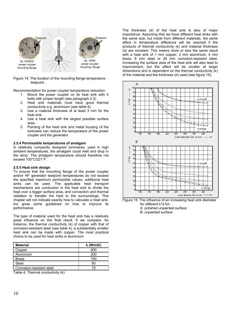
<strong>QL</strong> 55/85W<br />
power coupler<br />
mounting flange<br />
Testpoint<br />
<strong>QL</strong> 165W<br />
power coupler<br />
mounting flange<br />
Testpoint<br />
Figure 14: The location of the mounting flange temperature<br />
testpoint<br />
The thickness (d) of the heat sink is also of major<br />
importance. Assuming that we have different heat sinks with<br />
the same size, but made from different materials, the same<br />
effect in temperature difference will be reached if the<br />
products of thermal conductivity (k) and material thickness<br />
(d) are constant. This means more or less the same result<br />
with a heat sink of 1 mm copper, 2 mm aluminium, 4 mm<br />
brass, 8 mm steel or 26 mm corrosion-resistant steel.<br />
Increasing the surface area of the heat sink will also lead to<br />
improvement, but the effect will be smaller at larger<br />
dimensions and is dependent on the thermal conductivity (k)<br />
of the material and the thickness (d) used (see figure 15).<br />
Recommendation for power coupler temperature reduction:<br />
1. Mount the power coupler on its heat sink with 4<br />
bolts with proper length (see paragraph 2.3).<br />
2. Heat sink materials must have good thermal<br />
conductivity e.g. aluminium (see table 4).<br />
3. Use a material thickness of at least 3 mm for the<br />
heat sink.<br />
4. Use a heat sink with the largest possible surface<br />
area.<br />
5. Painting of the heat sink and metal housing of the<br />
luminaire can reduce the temperature of the power<br />
coupler and the generator.<br />
2.5.4 Permissible temperatures of amalgam<br />
In relatively compactly designed luminaires, used in high<br />
ambient temperatures, the amalgam could melt and drop in<br />
the lamp. The amalgam temperature should therefore not<br />
exceed 105°C/221°F.<br />
2.5.5 Heat sink design<br />
To ensure that the mounting flange of the power coupler<br />
and/or HF generator testpoint temperatures do not exceed<br />
the specified maximum permissible values, additional heat<br />
sinks can be used. The applicable heat transport<br />
mechanisms are conduction in the heat sink to divide the<br />
heat over a bigger surface area, and convection and thermal<br />
radiation to transfer the heat to the surroundings. This<br />
chapter will not indicate exactly how to calculate a heat sink,<br />
but gives some guidelines on how to improve its<br />
performance.<br />
The type of material used for the heat sink has a relatively<br />
great influence on the final result. If we compare, for<br />
instance, the thermal conductivity (k) of copper with that of<br />
corrosion-resistant steel (see table 4), a substantially smaller<br />
heat sink can be made with copper. The most practical<br />
choice to be used for heat sinks is aluminium<br />
Figure 15: The influence of an increasing heat sink diameter<br />
for different k*d for:<br />
A: polished unpainted surface<br />
B: unpainted surface<br />
Material<br />
k (W/mK)<br />
Copper 400<br />
Aluminium 200<br />
Brass 100<br />
Steel 50<br />
Corrosion-resistant steel 15<br />
Table 4: Thermal conductivity (k)<br />
10